Tunnel Magnetoresistance of a Single-Molecule Junction
Abstract
Based on the non-equilibrium Green’s function (NEGF) technique and the Landauer-Büttiker theory, the possibility of a molecular spin-electronic device, which consists of a single C60 molecule attached to two ferromagnetic electrodes with finite cross sections, is investigated. By studying the coherent spin-dependent transport through the energy levels of the molecule, it is shown that the tunnel magnetoresistance (TMR) of the molecular junction depends on the applied voltages and the number of contact points between the device electrodes and the molecule. The TMR values more than 60% are obtained by adjusting the related parameters.
I Introduction
Traditional magnetic tunnel junctions use inorganic insulators as spacers Moodera1 ; Miyazaki . However, recent experimental data have clearly shown that organic molecules can serve the same purpose and a rather large TMR can be found Tsukagoshi ; Xiong ; Dediu ; Shim ; Santos ; Ouyang ; Petta . In these experiments, spin polarized transport through molecular layers sandwiched between two magnetic layers has been demonstrated for systems involving carbon nanotubes Tsukagoshi , other organic conjugate systems Xiong ; Dediu ; Shim ; Santos , molecular bridges Ouyang , and self-assembled organic monolayers Petta . Organic materials have relatively weak spin-orbit interaction and weak hyperfine interaction, so that spin memory can be as long as a few seconds Sanvito . Such features make them ideal for spin-polarized electron injection and transport applications in molecular spintronics.
Spin-polarized transport through organic molecules sandwiched between two magnetic contacts has also been recently investigated theoretically Pati ; Senapati ; Dalgleish ; Liu ; Rocha ; Waldron ; Wang ; He ; Ning ; Wang2 ; Mehrez ; Krompiewski ; Emberly . Many of these calculations, based on density functional theory or tight-binding model, have shown that by changing the magnetic alignment of the contacts one can substantially affect the electronic current in the molecular devices. For instance, in a single benzene-1-4-dithiolate molecule sandwiched between two Ni clusters, parallel magnetic alignment led to significantly higher current (about one order of magnitude) than antiparallel alignment, suggesting the possibility of a molecular spin valve Pati .
Among many types of molecules, the fullerene C60 which is one of the most well-investigated organic semiconductors, is suitable as a molecular bridge in magnetic tunnel junctions, because its lowest unoccupied molecular orbital (LUMO) is situated at relatively lower energies in comparison with the other organic molecules. In recent years, the electrical and magnetic properties of C60-Co nanocomposites, where Co nanoparticles are dispersed in C60 molecules have been studied Zare ; Sakai ; Miwa , and the maximum TMR ratio of about 30% at low bias voltages was reported. Recently, He et al. He2 , studied the spin-polarized transport in Ni/C60/Ni junction using density functional theory and the Landauer-Büttiker formalism. They showed that the binding sites of Ni on C60 molecule play a crucial role in the transport properties of the system and a large value for junction magnetoresistance was predicted. We believe, however, that no theoretical study on spin-polarized transport through a single C60 molecule and its TMR effect, based on tight-binding method, has so far been reported.
In this paper, we use a single C60 molecule in between two ferromagnetic (FM) electrodes, instead of the usual insulator layer as in the standard TMR setup, to investigate the possibility of a single-molecule spintronics device. An interesting feature of the C60 molecule is the emergence of a quantum loop current which is related to the degeneracy of the energy levels of the molecule and its magnitude can be much larger than that of the source-drain current Naka . This feature is useful for spin-polarized transport through the molecule. Our approach indicates that the spin currents in such a molecular junction are mainly controlled by the molecular field of the FM electrodes, the electronic structure of the molecule and its coupling to the electrodes.
II Model and formalism
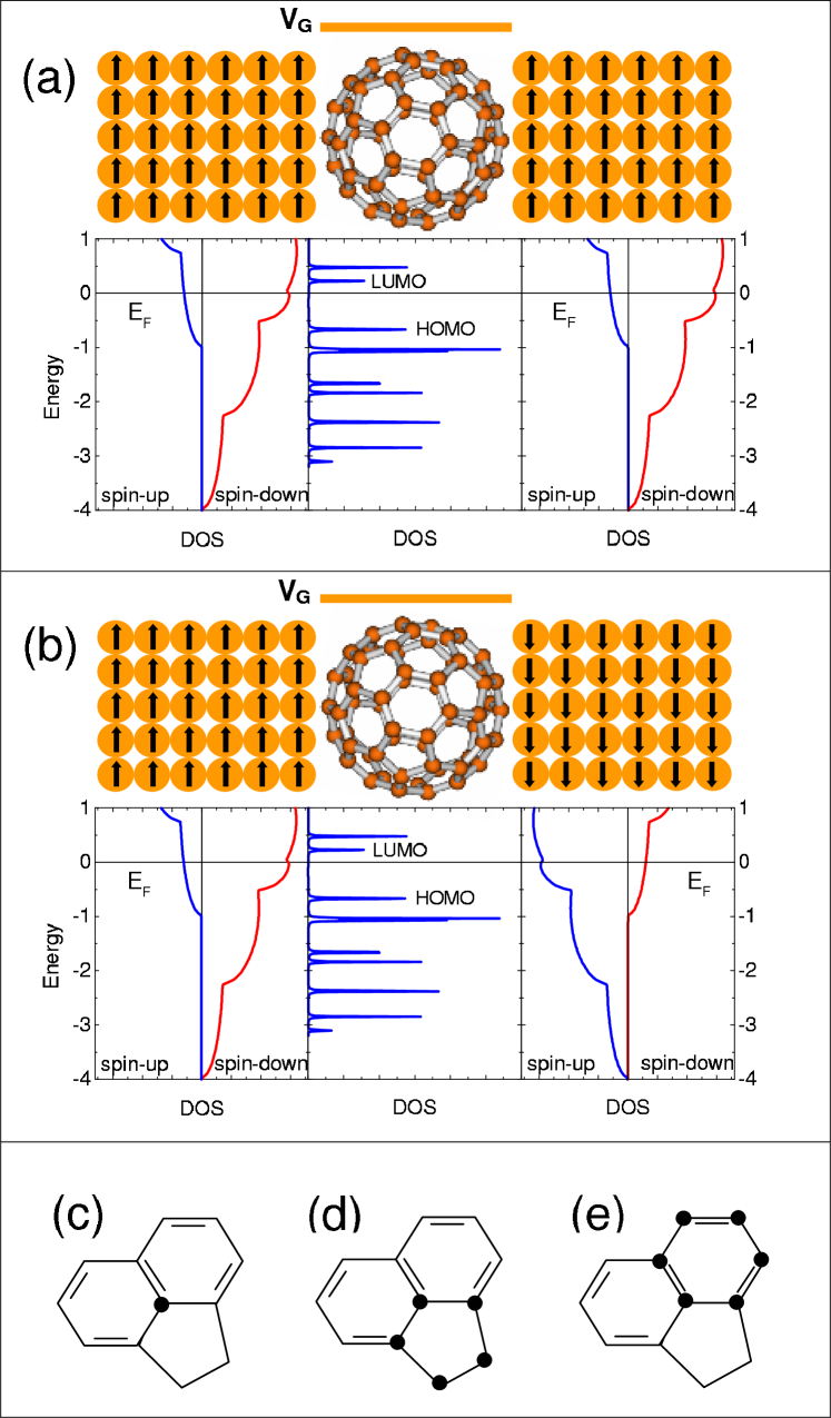
We calculate the spin currents through a single C60 molecule, sandwiched between two semi-infinite FM electrodes with simple cubic structure and square cross section (- plane). The model of such a structure is shown schematically in Fig. 1(a) and 1(b). Since the electron conduction is mainly determined by the central part of the junction, the electronic structure of this part should be resolved in detail. It is therefore reasonable to decompose the total Hamiltonian of the system as
| (1) |
The Hamiltonian of the left () and right () electrodes is described within the single-band tight-binding approximation and is written as
| (2) |
where () creates (destroys) an electron with spin at site in electrode (=, ), the hoping parameter is equal to for the nearest neighbors and zero otherwise. Here, is the spin independent on-site energy and will be set to as a shift in energy, is the internal exchange energy with denoting the molecular field at site , and being the conventional Pauli spin operator. The Hamiltonian of the C60 molecule in the absence of FM electrodes is expressed as
| (3) |
where () creates (destroys) an electron with spin at site of C60 and is the on-site energy and will be set to zero except in the presence of gate voltage that shifts the energy levels of the molecule and hence . The hoping strength in C60 molecule depends on the C-C bond length; thus, we assume different hoping matrix elements: for the single bonds and for the double bonds. Most recently, we have shown that the effect of bond dimerization may considerably affect the electron conduction through the molecule under suitable conditions Saffar1 . Finally, describes the coupling between the FM leads and the molecule and takes the form
| (4) |
The hopping elements between the lead orbitals and the orbitals of the molecule are taken to be . In this study we assume that the electrons freely propagate and the only resistance arising from the contacts. This means that the transport is ballistic Datta ; therefore, we set , because the value of should not be smaller than the order of . On the other hand, we assume that the spin direction of the electron is conserved in the tunneling process through the molecule. Therefore, there is no spin-flip scattering and the spin-dependent transport can be decoupled into two spin currents: one for spin-up and the other for spin-down. This assumption is well-justified since the spin diffusion length in organics is about 4 nm Sanvito and especially in carbon nanotubes is at least 130 nm Tsukagoshi , which are greater than the diameter of C60 molecule ( 0.7 nm).
Since the total Hamiltonian does not contain inelastic scatterings, the spin currents for a constant bias voltage, , are calculated by the Landauer-Büttiker formula based on the NEGF method Datta :
| (5) |
where is the Fermi distribution function, are the chemical potentials of the electrodes, and is the spin-, energy- and voltage-dependent transmission function. The spin-dependent Green’s function of the C60 molecule coupled to the two FM electrodes (source and drain) in the presence of the bias voltage is given as
| (6) |
where and describe the self-energy matrices which contain the information of the electronic structure of the FM electrodes and their coupling to the molecule. These can be expressed as where is the hopping matrix that couples the molecule to the leads and is determined by the geometry of the molecule-lead bond. are the surface Green’s functions of the uncoupled leads i.e., the left and right semi-infinite magnetic electrodes, and their matrix elements are given by
| (7) |
where , , ,
| (8) |
and
| (9) |
Here, () are integers, , and with is the number of lattice sites in the direction. Note that and correspond to the number of atoms at the cross-section of the FM electrodes. Using , the coupling matrices , also known as the broadening functions, can be expressed as .
In the semi-infinite FM electrodes described by the single-band tight-binding model, only the central site at the cross section is connected to the molecule. Furthermore, when the molecule is brought close to an electrode, the bonding between them will depend on the molecule orientation. This orientation can be such that only one carbon atom, a pentagon or a hexagon of the C60 molecule be in contact with the leads [see Figs. 1(c)-1(e)]. Therefore, one can expect different conduction through the molecule, which arises due to the resonant tunneling and the quantum interference effects. Our approach, as a real-space method, makes it possible to model arbitrarily the number of contacts. In this regard, the core of the problem lies in the calculation of the spin-dependent self-energies and . In the case of contact through a single carbon atom of the molecule, only one element of the self-energy matrices is non-zero. However, for the transport through opposite pentagons or hexagons, 25 or 36 elements of the self-energy matrices are non-zero, respectively.
The total charge current is given by . In this case, we calculate the TMR ratio from the usual definition: , where are the total currents in the parallel and antiparallel alignments of magnetizations in the FM electrodes, respectively.
III Results and discussion
We now use the method described above to study the coherent spin-dependent transport and magnetoresistance effect of FM/C60/FM molecular junction. We have done the numerical calculations for the case that the direction of magnetization in the left FM electrode is fixed in the + direction, while the magnetization in the right electrode is free to be flipped into either the + or - direction. We set =1.5 eV, =1 eV, , , , and =300 K in the calculations.
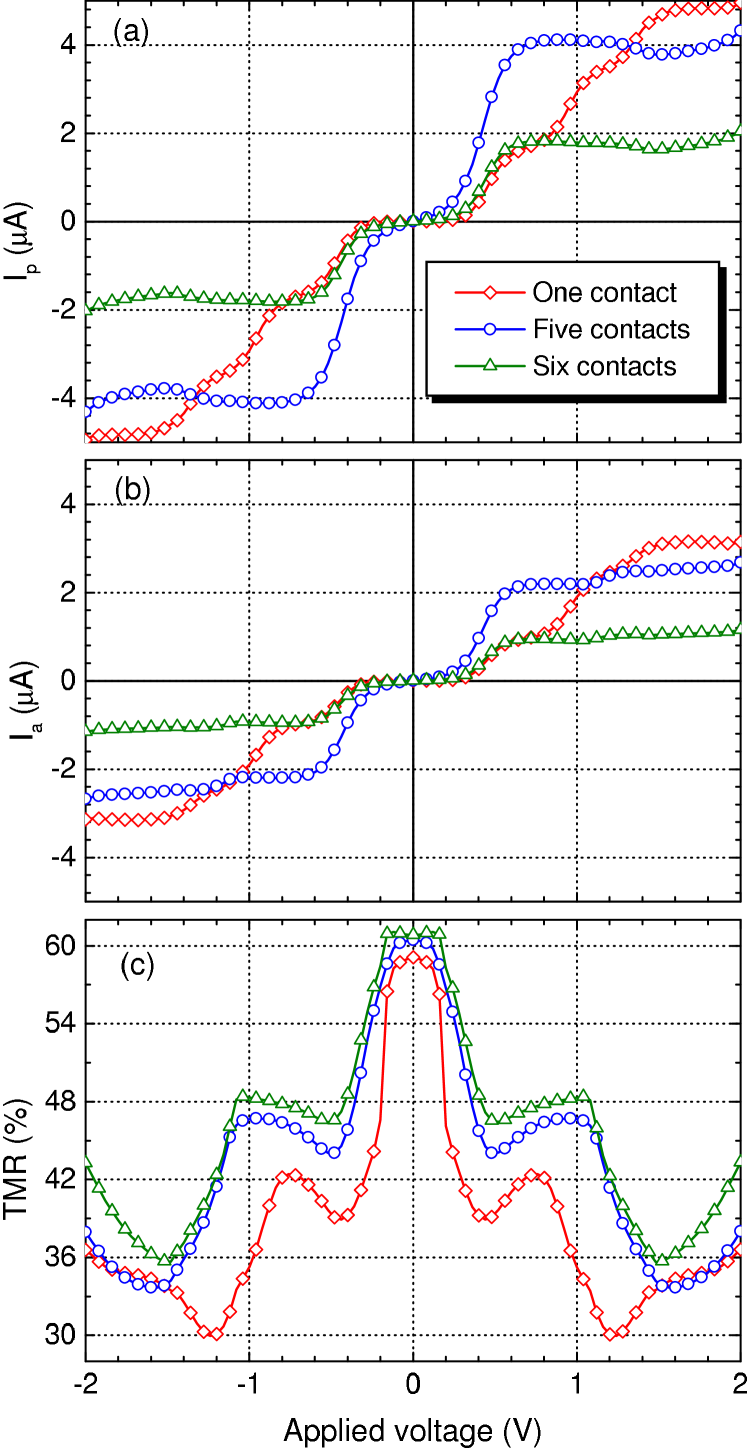
In Fig. 2 we show the current-voltage (-) characteristics (in the parallel and antiparallel alignments) and also the TMR as a function of applied voltage for three different ways of coupling between the C60 molecule and the FM electrodes. These three cases were chosen as the most probable experimental orientations Hashizume . As can be seen, the - curves show a steplike behavior which indicates that a new channel is opened. The values of currents in the parallel configuration are nearly two times larger than that in the case of antiparallel one. The difference between and is related to the asymmetry of surface density of states (SDOS) of the FM electrodes for spin-up and spin-down electrons [see Figs. 1(a) and 1(b)]Explain , and the quantum tunneling phenomenon through the molecule. Here, we have assumed that only itinerant sp-like electrons contribute to the tunneling current, which is reasonable when the distance between the two FM electrodes is greater than 0.5 nm Munzenberg .
In the parallel alignment, minority electrons go into the minority states by tunneling through the molecule and there is no asymmetry in the SDOS. If, however, the two FM electrodes are magnetized in opposite directions, the minority (majority) electrons from the left electrode seek empty majority (minority) states in the right electrode, that is, asymmetry in the SDOS. In fact, in the antiparallel alignment, the tunneling currents for both spin channels are asymmetric with respect to voltage inversion (not shown). Consequently, the parallel arrangement gives much higher total current through the C60 molecule than does the antiparallel arrangement. This difference in the total currents is the origin of TMR effect which has been shown in Fig. 2(c). The TMR ratio has it maximum value (more than 60%) at low bias voltages. With increasing the applied voltage, we first observe that the TMR decreases. Such a behavior is similar to the conventional magnetic tunnel junctions Moodera3 . With further increase in the bias voltage, the TMR ratio increases and then, the reduction and enhancement of TMR are repeated. Recently, using C60-Co nanocomposites, Miwa et al. Miwa measured a magnetoresistance value as large as 18% due to the spin-polarized tunneling of carriers between Co nanoparticles via C60 molecules. Our bias-voltage dependence of TMR is qualitatively in agreement with their results. A similar bias-dependent behavior in which TMR ratio increases with applied voltage, using a EuS spin-filter tunnel barrier in conventional junctions, has also been reported Nagahama2 .
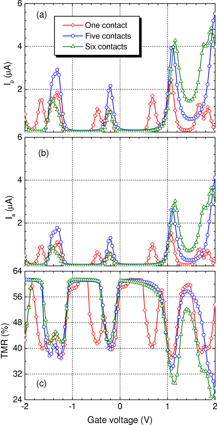
In order to investigate the other features of the junction, we show in Fig. 3 the effects of gate voltage on the total currents and the TMR in the cases of single and multiple contacts. When the gate voltage is zero, we showed in Fig. 2(c) that the maximum values for the TMR are obtained at low applied voltages ( V). In such cases, the number of states contained in the energy window between and is zero, because the energy window lies in the highest occupied molecular orbital (HOMO)-LUMO gap of the C60 molecule [Figs. 1(a) and 1(b)], where there is no molecular level. Therefore, the current flow mechanism is tunneling. For this reason, the voltage dependence of the TMR effect at low voltages is similar to that of the conventional magnetic tunnel junctions. It is worth mentioning that in the selected voltage interval, we did not observe significant changes in the transmission spectra with increasing the bias voltage.
Applying a gate voltage shifts the molecular levels relative to the Fermi level of electrodes, and hence the transmission coefficients may significantly vary Saffar1 . Since the currents depend on the molecular density of states lying between and , then, by increasing the gate voltage, HOMO or LUMO peak moves inside the energy window and the total currents and increase. In this case, for either negative or positive gate voltages, the current flow mechanism is resonant tunneling, and a peak appears in the current curves. Figures 3(a) and 3(b) show that the currents vanish in a wide range of gate voltages, because in these voltages there is no resonant level inside the energy window. In both figures, the peaks appear at the same voltages which confirm that the appearance of current peaks is due to the molecular levels. However, the height of peaks is different which is due to the difference in the spin-dependent SDOS of the FM electrodes. The results suggest that the C60 molecule is an interesting candidate for operation of devices as a nano-scale current switch. Also, with increasing the number of contact points between the device electrodes and the molecule, the interference effects around these points become important, some resonances might completely disappear, and the spin current changes. This is the reason of difference between the currents in the single and multiple contacts [see Figs. 2 and 3] Saffar1 ; Paul ; Palacios .
IV Conclusion
Using the NEGF method and the Landauer-Büttiker theory, we have investigated the possibility of making a C60-based magnetic tunnel junction. We have shown that coupling between the single C60 molecule and magnetic electrodes in FM/C60/FM structure, produces large magnetoresistance effects (greater than 60%) that can be modulated by using the molecule orientation, bias and gate voltages to control the spin-polarized transport. The present study advances the fundamental understanding of spin-dependent transport in molecular junctions and suggests that the C60 molecule is an interesting candidate for application in the magnetic memory cells and spintronic devices.
Throughout this study, we have ignored the effects of inelastic scattering and the magnetic anisotropy of the FM electrodes due to the reduced dimensionality and the geometry of the system. These factors can affect the spin-dependent transport and hence, another improved approach is needed for more accurate results.
Acknowledgement
The author thanks Professor J.S. Moodera for valuable comments. This work was supported by Payame Noor University grant.
References
- (1) J. S. Moodera, L. R. Kinder, T. M. Wong, and R. Meservey, Phys. Rev. Lett. 74, 3273 (1995).
- (2) T. Miyazaki and N. Tezuka, J. Magn. Magn. Mater. 139, L231 (1995).
- (3) K. Tsukagoshi, B. W. Alphenaar, and H. Ago, Nature 401, 572 (1999).
- (4) Z. H. Xiong, D. Wu, Z. V. Vardeny, and J. Shi Nature 427, 821 (2004).
- (5) V. Dediu et al., Solid State Commun. 122, 181 (2002).
- (6) J. H. Shim et al., Phys. Rev. Lett. 100, 226603 (2008).
- (7) T. S. Santos et al., Phys. Rev. Lett. 98, 016601 (2007).
- (8) M. Ouyang and D. D. Awschalom, Science 301, 1074 (2003).
- (9) J. R. Petta, S. K. Slater, and D. C. Ralph, Phys. Rev. Lett. 93, 136601 (2004).
- (10) S. Sanvito, Nature Nanotechnology 2, 204 (2007).
- (11) R. Pati et al., Phys. Rev. B 68, 100407(R) (2003).
- (12) L. Senapati, R. Pati and S. C. Erwin, Phys. Rev. B 76, 024438 (2007).
- (13) H. Dalgleish and G. Kirczenow, Phys. Rev. B 72, 184407 (2005); Phys. Rev. B 73, 235436 (2006).
- (14) R. Liu et al., Nano Lett. 5, 1959 (2005).
- (15) A. R. Rocha et al., Nat. Mater. 4, 335 (2005).
- (16) D. Waldron et al., Phys. Rev. Lett. 96, 166804 (2006).
- (17) B. Wang et al., Phys. Rev. B 75, 235415 (2007).
- (18) H. He et al., Phys. Rev. B 73, 195311 (2006).
- (19) Z. Ning, Y. Zhu, J. Wang, and H. Guo, Phys. Rev. Lett. 100, 056803 (2008).
- (20) R. Q. Wang, Y. Q. Zhou, B. Wang, and D. Y. Xing, Phys. Rev. B 75, 045318 (2007).
- (21) H. Mehrez et al., Phys. Rev. Lett. 84, 2682 (2000).
- (22) S. Krompiewski et al., Phys. Rev. B 69, 155423 (2004).
- (23) E. G. Emberly and G. Kirczenow, Chem. Phys. 281, 311 (2002).
- (24) H. Zare-Kolsaraki and H. Micklitz, Eur. Phys. J. B 40, 103 (2004).
- (25) S. Sakai et al., Appl. Phys. Lett. 89, 113118 (2006).
- (26) S. Miwa et al., Phys. Rev. B 76, 214414 (2007).
- (27) H. He, R. Pandey, and S. P. Karna, Chem. Phys. Lett. 439, 110 (2007).
- (28) S. Nakanishi and M. Tsukada, Phys. Rev. Lett. 87, 126801 (2001).
- (29) A. Saffarzadeh, J. Appl. Phys. 103, 083705 (2008).
- (30) S. Datta, Electronic Transport in Mesocopic System (Cambridge University Press, Cambridge, 1997).
- (31) T. Hashizume et al., Phys. Rev. Lett. 71, 2959 (1993).
- (32) We have calculated the spin-up and spin-down SDOS of the electrodes, within the single-band tight-binding approximation, by at the central site of the cross-section. These densities are analogous to the SDOS of a semi-infinite magnetic simple cubic lattice. A. Saffarzadeh, Surf. Sci. 600, 4785 (2006).
- (33) M. Münzenberg and J. S. Moodera, Phys. Rev. B 70, 060402(R) (2004).
- (34) J. S. Moodera et al., Phys. Rev. Lett. 80, 2941 (1998).
- (35) T. Nagahama et al., Phys. Rev. Lett. 99, 016602 (2007).
- (36) M. Paulsson and S. Stafström, J. Phys.: Condens. Matter 11, 3555 (1999).
- (37) J. J. Palacios et al., Nanotechnology 12, 160 (2001).