Epitaxial growth and magnetic properties of Sr2CrReO6 thin films
Abstract
The double perovskite Sr2CrReO6 is an interesting material for spintronics, showing ferrimagnetism up to 635 K with a predicted high spin polarization of . We fabricated Sr2CrReO6 epitaxial films by pulsed laser deposition on (001)-oriented SrTiO3 substrates. Phase-pure films with optimum crystallographic and magnetic properties were obtained by growing at a substrate temperature of C in pure O2 of mbar. The films are -axis oriented, coherently strained, and show less than 20% anti-site defects. The magnetization curves reveal high saturation magnetization of 0.8 per formula unit and high coercivity of 1.1 T, as well as a strong magnetic anisotropy.
pacs:
75.70.-i 81.15.Fg, 85.75.-dI Introduction
The ferrimagnetic double perovskites O6, with a magnetic and a non-magnetic transition metal ion Kobayashi et al. (1998); Serrate et al. (2007); Philipp et al. (2003a), are attractive magnetic materials. Of particular interest is Sr2CrReO6 (SCRO) Kato et al. (2002); Asano et al. (2005), as it exhibits a ferrimagnetic transition temperature of K well above room temperature, in combination with a quasi half-metallic band structure according to theoretical calculations Vaitheeswaran et al. (2005). This high is strongly correlated to a large induced magnetic spin moment at the non-magnetic Re site Majewski et al. (2005a, b). can be further increased by electron doping, as demonstrated e.g. in Sr2FeMoO6, Sr2CrWO6, or Sr2CrOsO6 by band filling Navarro et al. (2001); Geprägs et al. (2006); Krockenberger et al. (2007). The strong, long-range magnetic interaction is attributed to a kinetic energy driven exchange process, in which the hybridization between itinerant electrons on the sites and the localized moments on the sites leads to an induced magnetic moment of the non-magnetic ions Sarma et al. (2000); Fang et al. (2001). Regarding device applications, the strong influence of the growth conditions on the structural, magnetic, and electronic properties of double perovskites is demanding. In particular, it became evident that a key parameter to understand the properties of double perovskites is the amount of anti-site defects ( ions on sites and vice versa). It was shown that the saturation magnetization decreases with increasing amount of anti-site defects Balcells et al. (2001). Therefore, a thorough understanding of the growth process is a key prerequisite for obtaining thin films with optimum physical properties. While the growth of Sr2FeMoO6 and Sr2CrWO6 thin films has been investigated in detailWesterburg et al. (2000); Philipp et al. (2001); Philipp et al. (2003b); Shinde et al. (2003), little is known about Sr2CrReO6 so far Asano et al. (2004, 2005, 2007).
Here, we report on the epitaxial growth of -axis oriented SCRO thin films on (001) SrTiO3 (STO) substrates, and discuss the effects of growth temperature, growth atmosphere, and pressure on the film quality. We identify optimal growth parameters leading to SCRO films with excellent crystalline quality as well as magnetic properties comparable to bulk SCRO.
II Growth and crystallographic characterization
We have used pulsed laser deposition (PLD) Klein et al. (1999) to grow the SCRO films from a stoichiometric target, which was fabricated using an oxygen getter control technique to ensure stoichiometry Yamamoto et al. (2000). To identify the optimal growth conditions, we have deposited films (i) in three different atmospheres: O2, Ar, and a mixture of Ar/O2 (99/1 by volume), (ii) at different pressures, and (iii) at different substrate temperatures . The structural and magnetic properties of the SCRO thin films were analyzed using in-situ reflection high energy electron diffraction (RHEED), high resolution x-ray diffraction (HRXRD), SQUID magnetometry, and high resolution transmission electron microscopy (HRTEM). The film thickness was determined by x-ray reflectometry.
Comparing samples grown in O2, Ar, and Ar/O2, we find that high-quality, phase-pure SCRO films are obtained only in a growth atmosphere containing oxygen. In particular, the presence of oxygen during the growth seems to be essential to achieve Cr/Re sub-lattice ordering Venimadhav et al. (2006). In the following, we therefore focus on films grown in pure O2 atmosphere of mbar. Higher pressure was found to lead to parasitic phases, lower pressure to a reduced saturation magnetization. Another important deposition parameter is the laser fluence on the target, determining the energy of the ablated particles. We found no significant change of the magnetic and crystalline quality upon varying from to . Moreover, the laser pulse repetition rate also had no noticeable effect on the anti-site disorder in our SCRO films, in contrast to what was found for Sr2FeMoO6 films Sanchez et al. (2004). We therefore used a and Hz in all subsequent growth runs.
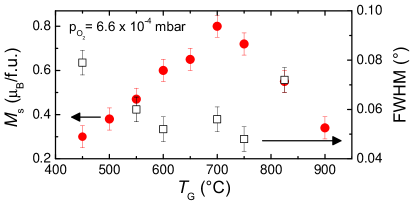
The influence of the substrate temperature on the structural and magnetic properties of SCRO thin films is summarized in Fig. 1. It is evident that the full width at half maximum (FWHM) of the rocking curve of the SCRO (004) reflection stays almost constant on a low value of about for . Only at the lowest and highest , the FWHM increases up to . This indicates that SCRO thin films can be grown with low mosaic spread in a large temperature window from C to C. We note that the mosaic spread of the SCRO thin films is close to that of the STO substrate (typically ). In contrast, the saturation magnetization peaks around C. As a strong correlation between and the sub-lattice order is often observed in ferrimagnetic double perovskites Balcells et al. (2001), Fig. 1 suggests that SCRO films grown at C show a high degree of sub-lattice order and thus a small fraction of anti-site defects. That is, SCRO thin films with optimal structural and magnetic properties are obtained for C in a pure O2 atmosphere of mbar.
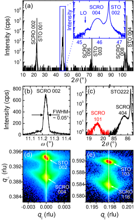
Fig. 2 shows the structural properties achieved for epitaxial SCRO films which were deposited at the optimum growth parameters described above. The - scan reveals no crystalline parasitic phases. As shown in the inset, the observation of Laue oscillations provides evidence for a coherent film growth. Furthermore, the small FWHM of the rocking curve of the SCRO (002) reflection of only demonstrates high crystalline quality with low mosaic spread. The Cr/Re sub-lattice order of our SCRO films can be inferred from the intensity of the superstructure (101) reflection shown in Fig. 2(c). This superstructure peak has finite intensity only for a finite amount of ordering on the Cr/Re sub-lattice. The amount of anti-site defects can be determined from the measured intensity ratio of the (101) and (404) reflections. Comparing the measured intensity to simulations, performed using the software package TOPAS from Bruker company, the amount of anti-site defects is estimated to less than 20%. More detailed information about the mosaicity and the strain state can be obtained from the reciprocal space maps around the (004) and (116) reflections shown in Figs. 2(d) and (e). Clearly no -shift of the symmetric (004) and asymmetric (116) SCRO film reflections with respect to the corresponding STO substrate reflections is observed. This demonstrates pseudomorphic growth up to the maximum film thickness of 65 nm. The reciprocal space maps and the in-plane cube-on-cube growth derived from an in-plane -scan (not shown) reveal a tetragonal symmetry of the SCRO thin films, with lattice parameters of and . Comparing the measured in-plane lattice constant to the value of bulk SCRO Serrate et al. (2007) shows that the tensile epitaxial coherency strain of the SCRO films grown on STO substrates is negligibly small and the films can be regarded as strain-free.
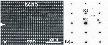
The quality of the interface between the STO substrate and the SCRO film was investigated by HRTEM. The bright-field HRTEM micrograph along the -direction of the STO substrate shown in Fig. 3(a) demonstrates the perfect epitaxial growth of SCRO on STO. Neither dislocations nor structural defects could be detected. To obtain information on the Cr/Re sub-lattice ordering, electron diffraction was performed, as shown in Fig. 3(b). After foil thickness determination from the intensity ratio , the anti-site defects of the Cr/Re sub-lattice can be estimated to be less than 17%, e.g. from the intensity ratio . Note that the (011) peak is a superstructure peak with vanishing intensity for complete disorder on the Cr/Re sub-lattice. This provides additional evidence for a highly ordered Cr/Re sub-lattice in our SCRO films.
III Magnetic properties
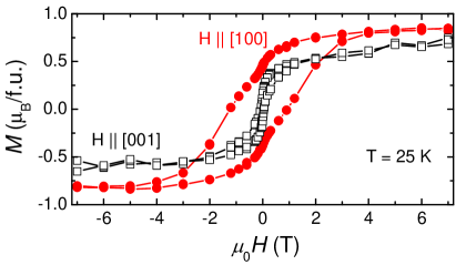
We finally address the magnetic properties of the SCRO films. Fig. 4 exemplarily shows the curves of a 31 nm thick SCRO film recorded at 25 K. For the external magnetic field applied in-plane along , the measured saturation magnetization is in good agreement with of our polycrystalline target material and the literature values ranging between 0.8 and at low temperature Kato et al. (2002); Asano et al. (2004). Recent model calculations including spin-orbit coupling Vaitheeswaran et al. (2005) predicted /f.u. for perfect sub-lattice order. Assuming that decreases about linearly with increasing sub-lattice disorder, the measured amount of anti-site defects of less than 20% translates into an expected saturation magnetization larger than /f.u., again in good agreement with the measured value. The measured curves also reveal a very large coercive field . This value again agrees well with literature data ranging from 1 to 1.5 T at 4.2 K Kato et al. (2002); Asano et al. (2004), demonstrating that the SCRO compound is a hard ferromagnet. However, in contrast to a previous study Asano et al. (2004) we observe a strong magnetic anisotropy in our SCRO films. This is evident from the hysteresis loop with oriented perpendicular to the film plane. For this field orientation, the magnetization loop is rectangular-shaped, with a much lower coercive field . Furthermore, the field at which the hysteresis loop closes is also reduced to about 0.7 T, as compared to more than 3 T for the magnetic field applied in the film plane. We note that the apparent dependence of on the field orientation can be attributed to the large saturation field of SCRO, making the unambiguous determination of the diamagnetic contribution of the substrate difficult. Additionally, the large spin-orbit coupling in SCRO is expected to result in strong magnetic anisotropy.
IV Conclusions
In conclusion, we have identified the optimal parameters for the epitaxial growth of -axis oriented SCRO films on (001) STO by pulsed laser deposition. The films have excellent crystalline quality with a high degree of Cr/Re sub-lattice order. The FWHM of the rocking curves is as small as , reaches /f.u., and the coercivity is 1.1 T. These parameters make SCRO thin films an outstanding ferrimagnetic double perovskite for spintronic applications.
Financial support by the DFG via the priority programs 1157 and 1285 (project nos. GR 1132/13 and 1132/14), GO 944/3-1, and the Excellence Cluster ”Nanosystems Initiative Munich (NIM)” are gratefully acknowledged.
References
- Kobayashi et al. (1998) K.-I. Kobayashi, T. Kimura, H. Sawada, K. Terakura, and Y. Tokura, Nature 395, 677 (1998).
- Serrate et al. (2007) D. Serrate, J. D. Teresa, and M. Ibarra, J. Phys.: Cond. Matt. 19, 023201 (2007).
- Philipp et al. (2003a) J. B. Philipp, P. Majewski, L. Alff, A. Erb, R. Gross, T. Graf, M. S. Brandt, J. Simon, T. Walther, W. Mader, D. Topwal, and D. D. Sarma, Phys. Rev. B 68, 144431 (2003a).
- Kato et al. (2002) H. Kato, T. Okuda, Y. Okimoto, Y. Tomioka, Y. Takenoya, A. Ohkubo, M. Kawasaki, and Y. Tokura, Appl. Phys. Lett. 81, 328 (2002).
- Asano et al. (2005) H. Asano, N. Koduka, K. Imaeda, M. Sugiyama, and M. Matsui, IEEE Trans. Magn. 41, 2811 (2005).
- Vaitheeswaran et al. (2005) G. Vaitheeswaran, V. Kanchana, and A. Delin, Appl. Phys. Lett. 86, 032513 (2005).
- Majewski et al. (2005a) P. Majewski, S. Geprägs, A. Boger, M. Opel, A. Erb, R. Gross, G. Vaitheeswaran, V. Kanchana, A. Delin, F. Wilhelm, A. Rogalev, and L. Alff, Phys. Rev. B 72, 132402 (2005a).
- Majewski et al. (2005b) P. Majewski, S. Geprägs, O. Sanganas, M. Opel, R. Gross, F. Wilhelm, A. Rogalev, and L. Alff, Appl. Phys. Lett. 87, 202503 (2005b).
- Navarro et al. (2001) J. Navarro, C. Frontera, L. Balcells, B. Martinez, and J. Fontcuberta, Phys. Rev. B 64, 092411 (2001).
- Geprägs et al. (2006) S. Geprägs, P. Majewski, R. Gross, C. Ritter, and L. Alff J. Appl. Phys. 99, 08J102 (2006b).
- Krockenberger et al. (2007) Y. Krockenberger, K. Mogare, M. Reehuis, M. Tovar, M. Jansen, G. Vaitheeswaran, V. Kanchana, F. Bultmark, A. Delin, F. Wilhelm, A. Rogalev, A. Winkler, and L. Alff, Phys. Rev. B 75, 020404 (2007).
- Sarma et al. (2000) D. D. Sarma, P. Mahadevan, T. Saha-Dasgupta, S. Ray, and A. Kumar, Phys. Rev. Lett. 85, 2549 (2000).
- Fang et al. (2001) Z. Fang, K. Terakura, and J. Kanamori, Phys. Rev. B 63, 180407 (2001).
- Balcells et al. (2001) L. Balcells, J. Navarro, M. Bibes, A. Roig, B. Martinez, and J. Fontcuberta, Appl. Phys. Lett. 78, 781 (2001).
- Westerburg et al. (2000) W. Westerburg, D. Reisinger, and G. Jakob, Phys. Rev. B 62, R767 (2000).
- Philipp et al. (2001) J. B. Philipp, D. Reisinger, M. Schonecke, A. Marx, A. Erb, L. Alff, R. Gross, and J. Klein, Appl. Phys. Lett. 79, 3654 (2001).
- Philipp et al. (2003b) J. B. Philipp, D. Reisinger, M. Schonecke, M. Opel, A. Marx, A. Erb, L. Alff, and R. Gross, J. Appl. Phys. 93, 6853 (2003b).
- Shinde et al. (2003) S. R. Shinde, S. B. Ogale, R. L. Greene, T. Venkatesan, K. Tsoi, S.-W. Cheong, and A. J. Millis, J. Appl. Phys. 93, 1605 (2003).
- Asano et al. (2004) H. Asano, N. Kozuka, A. Tsuzuki, and M. Matsui, Appl. Phys. Lett. 85, 263 (2004).
- Asano et al. (2007) H. Asano, N. Koduka, Y. Takahashi, and M. Matsui, J. Magn. Magn. Mat. 310, 2174 (2007).
- Klein et al. (1999) J. Klein, C. Höfener, L. Alff, and R. Gross, Superc. Sci. Techn. 12, 1023 (1999).
- Yamamoto et al. (2000) T. Yamamoto, J. Liimatainen, J. Lindén, M. Karppinen, and H. Yamauchi, J. Mat. Chem. 10, 2342 (2000).
- Venimadhav et al. (2006) A. Venimadhav, F. Sher, J. P. Attfield, and M. G. Blamire, Sol. State Comm. 138, 314 (2006).
- Sanchez et al. (2004) D. Sanchez, M. Garcia-Hernandez, N. Auth, and G. Jakob, J. Appl. Phys. 96, 2736 (2004).