Spin torque from tunneling through impurities in a magnetic tunnel junction
Abstract
We calculate the contribution to the spin transfer torque from sequential tunneling through impurities in a magnetic tunnel junction. For a junction with weakly polarized ferromagnetic contacts, the torque is found to be in the plane spanned by the magnetizations of the ferromagnetic contacts and proportional to , where is the angle between the magnetic moments. If the polarization is larger, the torque acquires a significant out-of-plane component and a different dependence on .
pacs:
85.75.-d, 72.25.-b, 73.23.HkI Introduction
A magnetic tunnel junction consists of two ferromagnetic layers, separated by an insulator. Zhang and Butler (2003); Tsymbal et al. (2003a) Magnetic tunnel junctions play a prominent role in proposals for magnetic memory applications, where the information is stored in the relative orientation of the magnetizations of the two ferromagnetic layers. The two essential operations for the realization of a memory element, reading and writing, rely on the tunneling magnetoresistance effect (the observation that the resistance of the junction depends on the relative orientation of the two ferromagnets Julliere (1975)) and the spin transfer torque (the fact that passing a large current through a magnetic tunnel junction exerts a torque on the magnetizations of the two layers. Slonczewski (1996); Berger (1996)) Although both effects also exist in metallic magnetic junctions, tunneling junctions have a significantly higher magnetoresistance and an impedance that is better matched to the requirements of semiconductor technology. Parkin et al. (1999)
Although the tunneling magnetoresistance effect has been studied experimentally and theoretically for more than 30 years, the spin transfer effect in magnetic tunnel junctions had not received attention until recently. The spin transfer torque consists of two contributions, a component in the plane spanned by the magnetization directions of the two ferromagnetic layers in the junction, and a component transverse to that plane. The out-of-plane component is also referred to as the “field-like” torque or the “nonequilibrium exchange interaction”. The in-plane torque component can be understood in terms of the non-conservation of spin for electrons tunneling between the ferromagnetic layers. Slonczewski (2005) The out-of-plane torque component has been attributed to a more subtle interference between electrons reflected off the front and back ends of the insulating barrier. Xiao et al. (2008); Manchon et al. (2008) Theoretical predictions exist for both torque contributions, with similar conclusions based on tight-binding calculations that include the full band structure of the junction Heiliger and Stiles (2008); Theodonis et al. (2006); Kalitsov et al. (2006) and free electron models that neglect most band structure effects. Xiao et al. (2008); Manchon et al. (2007, 2008) On the experimental side, quantitative measurements of both components of the spin transfer torque in tunnel junctions are possible using spin-transfer-driven ferromagnetic resonance. Tulapurkar et al. (2005); Sankey et al. (2008)
Whereas most of the theoretical approaches to the spin-transfer torque in magnetic tunnel junctions address ideal junctions, impurities and defects are known to be abundant in the MgO magnetic tunnel junctions used in experiments. Mather et al. (2006); Cha et al. (2007); Miao et al. (2008) While impurities inside the barrier are known, both theoretically Tsymbal et al. (2003b); Velev et al. (2007) and experimentally, Jansen and Moodera (1999); Miao et al. (2008) to strongly affect tunneling magnetoresistance, there has been less attention to their effect on the spin transfer torque. Manchon et al. (2007); Zhuravlev et al. (2005)
Unlike for a theory of spin torque and magnetoconductance in ideal junctions, where both phenomena are attributed to electron states that are extended on both sides of the junction, impurity-mediated transport involves localized states inside the barrier. Inside the barrier, electron-electron interactions are poorly screened, and interactions cannot simply be accounted for on the mean-field level. In this letter, we describe the impurity-mediated transport using a model of sequential tunneling that is able to incorporate interaction effects exactly. The sequential tunneling picture is valid for high temperatures or voltages (temperature and/or voltage larger than the width of the impurity state), which makes our theory applicable to all but the thinnest junctions. This puts our theory in an entirely different parameter range than Refs. Zhuravlev et al., 2005 and Manchon et al., 2007, which addressed zero temperature torques in the absence of interactions.
The concept of sequential tunneling has been used previously to describe spin-dependent transport through metal nanoparticles (or “quantum dots”) tunnel coupled to ferromagnetic electrodes. Waintal and Brouwer (2003); Cottet et al. (2004); König and Martinek (2003); Braun et al. (2004) For these systems, one considers how a current between the ferromagnetic contacts affects the spin accumulated on the nanoparticle. In the present context, we are interested in the opposite effect, the back-action of the current on the polarization of the ferromagnetic contacts. Below, we first analyze the current and torques and on the two ferromagnets in the tunnel junction for sequential tunneling through a single impurity with a single (spin degenerate) energy level, following ideas laid out in the theory of spin-dependent transport through quantum dots. We then turn to the case of magnetic tunnel junctions, where impurity-mediated contributions to the current and torque have to be summed over many impurities in the junction.
II Sequential tunneling through a single impurity
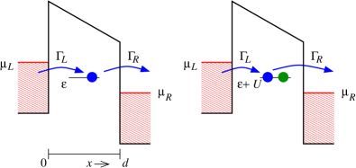
We denote the energy of the singly-occupied and doubly-occupied impurity level by and , respectively, where the interaction energy accounts for the Coulomb repulsion of the two electrons in a doubly-occupied impurity site. The left (L) and right (R) ferromagnets are held at chemical potential and , respectively. For definiteness, we assume that the bias . (See Fig. 1 for a schematic picture.) The direction of the magnetization of each ferromagnetic contact is denoted by the unit vector , . Tunneling between the impurity level and the reservoirs is described by tunneling rates and , where for the majority and minority spin directions, respectively.
The theory of sequential tunneling is applicable if the temperature is much larger than the tunneling rates . In this regime, interference effects (such as those responsible for an impurity-mediated zero-bias torque Zhuravlev et al. (2005)) are smeared out and impurity-mediated transport can be described using the probabilities that the impurity level is occupied by electrons, , and the expectation value of the impurity spin. Braun et al. (2004) Their time derivatives and are expressed in terms of particle and spin currents onto the impurity site,
| (1) |
where and are the currents from contact for processes in which the occupation changes from to and from to , respectively, and is the spin current onto the impurity site, . The component of perpendicular to causes a torque Slonczewski (1996),
| (2) |
The torques are decomposed into an in-plane component , , and an out-of-plane component ,
| (3) | |||||
| (4) |
where is the unit vector perpendicular to and ,
| (5) |
Following Ref. Braun et al., 2004, the currents , , and are expressed in terms of the tunneling rates and the distribution functions of the two reservoirs,
Here , and
| (6) | |||||
is an effective exchange field arising from virtual tunneling from the impurity level to the reservoirs. König and Martinek (2003) The exchange field is an interaction effect: in the absence of Coulomb repulsion on the impurity site.
Sequential tunneling takes place if at least one of the energies and lies between and , see Fig. 1. Since typical interaction energies are large (up to several ), we assume that . In this regime, the occupation of the impurity site can change by at most one electron. Depending on whether or lies between the chemical potentials of the source and drain contacts, the occupation of the impurity site fluctuations between and (“case I”) or and (“case II”). In case I, the only nonzero charge currents are and , whereas in case II, the nonzero charge currents are and . Below, we give the relevant expressions for case I only. Case II follows from the expressions below by making the substitutions and .
Solving Eqs. (1)–(II) for , we then calculate the current through the impurity, as well as the torques and . We then find
| (7) | |||||
| (8) | |||||
| (9) | |||||
| (10) |
with
| (11) | |||||
It is important to point out that the in-plane torque components and on the magnetizations of the source and drain contacts are, in general, not equal. (The out-of-plane components are equal because of conservation of angular momentum.) The origin of this effect is the Coulomb interaction on the impurity site, which lifts the symmetry between source and drain reservoirs. To see this, recall that in case I (for which the above equations are derived), the Coulomb interacation forbids double occupancy of the impurity site. Since the electron spin is not changed when an electron tunnels onto an empty impurity level, the electron spin may be changed only when the electron tunnels off the impurity site, or because of the action of the exchange fields and . This explains why is nonzero to lowest order in the exchange fields, whereas and are of higher order in and , respectively.
III Impurity-mediated tunneling in a magnetic tunnel junction
In a magnetic tunnel junction there will be many impurities, distributed spatially throughout the insulating spacer layer, and with a distribution of energy levels . (The energy depends on the electrostatic environment of the impurity, hence its fluctuations.) In order to add the contributions from all impurities, we characterize the impurity configuration by the density of impurities per volume and per energy, where is the distance from the source reservoir, being the width of the insulating spacer layer (see Fig. 1). We neglect fluctuations of the interaction energy , which is less susceptible to the electrostatic environment of the impurities than .
We assume that the density of impurities is small enough,
| (12) |
where is the typical width of an impurity energy level, so that the transport of an electron will take place through a single impurity only, i.e., multiple-impurity processes are ignored. The total current and torque are then written as integrals over the energy of impurities in the junction,
| (13) |
where , and , represent contributions from impurities at energy (case I) and (case II), respectively.
For barriers with rough interfaces the transverse momentum is not be conserved at the ferromagnet-insulator interface. In that case, the tunneling rates can be estimated as Slonczewski (2005)
| (14) |
where is a polarization factor and the wavefunction decay length in the spacer layer. foot We will take the junction to be symmetric, , and define . For barrier width the current and torque are dominated by impurities near the center of the barrier, . Manchon et al. (2007) The contribution of these impurities to the current and torque scales if , whereas there is a faster exponential suppression for direct tunneling or for impurities located off-center.
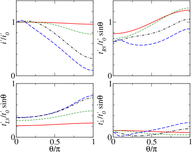
We have calculated the two contributions to the current and torque for arbitrary angle and polarization . The results are rather lengthy, and we refer to Fig. 2 for a numerical evaluation for a few representative values of . Closed form expressions could be obtained in the limit of weakly polarized ferromagnets, only. For impurities with (case I), we find
| (15) |
where
| (16) |
and . In Eq. (15) we kept only those sub-leading terms in the small- expansion that have a different dependence than the leading terms. The case II contributions are obtained by interchanging and and replacing by . The total torque is found by adding contributions for cases I and II and integrating over .
There is a striking asymmetry between the impurity-mediated in-plane torques on the source and drain reservoirs. For small polarization () and case I, the in-plane torque dominates over the other two torque terms. This is markedly different from the torque from direct tunneling, which has equal magnitudes for and . Slonczewski (2005) The situation is reversed for case II. However, as there is no a priori reason why the spectral impurity densities at energies and , which set the sizes of the torques for cases I and II, are equal, one still expects the magnitudes and to be rather different after torques from the two cases are added.
It is important to point out that both the source-drain asymmetry and the existence of an out-of-plane component of the torque are interaction effects. The source-drain asymmetry was already discussed at the end of Sec. II. That the out-of-plane torque is an interaction effect can be seen explicitly from Eq. (10), which is proportional to ( for case II). Without interactions, . (Note that the out-of-plane torque in theories without electron-electron interactions has an altogether different origin: It is caused by interference effects.Manchon et al. (2007, 2008); Xiao et al. (2008) For the temperature range we consider, , interference effects are smeared out for impurity-mediated transport.)
For strongly polarized ferromagnetic contacts () all three torque terms are of comparable magnitude, although and remain different. The order of magnitude of the torque, normalized to the impurity-mediated current , is the same as for the case of direct tunneling, normalized to the direct tunneling current Slonczewski (2005). Whereas the angular dependence of all three torque terms is the standard geometric dependence characteristic of the direct tunneling torque Slonczewski (2005); Theodonis et al. (2006); Kalitsov et al. (2006); Xiao et al. (2008); Manchon et al. (2008) if , the dependence is more complicated for strongly polarized contacts because of the presence of the exchange fields and , see Fig. 2.
IV Discussion
The impurity-mediated torque considered here coexists with the torque from direct tunneling. How can the two contributions to the torque be separated experimentally? The calculation of the previous sections shows that there are four significant differences between the impurity-mediated torque and the direct-tunneling torque: (i) The impurity-mediated torque is not symmetric under reversal of the bias, whereas the torque from direct tunneling is symmetric under bias reversal. The same holds for the impurity-mediated and direct-tunneling currents. Hence, the presence of a bias asymmetry for the current or torque is an indicator for the order-of-magnitude of the impurity-mediated contribution. (ii) The impurity-mediated torque has a nontrivial angular dependence for strongly polarized contacts, whereas the direct-tunneling torque has a sinusoidal angular dependence. The angular dependence of the torque is observable in current-induced ferromagnetic resonance experiments.Tulapurkar et al. (2005); Sankey et al. (2008) (iii) Impurity-mediated and direct-tunneling contributions to the current and torque have different dependences on the thickness of the insulating layer: The impurity-mediated contribution scales , whereas the direct-tunneling contribution scales . This means that the impurity-mediated torque will dominate for sufficiently thick junctions, irrespective of the impurity concentration. (iv) The bias-dependence of the impurity-mediated torque tracks the spectral impurity density , whereas the bias-dependence of the direct-tunneling torque should be less pronounced. (The spectral impurity density is not the only source of a bias dependence: One also expects a bias dependence from the bias-dependence of the tunneling rates . However, that bias dependence is likely to be the shared between the two contributions to the torque.) For the impurity-mediated torque, resonant features in the spectral density, which can be brought out using more detailed theoretical modeling Tsymbal et al. (2003b); Velev et al. (2007); Zhuravlev et al. (2005) or additional experiments,Miao et al. (2008); Jansen and Moodera (1999) can then be correlated with the bias dependence of the torque.
It is instructive to give a rough comparison of the magnitudes of the impurity-mediated and direct tunneling currents or torques. Since they have different exponential dependences on the barrier thickness , we estimate the pre-exponential factors by order of magnitude only and neglect differences between the three relevant microscopic length scales (Fermi wavelengths for majority and minority electrons in the ferromagnetic contacts, wavefunction decay length ). Dimensional analysis then estimates the ratio of impurity-mediated and direct currents , and torques , as
| (17) |
where is the impurity concentration. Reference Zhuravlev et al., 2005 uses m-3, whereas an estimate using the barrier height in MgO and the effective mass of the electron givesFaure-Vincent et. al. (2002) m. From this, we conclude that impurity-mediated transport dominates already for barrier thickness m, well within the experimentally relevant range. A more accurate comparison requires knowledge about the spectral density specific to the impurity type and is beyond the scope of this article.
Acknowledgements.
We acknowledge helpful discussions with Bob Buhrman, Dan Ralph, John Read, Joern Kupferschmidt and Lin Xue. This work was supported by the Cornell Center for Nanoscale Systems under NSF Grant No. EEC-0117770 and by the NSF under Grant No. DMR 0705476.References
- Zhang and Butler (2003) X.-G. Zhang and W. H. Butler, J. Phys.: Condens. Matter 15, R1603 (2003).
- Tsymbal et al. (2003a) E. Y. Tsymbal, O. N. Mryasov, and P. R. LeClair, J. Phys.: Condens. Matter 15, R109 (2003a).
- Julliere (1975) M. Julliere, Phys. Lett. A 54, 225 (1975).
- Slonczewski (1996) J. C. Slonczewski, J. Magn. Magn. Mater. 159, 1 (1996).
- Berger (1996) L. Berger, Phys. Rev. B 54, 9353 (1996).
- Parkin et al. (1999) S. S. P. Parkin, K. P. Roche, M. G. Samant et al., P. M. Rice, R. B. Beyers, R. E. Scheuerlein, E. J. O’Sullivan, S. L. Brown, J. Bucchigano, D. W. Abraham, et al., J. Appl. Phys. 85, 5828 (1999).
- Slonczewski (2005) J. C. Slonczewski, Phys. Rev. B 71, 024411 (2005).
- Xiao et al. (2008) J. Xiao, G. E. W. Bauer, and A. Brataas, Phys. Rev. B 77, 224419 (2008).
- Manchon et al. (2008) A. Manchon, N. Ryzhanova, A. Vedyayev, M. Chschiev, and B. Dieny, J. Phys.: Condens. Matter 20, 145208 (2008).
- Heiliger and Stiles (2008) C. Heiliger and M. D. Stiles, Phys. Rev. Lett. 100, 186805 (2008).
- Theodonis et al. (2006) I. Theodonis, N. Kioussis, A. Kalitsov, M. Chshiev, and W. H. Butler, Phys. Rev. Lett. 97, 237205 (2006).
- Kalitsov et al. (2006) A. Kalitsov, I. Theodonis, N. Kioussis, M. Chshiev, W. H. Butler, and A. Vedyayev, J. Appl. Phys. 99, 08G501 (2006).
- Manchon et al. (2007) A. Manchon, N. Ryzhanova, N. Strelkov, A. Vedyayev, and B. Dieny, J. of Phys.: Condens. Matter 19, 165212 (2007).
- Tulapurkar et al. (2005) A. A. Tulapurkar, Y. Suzuki, A. Fukushima, H. Kubota, H. Maehara, K. Tsunekawa, D. D. Djayaprawira, N. Watanabe, and S. Yuasa, Nature 438, 339 (2005); H. Kubota, A. Fukushima, K. Yakushiji, T. Nagahama, S. Yuasa, K. Ando, H. Maehara, Y. Nagamine, K. Tsunekawa, D. D. Djayaprawira, et al., Nature Physics 4, 37 (2008).
- Sankey et al. (2008) J. C. Sankey, Y.-T. Cui, J. Z. Sun, J. C. Slonczewski, R. A. Buhrman, and D. C. Ralph, Nature Physics 4, 67 (2008).
- Mather et al. (2006) P. G. Mather, J. C. Read, and R. A. Buhrman, Phys. Rev. B 73, 205412 (2006).
- Cha et al. (2007) J. J. Cha, J. C. Read, R. A. Buhrman, and D. A. Muller, Appl. Phys. Lett. 91, 062516 (2007).
- Miao et al. (2008) G. X. Miao, Y. J. Park, J. S. Moodera, M. Seibt, G. Eilers, and M. Münzenberg, G. X. Miao et al., Phys. Rev. Lett. 100, 246803 (2008).
- Tsymbal et al. (2003b) E. Y. Tsymbal, A. Sokolov, I. F. Sabirianov, and B. Doudin, Phys. Rev. Lett. 90, 186602 (2003b).
- Velev et al. (2007) J. P. Velev, K. D. Belashchenko, S. S. Jaswal, and E. Y. Tsymbal, Appl. Phys. Lett. 90, 072502 (2007).
- Jansen and Moodera (1999) R. Jansen and J. S. Moodera, Appl. Phys. Lett. 75, 400 (1999); Phys. Rev. B 61, 9047 (2000).
- Zhuravlev et al. (2005) M. Y. Zhuravlev, E. Y. Tsymbal, and A. V. Vedyayev, Phys. Rev. Lett. 94, 026806 (2005).
- Waintal and Brouwer (2003) X. Waintal and P. W. Brouwer, Phys. Rev. Lett. 91, 247201 (2003).
- Cottet et al. (2004) A. Cottet, W. Belzig, and C. Bruder, Phys. Rev. Lett. 92, 206801 (2004).
- König and Martinek (2003) J. König and J. Martinek, Phys. Rev. Lett. 90, 166602 (2003).
- Braun et al. (2004) M. Braun, J. König, and J. Martinek, Phys. Rev. B 70, 195345 (2004); S. Braig and P. W. Brouwer, Phys. Rev. B 71, 195324 (2005).
- Faure-Vincent et. al. (2002) J. Faure-Vincent, C. Tiusan, C. Bellouard, E. Popova, M. Hehn, F. Montaigne and A. Schuhl, Phys. Rev. Lett. 89, 107206 (2002).
- (28) The tunneling rates will have a different dependence on if the interfaces are clean, see, e.g., Refs. Zhang and Butler, 2003; Tsymbal et al., 2003b.