Flashes of light below the dripping faucet: an optical signal from capillary oscillations of water drops.
Abstract
Falling water drops from a dripping faucet, illuminated from above, exhibit a row of bright strips of light, a few centimeters apart at a fixed distance below the faucet. Flash photographs of the drops show that they are oblate in shape when the flashes occur and the bright flashes of light originate from the edge of the drop that is on the opposite of the overhead light source. Here we show that that the spots result from the same internal reflection that gives rise to the rainbow in a cloud of spherical drops . The periodic flashes reflect the capillary oscillations of the liquid drop between alternating prolate and oblate shapes and the dramatic enhancement in the oblate phase result from a combination of several optical effects. Ray tracing analysis shows that the flashes occur when the rainbow angle, which is 42 in spherical drops, but sweeps over a wide range between 35 and 65 for typical ellipsoidal drops and the intensity of the caustic is strongly enhanced in the oblate phase. This phenomenon can be seen in all brightly lit water sprays with millimeter size drops and is responsible for their white color.
pacs:
010.0010,290.1350I Introduction
The study of the optical properties of water drops has a venerable history. Centered around the understanding of atmospheric phenomena such as the rainbow, the problem has attracted the interest of many pioneers in optics starting with Descartes who first showed that the rainbow resulted from the reflection of sunlight on the inside surface of a spherical water drop.descartes This reflected beam is particularly strong when the angle between the incident rays and the observer is 42 , the so-called rainbow angle, and the rays form a sharp bundle or caustic giving rise to a bright image. In contrast with this internal reflection, narrowly concentrated in angle, light reflected from the outside of the drop, with the drop acting like a spherical mirror, is spread uniformly over all angles which results in a weak reflection. If the drop diameter approaches the wavelength of light, diffraction effects become important and new phenomena come into play under the general rubric of Mie theory.bohren ; marsden80 Less studied are the optical properties of large drops where the shape of the drop is not confined by surface tension to be a sphere. Such drops have irregular shapes governed by a balance between surface tension and air resistance for falling drops or gravity for drops that are attached to solid objects by surface tension.
Water drops, such as the ones generated by a dripping faucet, are 4 to 5 mm in diameter, and are to a first approximation spherical, but they can be deformed by capillary oscillations if they are subjected to an external disturbance. These oscillations were investigated theoretically by Rayleigh rayleigh who showed that the n’th normal mode had a frequency given by (rad/sec) in
| (1) |
where is the surface tension, 71.75 mN/m for water at 20 C, the density of water, 0.9982 g/ml at room temperature, and the radius of the drop. In the lowest mode, the quadrupole mode, , the drop oscillates between prolate and oblate elliptical shapes with a frequency:
| (2) |
Capillary oscillations of water drops were first studied experimentally by Lenard lenard and their relevance to the optics of the rainbow have been summarized by Voltz.volz
The radius of a water drop from a dripping source is determined by a balance between gravity and surface tension just before it is released (Tate’s law) resulting in drops that are weakly dependent on the size of nozzle,degennes independent of the flow rate. We measured a diameter of 4.7 0.4 mm in our experiments. With this size, the calculated time for a full cycle of a quadrupole oscillation for water at room temperature is 30 4 ms. This is in agreement with the early measurements of Lenard. If the flow rate is increased to the point where the water forms a stream, a different mechanism of drop formation takes place degennes and the distance from the nozzle to the drop formation point varies with the flow rate. Thus to study quadrupole oscillations, a slowly dripping source is preferred since not only is drop size constant, but the initial phase is well defined. The released drop is elongated and starts in the prolate phase.
The kinematics of a millimeter size falling drop are fairly straightforward. At small flow rates the drops are released with a small initial velocity of the order of 30 to 40 cm/s which depends on the flow rate and is related to momentum conservation between the flowing liquid in the pipe and the drop. When formed, the drop it is in free fall until it reaches terminal velocity, about 1000 cm/s for millimeter size drops in air bohren at which point the drop is several meters below the release point. The shape oscillations that are excited at the release point are underdamped, according to Chandrasekhar chandrasekhar58 in the size range of a few millimeters, with a damping constant in sec-1:
| (3) |
here is the kinematic viscosity, for water at 20 C. For drops with mm we find for the lowest mode, second, corresponding to a free fall distance of 500 cm.
II Experimental results
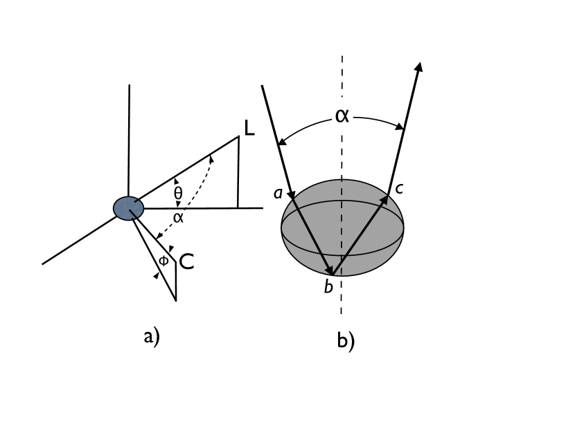
Figure 1 shows the geometry used to photograph the falling drops. The vertical axis is the direction of the velocity of the falling drop. The drop is symmetric about this axis but distorts along this axis taking on alternate prolate and oblate shapes. The light source is located at L at an angle above the horizontal plane and the camera at C at angle above the horizontal plane. The angle is the angle between the observer a C and the light source at L. Panel b) shows the path of the rays inside the drop that form the strongest reflected image. Rays enter the drop at a) and are reflected at the back surface at b) and emerge at c). For a drop flattened along the vertical line (dashed line) the rays entering near the edge as shown can undergo total internal reflection at b) giving rise to an intense backscattered beam.
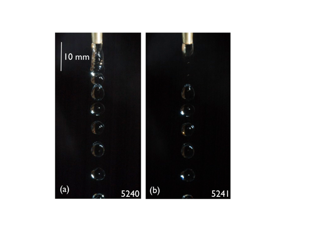
Figure 2 shows a sequence of stroboscopic images of two falling water drops. The flow rate is such that a drop has moved out of the field of view at the bottom of the picture before the next drop is released from the faucet. This is shown clearly in panel b). The drops are illuminated with an off-camera flash (Nikon 8600), operating in a repetitive mode yielding flashes at intervals separated by 10.0 ms. The orientation of the light and the camera are such that the flash angle is about 30 degrees the camera axis angle is 8 degrees. The camera to flash angle is about 30 degress. For best results the flash-to-camera angle should be from 30 to 50 degrees. From a study of hundreds of photographs such as the one in Fig. 1 one finds that initially, when the drop is released, it has an oblong, prolate shape as expected, and that it oscillates with a period of 30 ms between this shape and the pancake-like oblate form becoming spherical between these extremes. The peak to peak amplitude of these quadrupole oscillations is small but can be measured on the photograph to be about 10 % of the drop diameter.
In panel a) the strobe light starts before the drop is released. According to previous studies peregrine90 ; degennes when the liquid bridge between the drop and the faucet is broken, the drop has a prolate shape and the stored elastic energy sets up quadrupole oscillations along the vertical axis. Panel b) shows a sequence that starts once full cycle after the break of the bridge where the drop has returned to the prolate shape. Half a cycle before this, as seen in panel a), the shape is oblate and a bright spot of light, characteristic signature of the oblate phase can be seen about 10 mm below the faucet. The second bright spot occurs 23 mm below the faucet. Panel (b) also shows faint images of small secondary droplets formed from the narrow neck of the liquid bridge.
We focus our attention on the very bright images seen at the lower left boundary of the drops in the oblate phase of the oscillations in Fig. 1. In both pictures several bright images can be seen, separated by two darker drops in each case. Since the period of our strobe flash is 10 ms these bright images of the drops are approximately 30 ms apart, equal to the period of the lowest quadrupole mode of the capillary oscillation. That these oscillations start with the release of the drop is clear from the spacial position of of the bright maxima, always at the same distance below the faucet. The weak reflections of the flash unit towards the top-right in all the images are the reflection on the outer surface of the drop which is acting as a convex mirror. This image is present in all the pictures of the drop as it falls including the completely spherical shapes.
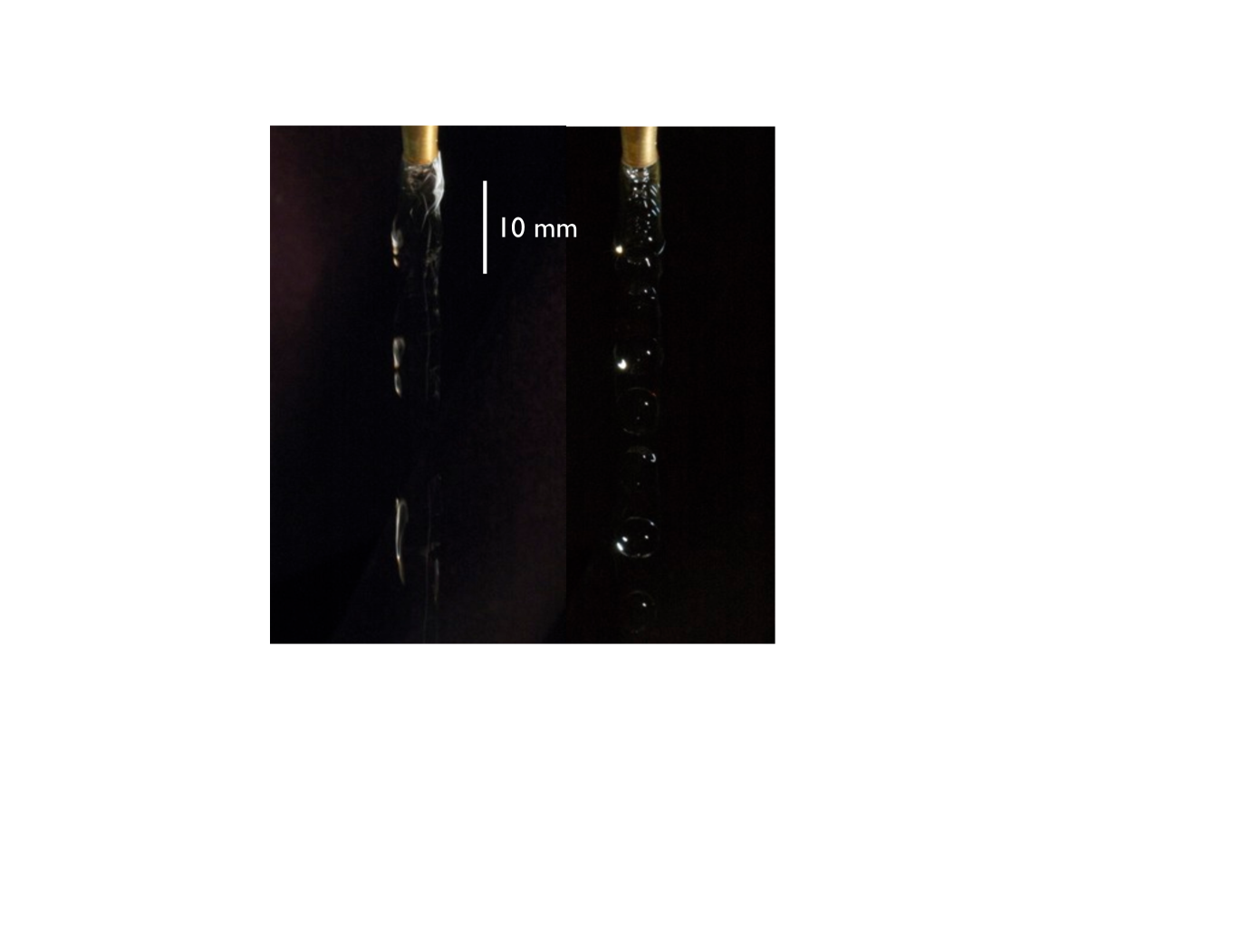
The bright flashes of light can be also photographed by a much simpler arrangement with a camera on a tripod, against dark background with a one second time exposure. Figure 3 shows one such time exposure on the left along with a stroboscopic picture of the drops on the right. Here the incident beam is at deg and the camera at . The scattering angle deg. Three strips of light can be seen centered at 8, 20.5 and 39 below the faucet. It is also clear that the bright phase of the oscillation is quite long, lasting approximately for half of the full cycle and that the bright streak occurs in the oblate phase. If one moves the camera further from the source one finds that the bright phase gets shorter and shorter. When the angle exceeds a critical value, roughly 60 degrees the bright streaks disappear completely and the water stream is black.
To further test the hypothesis that these are capillary oscillations we repeated our experiment with methyl alcohol. Methyl alcohol has a surface tension of only 22.6 mN/m. The main effect of this is a smaller drop; we measured a diameter 3.6 mm. It also has a lower density Kg/m3 at 20 C. These factors largely cancel the lower surface tension in Rayleigh’s formula resulting in a calculated period of 31.6 ms, only slightly larger than for water drops. Indeed, our experiments show that although the alcohol drops are much smaller than water drops, the bright images of methyl alcohol drops occur in the same place within the accuracy of our photographs as those of water drops.
III Discussion
What causes the bright flash of light in the oblate phase of the drop? The position of the light on the drop and its angular location relative to the flash suggests that the light originates from a single internal reflection, the same path that the primary rainbow image takes shown in Fig. 1b. This is the term in the Debye series used to discuss diffraction phenomena in small drops. li07 To investigate in detail the effect of the non-spherical shape of the drop on the intensity of the reflected light we wrote a ray tracing program that uses geometrical optics to follow the path of 200,000 parallel rays incident on an ellipsoidal drop falling on random positions on the surface of the drop and with random polarizations. At each surface we calculated the reflected and transmitted electric fields for using Frensel’s equations for and polarizations. We sorted the outgoing rays into bins according to scattering angle , i.e. the angle between the light source and the observer and the angle around the circle. Since the size parameter in our drops is 4600, we feel justified to use geometrical optics limit of scattering to model the propagation of light inside the drop and our method is only valid in the limit of drop size that is much larger than the wavelength.bohren ; wang91
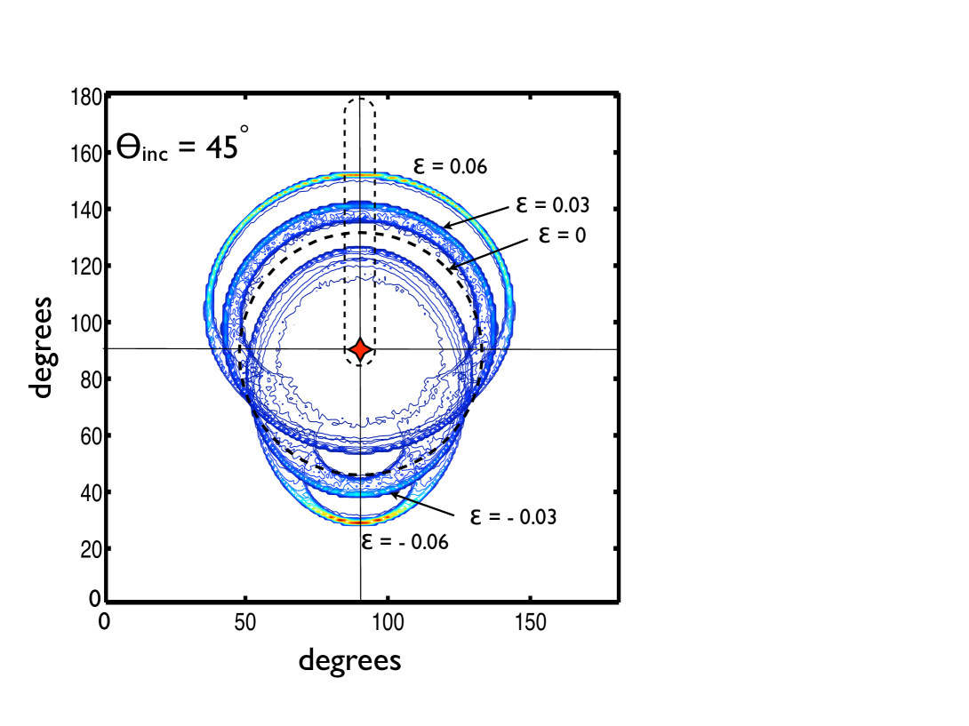
Figure 4. shows the calculated pattern of scattered light from the reflection as a function of vertical and horizontal angle. The incident direction is 45 degrees above the horizontal plane and the symmetry axis of the drop is vertical. The coordinates have been rotated in such a way as to place the incident direction in the center of the diagram. A conventional rainbow, in this diagram, would be a circle with a radius of 42 degrees centered on the incident direction. It is shown as a dashed circle. The back scattering from ellipsoidal drops forms elliptical ”rainbows”. The curves are for eccentricities ranging from to where the axes of the ellipsoid are with for the oblate shape and for the prolate shape. The major axis of oblate drops is horizontal and prolate drops vertical. At 45 degree angle of incidence shown in the figure the centers of the ellipses are displaced from the incident direction. Other angles of incidence also produce elliptical patterns. For example for light entering close to the symmetry axis the images are circles with larger radii in the oblate phase. For light entering normal to the symmetry axis, it i.e. the horizontal plane for falling drops, the images are ellipses with the major axis vertical but centers displaced from the horizon.
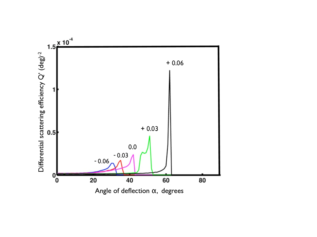
The scattering efficiency is defined as the ratio of the scattered flux to incident flux on a particle. bohren In Figure 5 we plot the scattering efficiency per unit solid angle i.e. the differential scattering efficiency of light scattered from ellipsoidal drops as a function of scattering angle along a great circle intersecting the symmetry axis of the drop i.e. the north pole of the flattened earth-like ellipsoidal drop. The region of angles covered is shown in Figure 4. The incident angle is 45 above the horizontal plane. For a spherical drop, the once internally reflected rays form a sharp peak at and there are no rays with . All the curves are cut off at a maximum angle . Angles larger than are in what for conventional rainbows are called the Alexander’s dark band. As we see, increases dramatically with increasing flatness of the drop from 42.4 degrees for a spherical drop to over 60 degrees for the most oblate drop. Also, we see an increase in overall intensity of the reflected light with increasing flatness. For the spherical water drop , i.e. 4 % of the incident energy on the ellipsoid is goes to the rainbow image. We contrast this with the oblate ellipsoid at 45 degree angle of incidence and where , substantially larger. However the efficiency is much stronger close at the angle of the caustic and extends over a much broader angle for the oblate shaped drop.
Ray tracing also shows that the brightness of the image seen in oblate drops is enhanced by a geometric effect caused by the elliptic shape of the drop which leads to an angle of incidence greater than degrees for for the reflection on the back surface of the drop. This is the condition for total internal reflection (TIR). Thus an oblate drop, illuminated from above, gives rise to a bright image from TIR light at the edge of the drop. A spherical drop does not give rise to TIR images. Prolate drops can also give rise to TIR and these can be seen for incident angles close to the horizontal symmetry plane of the drop.
Figure 5 also shows why the observer sees strips of light from a single oscillating drop. Situated at a fixed angle to the source, say where the angle of deflection deg, as the drop changes its shape no light is seen when the drop is in Alexander’s dark band. But whenl the eccentricity becomes positive a strong scattered beam is seen for . Fig. 6 also shows that the length of the bright phase depends on the scattering angle getting shorter for large scattering angles. The length of the bright phase in Fig. 3 is consistent with 50 deg scattering angle used in the experiment.
It is important to note that large water drops, drops that are larger than the wavelength of light, do not scatter much light. Viewed from any angle except right into the light source they will appear black. This can be seen clearly in fig. 2. Geometrical optics of a sphere shows that the reflected image from the front surface has 6.6 % of the incident intensity while 88.4 % goes to the transmitted beam. The internally reflected beam, the one that forms the rainbow, has only 4.0 % intensity. These three rays account for 99.7 % of the incident intensity deflected by a spherical drop bohren .
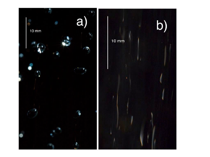
Why then do water sprays appear white? A close inspection of any such spray suggests the answer. Observed visually with an overhead light source it is clear that the spray consists of short strips of bright light. A flash photograph of a bath shower, shown in Fig. 6, shows that while most of the drops are indeed black as predicted by geometrical optics of a sphere, there are some very bright drops that provide the light. The photograph also shows that while most drops are spherical in shape many are quite irregular. Nevertheless, the strips of bright light are more or less the same length and can be seen as far as 2 m from the shower head. The strips are not seen in diffuse light confirming the idea that the scattering is caused by geometrical optics of the drops and not multiple isotropic scattering as seen in clouds. A typical spray is optically thin. It is clear that the same phenomenon of capillary oscillations of droplet shape giving rise to strips of light below the dripping faucet is favorable towards strong scattering of light in all sprays . It is surprising that this common phenomenon is rarely discussed in the literature although we found a photograph of rainfall in ref. (4) where the author does interpret the bright traces due to capillary oscillations and estimates the drop size using Rayleigh’s formula. But as Fig. 6 shows the location of the bright image varies from drop to drop which makes any quantitative study of the optics of sprays difficult. In a spray the oscillations are driven by turbulence and are a complex combination of rocking and zig-zag motions combined with the capillary oscillationsclift . In contrast, the dripping tap provides a system with well defined starting conditions for the oscillations.
Finally returning to the rainbow one has to note that it is generally assumed that falling raindrops that are large will be flattened due to air resistance and undergo capillary oscillations.volz . However as the present study shows, such drops cannot give rise to a conventional rainbow. The p=2 caustic varies in angle from 30 to 60 degrees in the course of one cycle completely washing out any wavelength dependent dispersion that requires stability of the rainbow angle to better than one degree. We conclude that only very small, non-oscillating drops can give rise to colorful rainbows.
In summary, experiments show that large water drops scatter light strongly in the oblate phase of capillary oscillations. We suggest that this effect is also responsible for the strips of light seen in most sprays and ultimately for their white color when illuminated by a fairly concentrated overhead source. We also suggest that any realistic computer simulation of water sprays be in the form of bright strips of light in the direction of the flow of the spray. Another application of the phenomenon is to Fourier transform the light scattered by the spray and use the resulting peak at the Rayleigh frequency to determine average drop size optically.
Acknowledgements
This work has been supported by the Canadian Natural Science and Engineering Research Council and the Canadian Institute of Advanced Research. We would like to acknowledge valuable suggestions by Kari Dalnoki-Veress and technical help by Andy Duncan and Greg Egan.
References
- (1) René Descartes, Discourse of the Method (1637).
- (2) C.E. Bohren and D.R Huffman Absorption and scattering or light by small particles, (Wiley-Interscience, 1983).
- (3) P.L. Marston, ”Rainbow phenomena and the detection of nonsphericity in drops,” Applied Optics, 19, 680-689 (1980).
- (4) Rayleigh, Phil. Mag. (5) xxxiv. 177 (1892), H. Lamb Hydrodynamics, 6th. ed. (Cambridge University Press (1932) p. 473.
- (5) Ph. Lenard, “Über die Schwingungen fallender Tropfen,” Ann. Phys. Chem., 30, 209 (1877).
- (6) F.E. Volz, ”Some aspects of the optics of the rainbow and the physics of rain,” Physics of Precipitation ed. by H. Weickmann, American Geophysical Union monograph No. 5, 280-286 (1960).
- (7) P-G. de Gennes, F. Brochard-Wyart, D. Qu r , A. Reisinger Capillarity and Wetting Phenomena: Drops, Bubbles, Pearls, Waves, Springer, New York, 2004.
- (8) S. Chandrasekhar, “The oscillations of a viscous liquid globe,” Proc. London Math. Soc. 9, 141- 149 (1959).
- (9) D.H. Peregrine, G. Shoker, A. Symon, “The bifurcation of liquid bridges,” J. Fluid Mech. 212. 25-39 (1990).
- (10) Renxian LI, Xiang e Han, Lijuan Shi, Kuan Fang Ren, and Huifen Jiang, “Debye series for Gaussian beam scattering by a multilayered sphere”, App. Optics 46, 4808 (2007).
- (11) Ru T. Wang and H. C. van de Hulst, App. Optics 30 106 (1991), “Rainbows: Mie computations and the Airy approximation”
- (12) R. Clift, J.R. Grace and M.E. Weber, Bubbles drops and Particles, Academic Press, New York 1978, p. 185.