Detector Optimization for SiD using PFA
Abstract
A summary of the optimization of the SiD detector is given. To optimize its performance in terms of Particle Flow Algorithms (PFA) , five basic detector parameters have been varied and the impact on the obtained energy resolution using Particle Flow Algorithms has been studied using di-jets events. Finally the optimized detector used for the Letter of Intent (LoI) is briefly summarized as a result from these studies.
1 Introduction
The SiD detector[1] concept for the ILC111International Linear Collider has been designed with the Particle Flow Algorithm approach in mind. The PFA approach actually drives a lot of the design choices such as locating the highly granular calorimetry within the superconducting coil. In order to maximize the performance of the SiD detector concept, events were simulated using several different detector variants and these events were run through the full PFA chain. This allowed us to choose an optimal configuration for PFA while keeping other constraints like engineering or costs in mind. The quantity being optimized is the Jet Energy Resolution, which maximizes the physics potential of the SiD detector.
The SiD detector (sid01) consists of a 5-layer Vertex Detector using Silicon pixels, a 5 layer tracker using silicon strip detector, a 30 layer electromagnetic calorimeter (ECAL) using Silicon-Tungsten, a 34 layer hadronic calorimeter (HCAL) using Iron and RPC’s222Resistive Plate Chambers. Outside of the HCAL is the 5 T solenoid and the Muon system integrated in the iron flux return yoke.
2 The Software Setup
LDC00Sc SiDish ECAL inner radius 1.7 m 1.25 m ECAL length 2.7 m 1.7 m ECAL layers 30+10 20+10 ECAL material SiW SiW HCAL layers 40 40 HCAL material Fe-Scint Fe-Scint B Field 4 T 5 T
The PFA algorithm chosen for this study is PandoraPFA 2.01[2], which has been developed by Mark Thomson. This requires the use of the Mokka package[3] for the GEANT4[4] based detector simulation and Marlin[5] for event reconstruction and not SiD’s tool chain of SLIC[6] for the detector simulation and org.lcsim for the event reconstruction. As there is currently no accurate SiD detector simulation available within Mokka, a SiD-look-alike, the SiDish has been derived from the LDC00Sc model available in Mokka. The LDC00Sc model is using the old TESLA detector design [7]. As the calorimetry is the largest cost driver of any PFA-based ILC detector, a detector which such a deep and long calorimeter is considered to be too expensive to be an realistic option. E.g. scaling up the ECAL increases its volume by a factor of 2.7.
Since the LDC00Sc model has a TPC333Time Projection Chamber and there was also no all-silicon tracking software available at the time, the TrackCheater from the MarlinReco package was used. For the GEANT4 physics list, we used the LCPHYS list, which has been recommended by WWS Software panel. The parameters of the simulated SiDish detector are shown in Tab. 1.
It should be emphasized, that there are still fundamental differences in e.g. the HCAL, as SiD uses a digital HCAL with RPC’s for the readout instead of the scintillator readout in SiDish. Also there are differences in the general calorimeter layout and the tracker material distribution. So one should only consider SiDish as an approximation of SiD in the framework of this study.
3 Results
The coordinate system of SiD follows the general coordinate system of many HEP detectors, with the z-axis set to be along the beam axis. In this study, five main detector parameters have been studied:
-
1.
Magnitude of the B Field
-
2.
ECAL inner Radius
-
3.
ECAL inner length in z
-
4.
HCAL depth in
-
5.
HCAL longitudinal segmentation
In all studies we have used events at various energies unless mentioned otherwise. To measure the performance we use (in percent) as defined in
| (1) |
and as used by Thomson[2]. SiD has a 5 T field as baseline since the high field it is beneficial for tracking and vertexing and helps suppressing the beam background.
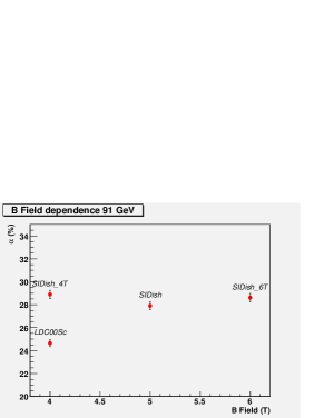
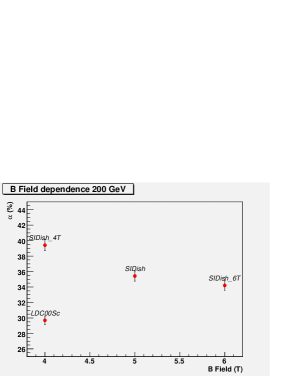
3.1 The B field magnitude
To study the impact of the B-Field, several versions of SiDish have been simulated with a B field from 4-6 T. The impact of the B field on the PFA performance is shown in Fig. 1. For a compact detector design like SiD, a 5 T field is to be preferred over a 4 T field from the point of view of both PFA and tracking performance[1].
3.2 The inner radius of the ECAL
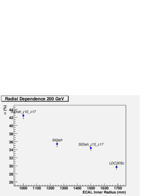
Due to the choice of a 5 T B field, the space inside the coil is limited due to material and engineering constraints, leading to a maximum inner radius of the ECAL of about 1.5 m. For this study the inner radius of the ECAL was varied between 1.0 and 1.5 m using both events at =91 and 200 GeV (see Fig. 2). For a 5 T field, increasing the radius to 1.5 m only leads to a small gain, however decreasing the inner radius of the ECAL to 1.0 m has a quite sizeable impact on the PFA performance.
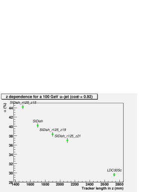
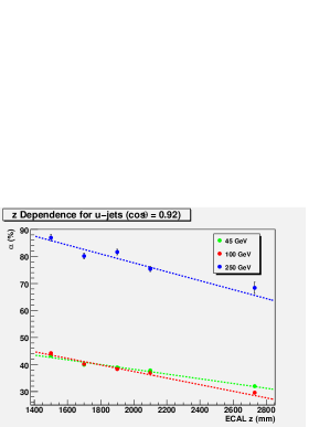
3.3 The inner length of the ECAL
In this study a single u-quark with an energy of 45, 100 or 250 GeV was fired at a fixed angle of =0.92 and then fragmented. This allows the study the impact of inner z of the ECAL or in other words the impact of the length of the tracker. The results from this study are shown in Fig. 3. It can be clearly seen that a longer detector is beneficial for PFA.
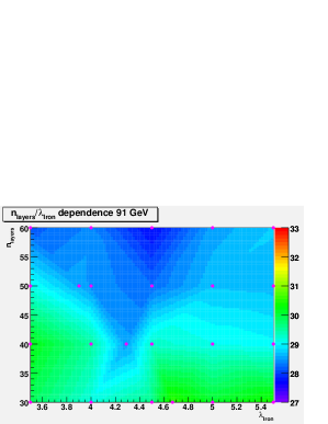
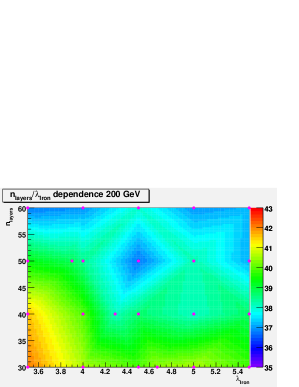
3.4 The optimization of the HCAL
For the HCAL, the depth in terms of and the number of layers were both simultaneously optimized leading to about 36 different detector configurations that have been evaluated, where both the thickness of the iron absorber was varied between 3.5 and 5.5 and the number of readout layers was varied between 30 and 60 layers. The detector baseline (sid01) only had 34 HCAL layers with 4.0 . From Fig. 4 it is clear that a deeper HCAL is beneficial for higher energies, however keeping engineering constraints in mind, a 40 layer HCAL with 4.5 is an optimum for SiD.
4 The optimized SiD detector
All the results shown before and input from other studies[8] lead to two optimized detector variants, sid02 and sid02-stretch. The parameters of both are shown in Tab. 2. The variant with the longer barrel has superior performance in the forward region which ranges from 2.5 - 4 % (absolute) in the forward region, but due to engineering concerns, SiD conservatively chose sid02 as the detector to use for the LoI.
sid01 sid02 sid02-stretch ECAL inner radius (m) 1.25 1.25 1.25 ECAL inner Z (m) 1.7 1.7 2.1 HCAL depth () 4 4.5 4.5 HCAL layers 34 40 40 B Field (T) 5 5 5
5 Conclusions and Outlook
SiD has converged on an optimized detector for the LoI however the LoI will not be the end of these studies. As SiD now has also a PFA algorithm[9] in the org.lcsim framework, a lot of these studies will continue using SiD’s own simulation and reconstruction framework. There will be continuous work in exploring stretched detector designs with improved forward performance. The current detector versions captures the current knowledge and lays out a route for the post-LoI phase of SiD.
6 Acknowledgments
I would like to thank the SiD-PFA group for all their contributions and M. Breidenbach, J.Jaros, M. Thomson, A. White and H. Weerts for useful discussions on optimizing SiD.
References
-
[1]
The SiD detector outline document
http://hep.uchicago.edu/~oreglia/siddod.pdf - [2] M. Thomson, Particle flow calorimetry, J. Phys. Conf. Ser. 110 (2008) 092032.
- [3] P. Mora de Freitas, Prepared for International Conference on Linear Colliders (LCWS 04), Paris, France, 19-24 Apr 2004.
- [4] S. Agostinelli et al. [GEANT4 Collaboration], Nucl. Instrum. Meth. A 506 (2003) 250.
- [5] F. Gaede, Nucl. Instrum. Meth. A 559 (2006) 177.
- [6] N. Graf and J. McCormick, AIP Conf. Proc. 867 (2006) 503.
- [7] T. Behnke, S. Bertolucci, R. D. Heuer and R. Settles, “TESLA: The superconducting electron positron linear collider with an integrated X-ray laser laboratory. Technical design report. Pt. 4: A detector for TESLA,”
- [8] M. Breidenbach private communcation.
- [9] M. J. Charles, “PFA Performance for SiD,” arXiv:0901.4670.