Spin currents and magnetoresistance of graphene-based magnetic junctions
Abstract
Using the tight-binding approximation and the nonequilibrium Green’s function approach, we investigate the coherent spin-dependent transport in planar magnetic junctions consisting of two ferromagnetic (FM) electrodes separated by a graphene flake (GF) with zigzag or armchair interfaces. It is found that the electron conduction strongly depends on the geometry of contact between the GF and the FM electrodes. In the case of zigzag interfaces, the junction demonstrates a spin-valve effect with high magnetoresistance (MR) ratios and shows negative differential resistance features for a single spin channel at positive gate voltage. In the case of armchair interfaces, the current-voltage characteristics behave linearly at low bias voltages and hence, both spin channels are in on state with low MR ratios.
I Introduction
Spin-dependent transport through magnetic nanojunctions is currently receiving increased attention owing to the expectation that nanoscale size constraints may maximize the potentially useful magnetoresistance effects. Among various types of nanoscale devices, carbon-based nanostructures are attractive for spin-polarized electronics Wolf ; Moodera because the relatively weakness of spin-orbit and hyperfine interactions should lead to long spin coherence times Sanvito . In particular, the spin-dependent transport studies on carbon nanotubes coupled to ferromagnetic Co electrodes have shown that nanotubes exhibit a considerable tunnel MR effect Tsukagoshi ; Chakraborty . A C60 molecule is also an interesting nanocarbon unit, and recently the spin-dependent electron transport for the granular film consisting of Co nanoparticles embedded in a Co-C60 compound matrix has been studied, and the maximum MR ratio of about 30% at low bias voltages was reported Zare ; Sakai ; Miwa .
Another related carbon-based structure is graphene which demonstrates many useful electronic properties: high carrier mobility, long spin relaxation times and lengths, extreme flexibility and stability, and metallic properties controllable by a gate electrode Novoselov ; Geim . Moreover, due to the flat structure, graphene seems to be easier to manipulate than carbon nanotubes. Furthermore, interesting properties appear if the graphene is patterned into ribbon like geometry called the graphene nanoribbon (GNR). For instance, they can be either semiconducting with a size dependent gap or metallic Han . Transport properties of GNRs are expected to depend strongly on whether they have an armchair or zigzag edge Nakada . In GNRs with zigzag edges, transport is dominated by edge states which have been observed in scanning tunneling microscopy Kobayashi . These states are expected to be spin-polarized and make zigzag GNRs attractive for spintronics Prinz ; Wolf .
Based on first-principles calculations, Son et al. Son predicted that the zigzag GNRs become half-metallic when an external transverse electric field is applied. Using such calculations, Kim and Kim Kim showed that zigzag GNRs connected to two ferromagnetic (FM) electrodes exhibit very large values of magnetoresistance. Using the tight-binding approximation, Bery and Fertig Bery studied the magnetoresistance of GNR-based spin valves in the infinite width limit. They reported a feeble magnetoresistance due to the weak dependence of the graphene conductivity on the electronic parameters of the FM leads. The other spin-dependent properties of graphene such as spin field effect transistor Semenov , spin Hall effects Kane ; Sinitsyn , and magnetic ordering in graphene Okada have also been predicted.
Experimentally, based on the nonlocal magnetoresistance measurements, spin injection into a graphene thin film connected to FM electrodes has been successfully demonstrated Tombros ; Cho ; Ohishi and the possibility of spin transport and spin precession over micrometer-scale distances at room temperature reported Tombros . Hill et al. Hill have observed large magnetoresistances of several hundred ohms in a spin-valve device where a 200 nm wide graphene wire is contacted by two soft magnetic NiFe electrodes. Also, Wang et al. Wang have investigated magnetotransport properties of spin valves consisting of graphite flakes connected to FM electrodes, and the magnetoresistance values up to 12% at 7 K were observed when an ultrathin MgO tunnel barrier was inserted at the FM/graphite interface. These experiments clearly demonstrate the possibility of spintronics applications for graphene.
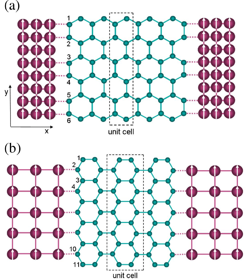
In this paper, we present a theory to investigate the spin-dependent properties of planar magnetic junctions consisting of a graphene flake (GF) connected by two FM electrodes in the presence of bias and gate voltages. A GF is a finite rectangular GNR with finite number of carbon atoms and, therefore, it can be coupled to the two square-lattice FM electrodes through its armchair or zigzag edges Robinson ; Blanter . Such configurations have been shown in Fig. 1. The present approach indicates that the spin-polarized transport in such magnetic junctions is mainly controlled by the molecular field of the FM electrodes, the geometry of FM/GF interface, bias and gate voltages, and the strength of FM/GF coupling.
The paper is organized as follows. In Sec. II, we present the model and formalism for spin transport through FM/GF/FM magnetic junctions where the interfaces between FM leads and GF can be armchair or zigzag. Numerical results and discussions for transmission coefficients, spin currents and magnetoresistance are presented in Sec. III. We conclude our findings in Sec. IV.
II Model and formalism
We consider a system which consists of a rectangular GF with armchair and zigzag edges, and two square-lattice FM electrodes. The GF can be coupled to the magnetic electrodes in such a way that their interface is armchair or zigzag. The two models for such structures are shown schematically in Fig. 1. Since the electron conduction is mainly determined by the graphitic region, the electronic structure of this part should be resolved in detail. Hence, we decompose the total Hamiltonian of the system as
| (1) |
where and are the Hamiltonians of the left () and right () electrodes, describes the Hamiltonian of the graphitic region (GF), and is the coupling of the GF to the electrodes. All terms of the total Hamiltonian are described within the single-band tight-binding approximation and can be written as
| (2) |
| (3) |
| (4) |
where () and () create (annihilate) an electron with spin on site in the electrodes and the graphitic region, , , and if and are nearest neighbors and zero otherwise. , the on-site energy of the electrodes, is equal to which acts as a shift in energy, and , the on-site energy of the GF, is zero except in the presence of gate voltage , that shifts the energy levels of the GF. Here, is the internal exchange energy with denoting the local magnetization at site , and being the conventional Pauli spin operator.
In this study we set and assume that the transport is ballistic Datta ; hence, we set , because the value of should not be smaller than the order of . Such a ballistic approximation is valid when the mean free path of the carriers is greater than the sample dimensions. High mobility of charge carriers in graphene, even at room temperature, implies that carriers can move long distances without scattering Novoselov . Hence, we expect that the ballistic approximation to be appropriate in studying transport in GFs. In addition, we assume that the spin direction of the electron is conserved in the tunneling process through the graphitic region. Therefore, there is no spin-flip scattering and the spin-dependent transport can be decoupled into two spin currents: one for spin-up and the other for spin-down. This assumption is well-justified since the spin diffusion length in organics is about 4 nm Sanvito and especially in carbon nanotubes is at least 130 nm Tsukagoshi and in graphene is 1.5 m Jozsa , which are greater than the length scale of our device. Since the total Hamiltonian does not contain inelastic scatterings, the spin currents for a constant bias voltage, , are calculated by the Landauer-Büttiker formula based on the nonequilibrium Green’s function method Datta :
| (5) |
where is the Fermi-Dirac distribution function, are the chemical potentials of the electrodes, and is the spin-, energy- and voltage-dependent transmission function. The spin-dependent Green’s function of the graphitic region coupled to the two FM electrodes (source and drain) in the presence of the bias voltage is given as
| (6) |
where and describe the self-energy matrices which contain the information of the electronic structure of the FM electrodes and their coupling to the GF. These can be expressed as where is the hopping matrix that couples the graphene to the leads and depends on the geometry of the FM/GF interface. are the surface Green’s functions of the uncoupled leads i.e., the left and right semi-infinite magnetic electrodes, and their matrix elements are given by
| (7) |
where is a positive infinitesimal, , and
| (8) |
Here, () is an integer, , and with is the number of lattice sites in the direction. Using , the coupling matrices , also known as the broadening functions, can be expressed as .
When the GF is brought close to an electrode, the bonding between them will depend on the arrangement and the nature of the atoms at the FM/GF interface. In Fig. 1(a), the graphitic region consisting of 5.5 unit cells is matched to the FM leads along its armchair edges. In this case, the lattice constant of the leads, , is equal to the lattice constant of the GF, . On the other hand, if two FM electrodes are coupled to the graphene along its zigzag edges, we obtain Fig. 1(b) where and the GF consists of 3 unit cells. In both junctions, there is the same number of carbon atoms at the graphitic part, while the number of contact points at the FM/GF interfaces has decreased from six (in Fig. 1(a)) to five (in Fig. 1(b)). Therefore, one can expect different spin transport through the GF, which will be discussed in the next section. We should note that, the core of the problem lies in the calculation of the spin-dependent self-energies and . In this regard, for a GF with carbon atoms and in the case of contact through () carbon atoms at the armchair (zigzag) interfaces, only () elements of the self-energy matrices will be non-zero.
III Results and discussion
We now use the method described above to study the coherent spin-dependent transport and magnetoresistance effect of FM/GF/FM junctions with armchair and zigzag interfaces. We have done the numerical calculations for the case that the direction of magnetization in the left FM electrode is fixed in the + direction, while the magnetization in the right electrode is free to be flipped into either the + or - direction. We choose a GF with =66 carbon atoms and set =1 eV, =0.75 eV, =0.0 eV, and =300 K in the calculations.
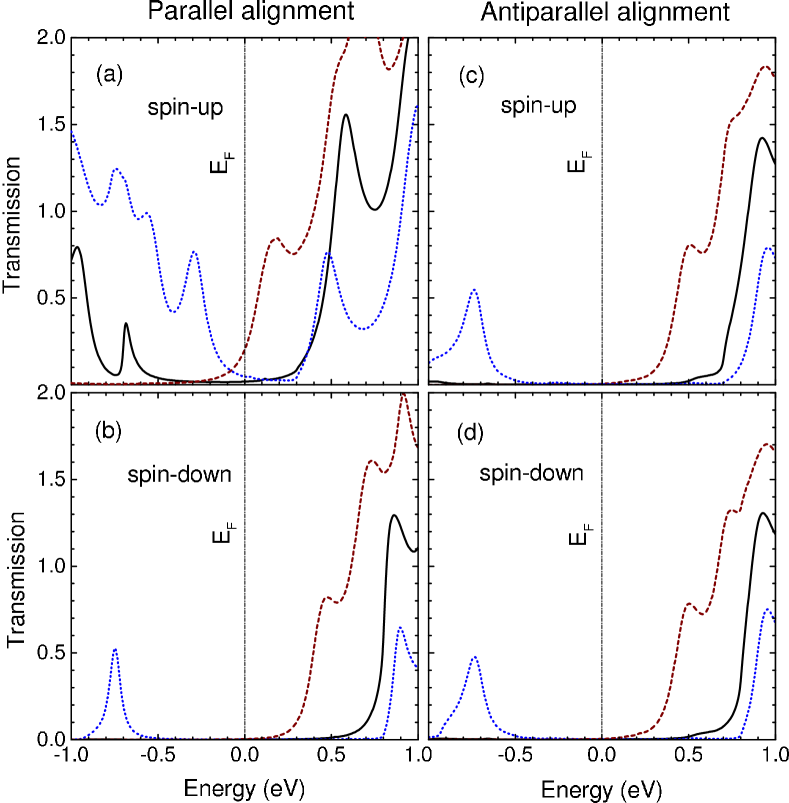
In Figs. 2 and 3 we depict the spin-dependent transmission coefficients for the junctions with zigzag (=5) and armchair (=6) interfaces, respectively. Only the energy window around the Fermi level has been shown. In these figures, the transmission characteristics clearly demonstrate the dependence of electron conduction on the geometry of contact between the FM electrodes and the GF. In the case of parallel alignment of the junction with zigzag interfaces, there are non-zero transmissions only for spin-up electrons (on state) and the spin-down ones are in off state. In the case of antiparallel alignment, both spin channels are in off state. This is the so-called spin-valve effect or magnetoresistive effect and indicates that, the junction with zigzag interfaces can work as a switch, or a bit with on and off states. The spin-valve devices are promising candidates for systems that may transform spin information into electrical signals.
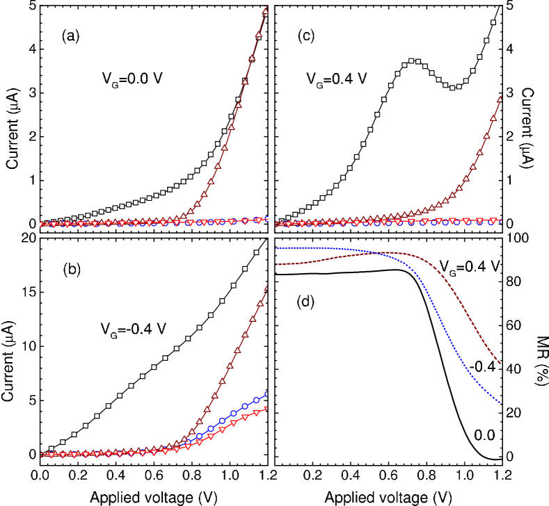
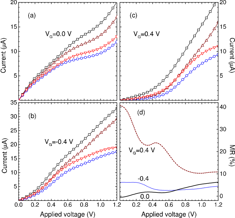
From the spin-dependent currents of the junction with zigzag interfaces it is clear that at low applied voltages ( V) only the spin-up current in the parallel alignment is in on state (see Figs. 4(a)-(c)). The current-voltage characteristics of such electrons are linear at low voltages and display different behaviors at higher voltages, depending on the value of gate voltage. One interesting feature of the - characteristics is that the spin-up current for =0.4 V shows a negative differential resistance region which is visible as a decrease in the current upon increasing Dragoman . This behavior is due to a gradual disappearance of a resonant level within the voltage window in that region. In addition, the appearance of zero current and the necessity of threshold voltage to generate finite current flow through the junction in some of the - curves, arising from the energy mismatch between the Fermi energy of the FM electrodes and the lowest unoccupied levels of the GF.
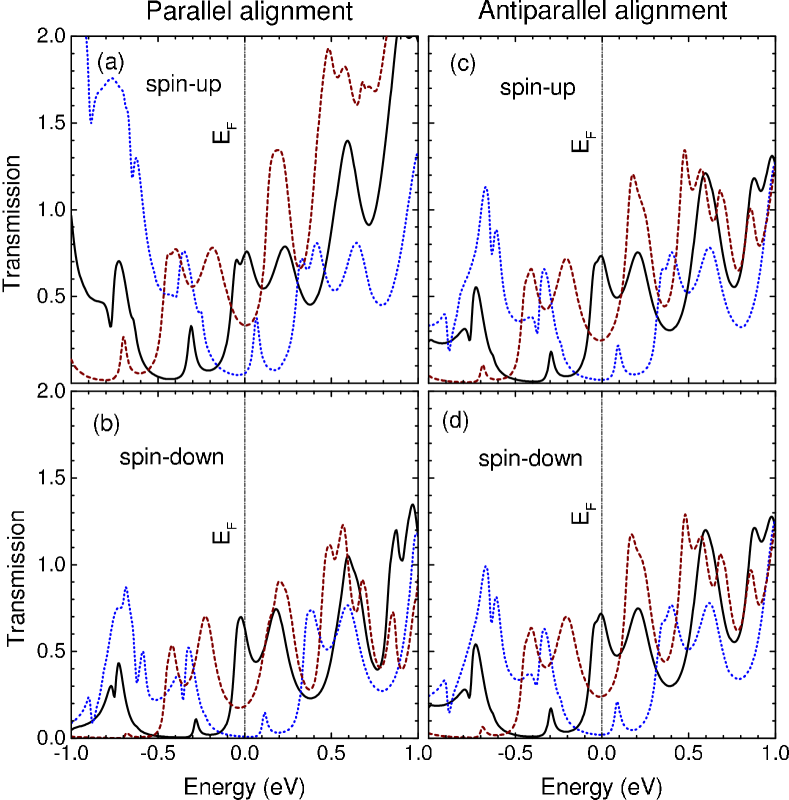
Interestingly, as shown in Fig. 3, the calculated transmission coefficients of two spin channels in both magnetic alignments are significantly larger than the transmission spectra of Fig. 2 near the Fermi energy and thus according to Figs. 5(a)-(c) our theory predicts a linear behavior in the - characteristics at low bias voltages for the junction with armchair interfaces. In contrast to the spin currents of the junction with zigzag interfaces, none of the spin currents exhibits a gap in the - characteristics of Fig. 5, which is due to the existence of the resonant states near the Fermi energy in the junction with armchair interfaces.
The main factor of difference in the calculated transmission spectra arises due to the quantum interference effects. In the case of armchair interfaces, the current flow mechanism corresponds to the resonant tunneling which can be attributed to Fabry-Pérot interference of electronic states partially reflected from the electrodes, due to the finite length of the graphene sample Blanter . In the case of zigzag interface, however, the interference between electronic waves scattered by the carbon atoms along the FM/GF interfaces becomes important, some resonances might completely disappear, and the transmission curve changes (compare Fig. 2 with Fig. 3). Therefore, the current flow mechanism is tunneling. The physical meaning of the interference effect is that the electron waves in the GF which come from the FM electrode may suffer a phase shift. Thus, a constructive or destructive interference in the propagation process of the electron through the GF can occur.
Another interesting feature of the junctions is the magnetoresistance ratio which can be obtained from the - curves using the definition: , where are the total currents in the parallel and antiparallel alignments of magnetizations in the FM electrodes, respectively. In Figs. 4(d) and 5(d) we have shown the MR ratios for the two junction at positive and negative gate voltages. It is clear that the MR in the junction with zigzag interfaces has high values in comparison with the other junction. The origin of magnetoresistance effect is the difference in the total currents which is related to the asymmetry of surface density of states of the FM electrodes for spin-up and spin-down electrons and the quantum tunneling phenomenon through the GF. In the parallel alignment, minority (majority) electrons in the left FM electrode go into the minority (majority) states of the right one by tunneling through the GF. If, however, the two FM electrodes are magnetized in the opposite directions, the minority (majority) electrons from the left electrode seek empty majority (minority) states in the right electrode. Consequently, the parallel arrangement gives much higher total current through the GF than does the antiparallel arrangement in the selected voltage interval except for zero gate voltage at high (low) applied voltages for the junction with zigzag (armchair) interfaces.
We also studied the effect of on the spin currents and MR ratio. The results showed that in both junctions, the values of currents increase with increasing (from 0.5 to 1 eV), while the MR values do not change considerably due to its relation to relative change of total currents between both magnetic alignments.
Now we present a discussion on the spin states at the edges of GF. As we pointed out, zigzag edge GNRs present half-metallic behavior when homogeneous electric fields are applied across the ribbons (in our model, along the direction of Fig. 1(a)). This behavior is related to the existence of electronic states at the Fermi energy spatially localized at the zigzag edges. The ground-state spin configuration at zero electric field corresponds to an opposite spin orientation across the ribbon between the spin-polarized edge states. That is, the spins on the outermost sites of each zigzag edge are parallel, resulting in one edge polarized with spin up and the other polarized with spin down, and the total zigzag-GNR spin is equal to zero Son . In contrast, the armchair edge GNRs do not show such spin states due to the delocalized nature of the frontier orbitals Zhou . Theoretical studies have revealed that in zigzag GNRs; (i) the critical electric field to achieve half-metallicity decreases with the increase of ribbon width, (ii) the ribbon remains half-metallic only at a limited range of electric field, and (iii) the half-metallicity will be destroyed by a too strong electric field and the ribbon becomes nonmagnetic Son ; Kan ; Hod .
From a theoretical point of view, in order to observe the spin states due to the edge-localized states in the zigzag GNRs, one can use of first-principles calculations, which can predict the electrical and magnetic properties of a material from the atomic number and mass of its constituent atoms Son ; Kim ; Kan ; Hod ; Pisani , or include the electron-electron interaction in the total Hamiltonian Guo ; Rossier . The structure used in this study is analogous to that of Ref. [16]. However, we have used of the single-band tight-binding Hamiltonian in the absence of interactions, because in this work we are interested in the effects of the FM/GF interfaces on the spin transport. Hence, the results do not yield the spin states at the edges of zigzag ribbon [Fig. 1(a)]. According to the above discussion, such a restriction does not invalidate our model for the zigzag edge junction, since the electronic states corresponding to the edge states, as it is clear from Fig. 3, are far from the Fermi energy. The present theory demonstrates well the effect of magnetic states of the electrodes on the electron conduction through the GF, and also reveals well the role of contact geometry in the spin-polarized transport through the two above junctions. We should note that, if we include the interactions in our Hamiltonian, the magnetic states corresponding to the edges may affect the spin currents and the MR.
IV Conclusion
In this work, spin polarized transport of armchair and zigzag interfaces between a GF and FM electrodes (Fig. 1) is investigated in the tight-binding approximation. The results indicate that the atomic arrangement at the interface between the FM electrode and the GF has a dominant effect on the electron conduction through the graphene-based magnetic junctions. The planar FM/GF/FM junction with zigzag interfaces exhibits a spin-valve effect with MR values as high as 95% and negative differential resistance features for a single spin channel. In the case of armchair interface, both spin channels are in on state with low MR ratios. In addition, the results of bias and gate voltage dependence of the spin currents and MR have been reported.
In this study, we ignored the effects of spin states at the edges of GF and the magnetic anisotropy of the FM electrodes due to the reduced dimensionality and the geometry of the system. Although, these factors can affect the spin-dependent transport, the present study advances the fundamental understanding of interfacial effects in the graphene-based magnetic junctions and suggests that the junction with zigzag interfaces is an interesting candidate for application in the magnetic memory cells and spintronic devices.
References
- (1) S. A. Wolf, D. D. Awschalom, R. A. Buhrman, J. M. Daughton, S. von Molnár, M. L. Roukes, A. Y. Chtchelkanova, and D. M. Treger, Science 294, 1488 (2001).
- (2) J. S. Moodera, J. Nassar, and G. Mathon, Annu. Rev. Mater. Sci. 29, 381 (1999).
- (3) S. Sanvito, Nature Nanotechnology 2, 204 (2007).
- (4) K. Tsukagoshi, B. W. Alphenaar, and H. Ago, Nature (London) 401, 572 (1999).
- (5) S. Chakraborty, K. M. Walsh, B. W. Alphenaar, L. Liu, and K. Tsukagoshi, Appl. Phys. Lett. 83, 1008 (2003).
- (6) H. Zare-Kolsaraki and H. Micklitz, Eur. Phys. J. B 40, 103 (2004).
- (7) S. Sakai, K. Yakushiji, S. Mitani, K. Takanashi, H. Naramoto, P. V. Avramov, K. Narumi, V. Lavrentiev, and Y. Maeda, Appl. Phys. Lett. 89, 113118 (2006).
- (8) S. Miwa, M. Shiraishi, S. Tanabe, M. Mizuguchi, T. Shinjo, and Y. Suzuki, Phys. Rev. B 76, 214414 (2007).
- (9) K. S. Novoselov, A. K. Geim, S. V. Morozov, D. Jiang, Y. Zhang, S. V. Dubonos, I. V. Gregorieva, and A. A. Firsov, Science 306, 666 (2004).
- (10) A. K. Geim and K. S. Novoselov, Nature Mater. 6, 183 (2007).
- (11) M. Y. Han, B. Özyilmaz, Y. Zhang, and P. Kim, Phys. Rev. Lett. 98, 206805 (2007).
- (12) K. Nakada, M. Fujita, G. Dresselhaus, and M. S. Dresselhaus, Phys. Rev. B 54, 17954 (1996).
- (13) Y. Kobayashi, K. Fukui, T. Enoki, and K. Kusakabe, Phys. Rev. B 73, 125415 (2006); Y. Niimi, T. Matsui, H. Kambara, K. Tagami, M. Tsukada, and H. Fukuyama, Phys. Rev. B 73, 085421 (2006).
- (14) G. A. Prinz, Science 282, 1660 (1998).
- (15) Y.-W. Son, M. L. Cohen, and S. G. Louie, Nature (London) 444, 347 (2006).
- (16) W. Y. Kim and K. S. Kim, Nature Nanotechnology 3, 408 (2008).
- (17) L. Bery and H. A. Fertig, 76, 205435 (2007).
- (18) Y. G. Semenov, K. W. Kim, and J. M. Zavada, Appl. Phys. Lett. 91, 153105 (2007).
- (19) C. L. Kane and E. J. Mele, Phys. Rev. Lett. 95, 226801 (2005).
- (20) N. A. Sinitsyn, J. E. Hill, H. Min, J. Sinova, and A. H. MacDonald, Phys. Rev. Lett. 97, 106804 (2006).
- (21) S. Okada and A. Oshiyama, Phys. Rev. Lett. 87, 146803 (2001).
- (22) N. Tombros, C. Jozsa, M. Popinciuc, H. T. Jonkman, and B. J. van Wees, Nature (London) 448, 571 (2007).
- (23) S. Cho, Y.-F. Chen, and M. S. Fuhrer, Appl. Phys. Lett. 91, 123105 (2007).
- (24) M. Ohishi, M. Shiraishi, R. Nouchi, T. Nozaki, T. Shinjo, and Y. Suzuki , Jpn. J. Appl. Phys. Part 2 46, L605 (2007).
- (25) E. W. Hill, A. K. Geim, K. Novoselov, F. Schedin, and P. Black, IEEE Trans. Magn. 42, 2694 (2006).
- (26) W. H. Wang, K. Pi, Y. Li, Y. F. Chiang, P. Wei, J. Shi, and R. K. Kawakami, Phys. Rev. B 77, 020402(R) (2008).
- (27) J. P. Robinson and H. Schomerus, Phys. Rev. B 76, 115430 (2007).
- (28) Ya. M. Blanter and I. Martin, Phys. Rev. B 76, 155433 (2007).
- (29) S. Datta, Electronic Transport in Mesocopic System (Cambridge University Press, Cambridge, England, 1997).
- (30) C. Józsa, M. Popinciuc, N. Tombros, H. T. Jonkman, and B. J. van Wees, Phys. Rev. Lett. 100, 236603 (2008).
- (31) D. Dragoman and M. Dragoman, Appl. Phys. Lett. 90, 143111 (2007).
- (32) Z. Zhou, M. Steigerwald, M. Hybertsen, L. Brus, and R. A. Friesner, J. Am. Chem. Soc. 126, 3597 (2004).
- (33) E.-J. Kan, Z. Y. Li, J. L. Yang, and J. G. Hou, Appl. Phys. Lett. 91, 243116 (2007).
- (34) O. Hod, V. Barone, J. Peralta, and G. Scuseria, Nano Lett. 7, 2295 (2007).
- (35) L. Pisani, J. A. Chan, B. Montanari, and N. M. Harrison, Phys. Rev. B 75, 064418 (2007).
- (36) J. Guo, D. Gunlycke, and C. T. White, Appl. Phys. Lett. 92, 163109 (2008).
- (37) J. Fernández-Rossier and J. J. Palacios, Phys. Rev. Lett. 99, 177204 (2007).