Enhanced collimated GeV monoenergetic ion acceleration from a shaped foil target irradiated by a circularly polarized laser pulse
Abstract
Using multi-dimensional particle-in-cell (PIC) simulations we study ion acceleration from a foil irradiated by a circularly polarized laser pulse at 1022W/cm2 intensity. When the foil is shaped initially in the transverse direction to match the laser intensity profile, the center part of the target can be uniformly accelerated for a longer time compared to a usual flat target. Target deformation and undesirable plasma heating are effectively suppressed. The final energy spectrum of the accelerated ion beam is improved dramatically. Collimated GeV quasi-mono-energetic ion beams carrying as much as 18% of the laser energy are observed in multi-dimensional simulations. Radiation damping effects are also checked in the simulations.
pacs:
41.75.Jv, 52.38.-r, 52.38.KdIon acceleration by ultraintense ultrashort laser pulse interacting with solid targets has been extensively studied in the last decade TNSA ; shock-acce ; Esirkepov2004 ; other-acce due to a number of prospective applications, such as proton therapy therapy , proton imaging ionimaging , ion beams ignition for laser fusion fusion , etc. Recently along with the progress of plasma mirror technology, the ion acceleration from laser-foil interaction has attracted much more attention. It has been shown in one-dimensional (1D) particle-in-cell (PIC) simulations that specially by use of circularly polarized (CP) laser pulses monoenergetic ion beams can be generated in principle Zhang2007 ; Robinson2008 ; Klimo2008 ; Yan2008 . The key effect here is the suppression of electron heating Zhang2007 ; Macchi2005 , which otherwise would disperse the plasma electrons in space and destroy the monoenergetic acceleration. When a CP pulse is used, the laser ponderomotive force does not oscillate and mainly pushes the electrons forward. A static electric field is formed at the laser front. Ions in the region of electron depletion are then accelerated by this static field. Theoretical models and simulations based on 1D geometry have shown a very promising scaling law for the final energy spectrum of the accelerated ions. It predicts quasi-monoenergetic GeV ion beams for sufficiently long driver laser pulses Robinson2008 ; Klimo2008 ; Yan2008 . This kind of acceleration belongs to the laser pressure dominated acceleration (LPDA).
However, multi-dimensional simulations show that the acceleration structure is not so stable Pegoraro2007 ; Chen2008 . Electrons and ions are inevitably dispersed transversely when the target is deformed and heated by the driving pulse. Besides target deformation, instabilities are also another fatal problem. The transverse instability of the accelerating structure limits the maximum energy of the accelerated ions and broadens the final energy spectrum. To overcome this, we have recently studied the laser mode effects on the acceleration structure and proposed to use combined laser pulses for ion acceleration and collimation Chen2008 . In this letter we restudy the problem by considering the target shaping, which might be easier to realize in experiments. The target fabrication has already been applied before for the ion acceleration in the target normal sheath acceleration (TNSA) regime, where the optimization of ion energy spectrum can be achieved by target shaping Bulanov2002 ; Okada2006 ; Robinson2007 . The experiment with a micro structured target Schwoerer2006 produced a mono-energetic proton beam in the TNSA regime.
In the LPDA regime, the target has usually a thickness of a few hundred nanometers. Fortunately, due to the rapid progress in the nano-technology, structured nano thickness targets can be engineered today. In the present study, using 2D- and 3D-PIC simulations we show how to optimize the collimation and mono-chromaticity of the accelerated ion beams via the target shaping. By optimal matching, a collimated, GeV quasi-monoenergetic proton beam can be generated by a CP laser pulse at 1022W/cm2 intensity incident on a shaped foil target (SFT) with the thickness of a few hundreds nanometer.
Firstly we study the target deformation under the interaction of a laser pulse. From the momentum conservation law between the laser pulse and the target, the evolution of the target area momentum () can be described as following Robinson2008 ; Pegoraro2007 :
| (1) |
where is the laser intensity, is the target area density. For the velocity evolution of the target one obtains:
| (2) |
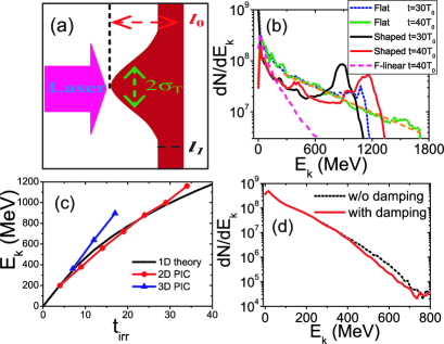
Where indicates the intensity of laser electric filed, and are the target initial density and thickness, respectively. It shows that the energy spread of accelerated ions depends on the transverse variation of the local ratio of laser intensity to the target area density. The distance the ions pass in the target is: . An initially flat target is inevitably deformed, if the laser intensity is not uniform transversely. The target deformation quickly destroys the acceleration structure and deteriorates the beam quality. From Eq. 2 we see that a target can be kept flat if its areal density is shaped properly. For the usual transversely Gaussian pulse, one can use a target with the Gaussian thickness distribution as shown in Fig. 1(a). In the following simulations, the distribution of the target thickness along the transverse direction is:
| (3) |
Here is the transverse distance to the laser axis, are the shape factors, which are shown in Fig. 1(a).
First, we use 2D simulations to find the optimal parameter region because they are computationally less expensive than simulations in the full 3D geometry. The total simulation box is , here is the laser wavelength. The foil plasma consists of two species: electrons and protons. They are initially located in the region with the density of , where is the critical density for the laser pulse with the frequency . For 1m laser pulse it is . Here, we present the results for a shaped foil target whose parameters are . For the flat target, we just set , other parameters are the same. Thus, the total number of ions in the center part of the SFT is originally less than that in the case of the flat target. The target is shaped along the Y direction in the 2D case and in the radial direction in the 3D case. The normalized maximum amplitude of the laser electric field at the focus is . This corresponds to the laser intensity of for the assumed wavelength . The full width half maximum (FWHM) radius of the focal spot is . The laser pulse has a trapezoidal temporal intensity profile (linear growth - plateau - linear decrease), with . Thus, the total laser pulse energy is about 824J. At the laser pulse enters the simulation box from the left boundary. Since the normalized laser electric field we used here is about 100 and the laser pulse is circularly polarized, we include the electron radiation damping in the VLPL code and check its effects on the electron cooling Pukhov-vlpl ; kiselev-synchrotron .
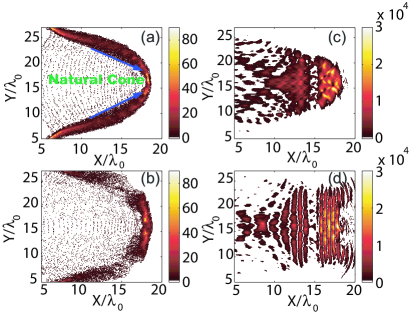
Fig. 1(b) shows the energy spectrum of the accelerated ions at and for the flat and shaped targets in the 2D-PIC simulations. The flat target produces no obvious peak structure in the spectrum. Instead, the spectrum shows an exponential decrease like with MeV for and a cutoff energy 1.7 GeV at .
When a SFT is used with the transverse shape factor , the spectrum becomes quasi-monoenergetic. The energy of the peak is about 880MeV at and later reaches 1.2GeV at , which are very closed to the analytical values obtained by solving Eq. 2. The analytical values are shown in Fig. 1(c) by the solid line. As we can see the maximum ion energy at in 2D simulation is a bit higher than the 1D theoretical value. This is because of reduction of the target area density during the interaction. Although the maximum cutoff energy of the ions in the SFT case is lower than that in the flat target case, much more protons are accelerated in a much narrower region, which benefits the further application of the accelerated proton beams.
To show the polarization effect, a linearly polarized laser pulse is used. The magenta dashed line in Fig. 1(b) shows the ion energy spectrum at . In this case, the electrons are easily heated and scattered by the oscillating part of the laser ponderomotive force. The target becomes transparent to the pulse very soon. Ions are only accelerated by the spatially dispersed electron cloud and cannot get as high energy as in the CP pulse case. The spectrum is again exponential with a lower cutoff.
Figures 2(a,b) show the spatial distribution of ions at in the two compared simulations. The target shaping leads to a more transversely uniform ion acceleration. The initially flat target in contrary is deformed and a natural cone builds up during the interaction. The laser intensity distribution shown in Fig. 2(c,d) confirms this. The natural cone focuses the lateral laser energy to the center and thus reinforces the on-axis ion acceleration. On one hand, this effects destroys the foil, but on the other hand it leads to the higher cutoff energy as shown in Fig. 1(b). Besides this, when the laser pulse irradiates the cone, electrons are easily extracted by the laser field out from the inner wall of the cone and heated because of the oblique incidence. These heated electrons disperse in space and pollute the acceleration structure, which destroys the mono-energetic character of the ion spectrum. By use of the shaped target, these undesirable effects are reduced dramatically.
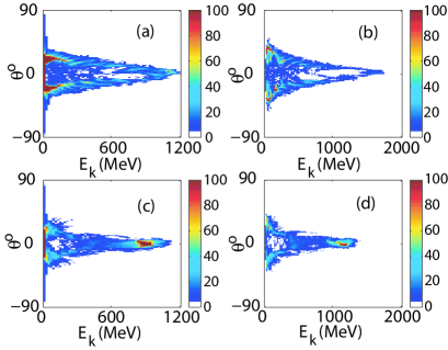
The angular distributions of the accelerated ions in the two target cases are presented in Fig. 3. It shows that in the SFT case the accelerated ions mainly move forward. However, in the flat target case, only a small portion of the highly energetic ions moves forward. Ions in the middle energy range get a considerable transverse momentum. From the simulation, we find the average emission angle for the ions whose energy is larger than 1 GeV is about in the SFT case and in the flat target case. The number of ions in this energy range is 1.9 times larger in the SFT case as compared with the flat target. Clearly, both the collimation and the total flux of accelerated ions are improved in the SFT case.
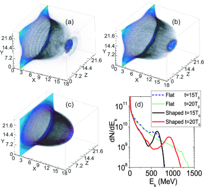
To ensure that these effects are not a 2D artefact, we perform full 3D simulations. For the shaped target, we use in the 3D-simulation. This value appears to be the optimal one for the assumed laser parameters. The initial position of the target is moved to to reduce the computational cost. The laser longitudinal profile is also reduced to be :. Other parameters are the same as those in the 2D simulation above. The electron and ion distributions at are shown in Fig. 4. As we see, in the SFT case a compact target sheath breaks out from the rest of the foil and is accelerated by the laser pulse. The same effect was also observed in the 2D simulation as shown in Fig. 2(b). In contrast, in the flat target case, Fig. 4(c) displays a continuously dispersing ion density distribution. The ion energy spectrum shown in Fig. 4(d) also confirms the quasi-monoenergetic peak in the SFT case. The number of the ions with energy larger than 800MeV are and for the flat target and shaped target, respectively. And their energies are MeV and MeV, the conversion efficiencies are and , respectively. It deserves to note that in the 3D case the simulation results are far larger than the 1D analytical values as shown in Fig. 1(c). The calculated peak value of the ions is 635MeV at , however, the simulation result is 910MeV. This larger difference is also due to the target dispersion, which is stronger in the 3D case. Generally the 1D estimation gives a higher energy conversion efficiency and a lower peak energy.
We also change the parameters and to see their effects on the final spectrum. If we fix other parameters and vary but keep , the mono-energetic part of the final spectrum almost does not change, only the lower energy part increases with . This means that only the ions in the center part of the target contribute to the final mono-energetic peak. Correspondingly, the target width is a critical parameter for the final spectrum. We find in the 2D geometry that when , the optimum spectrum appears. For the present simulation, when the monoenergetic peak exists. In the 3D geometry, the optimum value of is usually smaller than that in the 2D case. Detailed analysis and simulation work on the target shape parameters such as is still continuing.
Further, we perform simulations to check the radiation damping effects, which was found to be very important for transparent nano targets Kulagin2007 . In our simulation parameter region (, and ), , which satisfies the optimum matching of target thickness and laser intensity Tripathi2009 , the target is not transparent to the laser pulse and electrons are not completely exposed to the laser field. Most of the electrons are inside the target with relatively low transverse momenta. Our simulations show that only the highest energy electrons are cooled down as shown in Fig. 1(d). The x-ray photons are mainly radiated at the angle of () and the average photon energy is about 10keV. We find that in the present case 21mJ energy is transferred to the x-ray photons. For the ion acceleration, the very high energy electrons are not so important, only the bulk of the ponderomotive energy electrons constructs the local charge separation field. So in the present case the radiation cooling effects are not strong enough to benefit ion acceleration. Our simulation results also demonstrate there is no observable improving on the final ion spectrum when the radiation damping is considered.
In addition, we should point out that the target shaping only helps to suppress the target deformation and electron heating. The surface instabilities still exist. As we can see from Fig. 2(b) and Fig. 4(c), plasma bunches have been formed in the plasma front due to these instabilities. They make a little peak in the ion spectrum in the earlier periods. However, they evolve further if the laser pulse is long enough and make electron heating. Suppression of such kinds of instabilities should be an important work both for the laser ion acceleration itself and for the fast ignition of inertial fusion targets based on laser-accelerated ion beams fusion .
In conclusion, by target shaping we have improved both the maximum peak energy and collimation of the accelerated ions. The shaped target suppresses the target deformation, electron heating and makes the ion acceleration much more uniform in the transverse direction as compared with the plain flat target. Because of the absence of laser focusing by the natural cone, the maximum cutoff ion energy is smaller in the shaped target case. However, more ions are concentrated in the quasi-monoenergetic peak. Radiation cooling effects are checked and they are not so important in the present laser-plasma configuration.
This work is supported by the DFG programs TR18 and GRK1203. MC acknowledges support by the Alexander von Humboldt Foundation. ZMS is supported in part by the National Nature Science Foundation of China (Grants No. 10674175, 60621063) and the National Basic Research Program of China (Grant No. 2007CB815100).
References
- (1) A. Pukhov, Phys. Rev. Lett. 86, 3562 (2001); B.M. Hegelich, et al., Phys. Rev. Lett. 89, 085002 (2002); T. Esirkepov, et al., Phys. Rev. Lett. 89, 175003 (2002); J. Fuchs, et al., Nature Phys. 2, 48 (2006); B.M. Hegelich, et al., Nature (London) 439, 441 (2006); Y. Lin, et al., Phys. Plasmas, 14, 056706 (2007).
- (2) J. Denavit, Phys. Rev. Lett. 69, 3052 (1992); L. O. Silva, et al., Phys. Rev. Lett. 92, 015002 (2004); M. Chen, et al., Phys. Plasmas 14, 053102 (2007); M. Chen, et al., Phys. Plasmas 14, 113106 (2007).
- (3) T. Esirkepov, et al., Phys. Rev. Lett. 92, 175003 (2004).
- (4) T. Ditmire, et al., Nature, 386, 54 (1997).
- (5) E. Fourkal, et al., Med. Phys. 34, 577 (2007).
- (6) M. Borghesi, et al., Phys. Plasmas 9, 2214 (2002).
- (7) N. Naumova, et al., Phys. Rev. Lett. 102, 025002 (2009); M. Roth et al., Phys. Rev. Lett. 86, 436 (2001);
- (8) A. P. L. Robinson, et al., New J. Phys. 10, 013021 (2008).
- (9) O. Klimo, et al., Phys. Rev. Special Topics - Accelerators and Beams 11, 031301 (2008).
- (10) X.Q. Yan, et al., Phys. Rev. Lett. 100, 135003 (2008).
- (11) X. Zhang, et al., Phys. Plasmas 14, 123108 (2007).
- (12) A. Macchi, et al., Phys. Rev. Lett. 94, 165003 (2005).
- (13) F. Pegoraro, et al., Phys. Rev. Lett. 99, 065002 (2007).
- (14) M. Chen, et al., Phys. Plasmas 15, 113103 (2008).
- (15) S.V. Bulanov, et al., Plasma Phys. Rep. 28, 453 (2002).
- (16) T. Okada et al., Phys. Rev. E 74, 026401 (2006)
- (17) A.P.L Robinson, et al., Phys. Rev. E. 75, 015401(R), (2007); R. Sonobe et al., Phys. Plasma. 12, 073104 (2005).
- (18) H. Schwoerer, et al., Nature 439, 445 (2006).
- (19) A. Pukhov, J. Plasma Phys. 61, 425 (1999).
- (20) S. Kiselev et al., Phys. Rev. Lett. 93, 135004 (2004).
- (21) V.V. Kulagin, et al., Phys. Rev. Lett. 99, 124801 (2007).
- (22) V.K. Tripathi, et al., Plasmas Phys. Control. Fusion 51, 024014 (2009)