Composite metamaterials with dual-band magnetic resonances in the terahertz frequency regime
Abstract
Composite metamaterials(CMMs) combining a subwavelength metallic hole array (i.e. one-layer fishnet structure) and an array of split-ring resonators(SRRs) on the same board are fabricated with gold films on silicon wafer. Transmission measurements of the CMMs in the terahertz range have been performed. Dual-band magnetic resonances, namely, a LC resonance at 4.40 THz and an additional magnetic resonance at 8.64 THz originating from the antiparallel current in wire pairs in the CMMs are observed when the electrical field polarization of the incident light is parallel to the gap of the component SRR. The numerical simulations agree well with the experimental results and further clarify the nature of the dual-band magnetic resonances.
pacs:
78.20.Ci, 42.25.Bs, 41.20.Jb1 Introduction
Over the decades, the desire to manipulate the state of the electromagnetic wave propagation has been attractive to researchers in a variety of fields such as optics and chemistry [1, 2]. Metamaterials, the artificial materials with subwavelength structures, could exhibit some unusual properties which are critical for a number of potential applications such as negative refraction, superlens and electromagnetic cloak [3, 4, 5]. The first negative index metamaterials(NIMs) were demonstrated in the microwave frequency by Smith et al. [6], who designed a composite structure consisting of Pendry’s metal wires and double split-ring resonators(SRRs) [7, 8]. Subsequently, negative effective permeability has been achieved at terahertz and infrared frequencies via SRRs with reduced sizes [9, 10, 11]. Meanwhile, to hurdle the large metal losses at higher frequencies and the difficulty of experimental fabrication [12], alternative designs are introduced, showing that pairs of metal wires or metal plates, as well as multilayer fishnet structures can provide magnetic resonance at infrared and even visible frequencies [13, 14, 15, 16]. All the NIMs mentioned above exhibit the negative index behavior only at a single band. It has been proposed by D.H. Kwon et al. that dual-band negative index property can be realized in composite metamaterials (CMMs) with two periodic substructures [17].They reported the first numerical validation of dual-band NIM performance at two separated frequency bands under the same polarization in the near-infrared region. Also, C. Yan et al. investigated two electromagnetic resonance phenomena in the microwave regime with numerical simulations [18]. In this paper, by embedding the SRRs within the dielectric holes (which are air in our experiment) of the fishnet structure, we obtain dual-band magnetic resonances in the terahertz range for a linearly polarized light. Our results may be extended to other frequencies and have some potential applications in designing novel metamaterials.
2 Sample preparation
Shown in Fig.1(c),(d) are the schematic view of one unit cell and the the scanning electron microscope (SEM) image of the designed CMM (sample C) comprising SRRs embedded in holes of a perforated Au film. For comparison, a metal film perforated with a periodic array of subwavelength square holes(sample A, schematic in Fig.1(a)), and a quadratic array of SRRs (sample B, schematic in Fig.1(b))are also prepared. The lattice constants (l) of Sample A, B, C are all 14 m. The side length of a square hole for the fishnet is 11 m and the length of an arm (d) in SRR is 7 m. The dimensions of the square holes and SRRs embedded in them for sample C are the same as those of sample A and sample B.
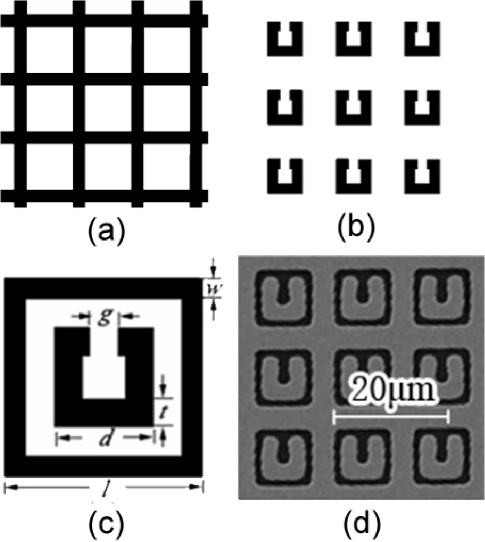
These samples were fabricated with gold films of 300nm thick deposited on silicon substrates and patterned with ultraviolet photography. To improve the adhesion between the gold film and the silicon substrate, a thin layer of 5 nm tantalum(Ta) was first deposited on the surface of the Si wafer. Each array used for the experiment here has an area of 77 mm2.
3 Spectroscopic measurements and numerical analysis
We acquired the normal-incidence transmittance spectra of the samples from 2 to 12 THz with an ABB Bomem DA8 Fourier transform infrared spectrometer. Horizontal and vertical polarizations of light were used for the measurements. In horizontal polarization the electric field of the incident light is parallel to the featuring gap of the SRR, while in vertical polarization it is perpendicular to the SRR gap.
The normal-incidence transmission spectra of sample A, B, and C with horizontal and vertical polarization are shown in Fig.2 (a) and (c) respectively. Using a commercial software CST Microwave Studio we numerically investigated the transmission of one unit cell of these arrays. Considering the overall shape and the positions of peaks and dips, the simulations are in good agreement with the experimental data, as shown in Fig. 2(b) and (d).
For sample A, the peaks at frequencies of 6.17 THz and 8.85 THz are attributed to the enhanced transmission assisted by surface plasmon polaritons of Si(1,0) and Si(1,1) at the metal and silicon interfaces [19]. These experimental results agree excellently with what the momentum matching condition indicates [20]: ksp=k0 iGx jGy, where ksp is the wave vector of SPPs, k0 is the component of the incident wave vector in the metallic film plane, and Gx and Gy are the reciprocal vectors of the fishnet array. The integers, i and j, are used to designate the resonant peaks.
The dip at 4.40 THz at the curve of sample B in Fig.2 (a) suggests the LC resonance that arises from a circulating current in the coil induced by the external horizontally polarized electric field. This magnetic resonance vanishes for the vertical polarization, leaving behind only the Mie resonance of the SRR around 6.51 THz frequency in Fig.2 (c). Also, the weak dip at 8.92 THz in Fig.2 (a) originates from Mie resonance, which is due to the depolarization field of the short axis, i.e., the width of the SRR arms [10].

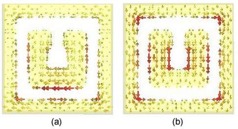
The spectra of sample C obviously inherit some characteristics of sample A and B. The reduced average transmission of Sample C in the low frequency is expected as a result of the existence of the forbidden transmission band in the long wavelength region of sample A. Besides, The location of the LC resonance for the horizontal polarization does not change, compared to that of sample B. The calculated field distribution (not shown here) for horizontal polarization suggests that the electronic excitation still localizes at the SRR’s featuring gap. The dip at 8.64 THz of sample C, however, is attributed to the magnetic resonance excitation induced by the horizontally polarized electric field, though its position is close to the Mie resonance of SRRs in sample B at 8.92 THz as shown in Fig.2(a). This can be verified in the calculated current density distribution in Fig.3 (a). The charge accumulation is opposite at the corresponding ends of the SRR bottom edge and the nearby wire of fishnet. Therefore, the antiparallel electric current in the two wires could excite magnetic field normal to the CMM plane. It is also interesting to find that the resonant wavelength (34.7 m) is approximately twice the effective optical length of the horizontal SRR arm: 2d*nsi, where d*5 m and nsi=3.42 is the refractive index of the silicon substrate [21].
A further study strengthens the above interpretation. It is noticed that at vertical polarization a dip emerges at 8.59 THz for sample C, which vanishes in sample B where there are SRRs alone, as shown in Fig.2(c). We find that its position is almost the same as the 8.64 THz dip for sample C at horizontal polarization. Actually, they both have the same physical origin. The 8.59 THz dip for sample C at vertical E-field polarization arises from the magnetic resonance of parallel metallic wires with antiparallel electric current. In this configuration, the wire pairs are the SRR arms and their neighboring fishnet wires. The induced current density distribution shown in Fig. 3(b) definitely characterizes such features: the charge accumulation oscillates in anti-phase at the SRR arms and the neighboring fishnet wires, and thus induces the antiparallel current which results in a magnetic field normal to the CMM surface.
To further confirm the above findings, we fabricated sample D, which has the same building blocks as sample C but with different dimensions. The SRRs in sample D remain the same size as that in sample C, but the lattice constant is enlarged to 22 m, and the side length of holes becomes 17 m. For comparison, we put the measured spectra of samples C and D together as shown in Fig.4, where (a) and (b) present the corresponding normal-incidence transmission spectra for horizontal and vertical polarization respectively. In both pictures, the thick solid lines are the experimental results of sample D, and the thin solid lines represent spectra of sample C. It is shown that the spectra of samples C and D have similar configuration. With numerical simulations, we could verify the nature of the dips in the spectra of sample D, which have the same origin as those in sample C. The slight red shift of the spectrum of sample D with respect to that of sample C probably results from the weaker coupling between the SRRs and the neighboring wires of the fishnet in sample D, since the distances between SRRs and the neighboring wires of the fishnet structure are larger in sample D than those in sample C.

4 Conclusions
In summary, composite metamaterials with SRRs embedded within the holes of one-layer fishnet structure are fabricated. Experimental and numerical studies indicate that there are dual-band magnetic resonaces induced by external electric field in the CMMs for the normal-incidence light. Dual-band negative permeability could occur for such CMMs when the incident waves propagate parallel to the sample surface. However, the large dielectric constant of silicon makes it difficult to extract the accurate electromagnetic parameters in the terahertz region [22]. Further research about this topic is expected to bring about potential application in in designing novel negative index metamaterials and thus in the engineering of controlling the light propagation properties.
5 Acknowledgement
The authors thank Z.Y. Li for beneficial advice and discussion, and J.J. Li for technical help. This work is supported by National Science Foundation of China (No.10674168), the MOST of China(973 project No. 2006CB601006).
References
References
- [1] Shelby R A, Smith D R, and Schultz S, 2001 Science 292, 77.
- [2] Prodan E, Radloff C, Halas N J, Nordlander P, 2003 Science, 302, 17.
- [3] Smith D R, Vier D C, Padilla W J, Nemat-Nasser S C, and Schultz S, 1999 Appl. Phys. Lett. 75, 1425.
- [4] Wiltshire M C K, Pendry J B, and Hajnal J V, 2006 J. Phys. Condens. Matter 18, 315.
- [5] Schurig D, Mock J J, Justice B J, Cummer S A, Pendry J B, Starr A F, and Smith D R, 2006 Science 314, 977.
- [6] Smith D R, Padilla W J, Vier D C, Nemat-Nasser S C, and Schultz S, 2000 Phys. Rev. Lett. 84, 4184.
- [7] Pendry J B, Holden A, Stewart W, and Youngs I, 1996 Phys. Rev. Lett. 76, 4773.
- [8] Pendry J B, Holden A, Robbins D D, and Stewart W, 1999 IEEE Trans. Microwave Theory Tech. 47, 2075.
- [9] Linden S, Enkrich C, Wegener M, Zhou J, Koschny Th, and Soukoulis C M, 2004 Science 306, 1351.
- [10] Enkrich C, Wegener M, Linden S, Burger S, Zschiedrich L, Schmidt F, Zhou J F, Koschny Th, and Soukoulis C M, 2005 Phys. Rev. Lett. 95, 203901.
- [11] Liu N, Guo H C, Fu L W, Kaiser S, Schweizer H and Giessen H, 2008 Nature Materials 7, 31.
- [12] Soukoulis C M, Linden S, Wegener M, 2007 Science 315, 47.
- [13] Podolskiy V A, Sarychev A K, Narimanov E E,and Shalaev V M, 2005 J. Opt. A: Pure APPl. Opt. 7, 32.
- [14] Zhang S, Fan W, Panoiu N C, Malloy K J, Osgood R M, and Brueck S R J, 2005 Phys. Rev. Lett. 95, 137404.
- [15] Valentine J, Zhang S, Zentgraf T, Ulin-Avila E, Genov D A, Bartal G, and Zhang X, 2008 Nature, 455, 376.
- [16] Dolling V, Wegener M, Soukoulis C M, and Linden S, 2007 Opt. Lett. 32, 53.
- [17] Kwon D H, Werner D H, Kildishev A V and Shalaev V M, 2007 Optics Express 15 1647.
- [18] Changchun Yan, Yiping Cui, Qiong Wang, and Chichuang Zhuo, 2008 Phys. Rev. E 77, 056604.
- [19] Fang X, Li Z Y, Long Y B,Wei H X, Liu R J, Ma J Y, Kamran M, Zhao H Y, Han X F, Zhao B R, and Qiu X G, 2007 Phys. Rev. Lett. 99, 066805.
- [20] Ebbesen T W, Lezec H J, Ghaemi H F, Thio T, and Wolff P Q, 1998 Nature 391, 667.
- [21] Gadot F, Belier B, Aassime A, Mangeney J, de Lustrac A, Lourtioz J M, 2007 Opt. Quant. Electron. 39, 273.
- [22] Yang J, Hwang J, and Timusk T, 2008 Phys. Rev. B 77, 205114.