Josephson tunnel junctions with ferromagnetic barriers
Abstract
Josephson tunnel junctions with the strong ferromagnetic alloy as the barrier material were studied. The junctions were prepared with high quality down to a thickness range of a few monolayers of Fe-Co. An oscillation length of between and -Josephson phase coupling and a very short decay length for the amplitude of the superconducting pair wave function in the Fe-Co layer were determined. The rapid damping of the pair wave function inside the Fe-Co layer is caused by the strong ferromagnetic exchange field and additional magnetic pair breaking scattering. Josephson junctions with Fe-Co barriers show a significantly increased tendency towards magnetic remanence and flux trapping for larger thicknesses .
pacs:
74.50.+r, 74.45.+c, 74.78.FK, 85.25.Cp, 74.25.Fy, 74.45.+cI Introduction
The proximity effect in thin film heterostructures combining superconducting (S) and ferromagnetic (F) layers is a topic of great current interest Buzdin (2005). For example, it was shown that the critical temperature depends on the thickness and magnetic orientation of F-layers in SF bi- or multilayers Tagirov (1998); Zdravkov et al. (2006); Westerholt et al. (2005). Another closely related phenomenon is the occurrence of so-called -coupling in SFS-type Josephson junctions (JJs). For certain thickness ranges of the ferromagnetic layer the Josephson coupling energy has a minimum for a phase difference and not for as in normal Josephson junctions. The ground state of the Josephson junction oscillates between - and -coupling with the oscillation period given by . The magnitude of the magnetic length depends on the kind of transport regime. In the clean limit, i.e., when for the electron mean free path in the ferromagnet holds, it is determined by , with the Fermi velocity , the exchange energy and Planck’s constant . In the dirty limit, i.e. if , depends on the electron diffusion constant via
For SIFS-type junctions in the dirty limit with magnetic scattering the critical current is given by Weides et al. (2006a); Vasenko et al. (2008):
| (1) |
where denotes the thickness of the non-magnetic (dead magnetic) part of F-layer and I stands for the AlOx tunnel barrier within the stack, is the resistance in the normal state. In general the decay length and the oscillation length are different. In the limit they are related by the equation Vasenko et al. (2008):
where the positive and negative sign in the denominator refers to and , respectively.
Only if the pair breaking scattering rate is small, i.e. , holds. For strong pair breaking scattering they differ and .
The experimental confirmation of coupling in SFS-type Ryazanov et al. (2001); Sellier et al. (2003); Blum et al. (2002) as
well as in SIFS-type JJs Kontos et al. (2002); Weides
et al. (2006a),
promoted an upsurge of interest in JJs with ferromagnetic barriers. This is motivated by the perspective
of applying -coupled Josephson junctions in flux qubits or digital logic circuits Ustinov and
Kaplunenko (2003).
For example, by combining a tunnel - and a metallic -JJ into one superconducting loop,
one can define a quantum mechanical superconducting two level system with
all properties required for the basic unit of quantum computational
devices, so-called qubits Yamashita et al. (2005). The physics of fractional vortices can also be studied in junctions with combined and coupling Weides
et al. (2006b).
For the superconducting layer S the elemental superconductor is nearly
exclusively used in the literature Sellier et al. (2003); Kontos et al. (2002); Oboznov et al. (2006); Weides
et al. (2006a); Vávra et al. (2006); Robinson et al. (2007).
For the F-layer either
diluted ferromagnets like Kontos et al. (2002), Oboznov et al. (2006); Weides
et al. (2006a) or SiFe Vávra et al. (2006)
or elemental 3d magnets are applied.
In diluted ferromagnetic alloys the pair breaking of the Cooper pairs
by the exchange field is weak and the oscillation length can be rather large, thus enabling for large thicknesses
a still high superconducting critical current density . This simplifies the observation
of oscillations in , which is taken as the main
experimental evidence for -coupling. The first minimum ( to ) Kontos et al. (2002); Weides
et al. (2006a)
and also the second minimum ( to ) Oboznov et al. (2006) was observed in JJs using Ni-Cu alloys.
Junctions with 3d transition metals like , and as the barrier material were studied in
Robinson et al. (2007); Blum et al. (2002); Bannykh et al. (2008).
By using strong ferromagnets as the barrier material one expects a very short oscillation period, corresponding to a thickness of
a few monolayers only. From the experimental point of view it is challenging to grow homogeneous barriers to obtain junctions with a sufficient comparability, which is crucial to observe the to -transition.
Small lateral inhomogeneities in the ferromagnetic layer would severely deteriorate the junction properties by locally inducing
phase shifts in the oscillating pair density.
The competition between the short oscillation period and the exponentional damping of the critical current density caused by the
strong pair breaking from the exchange field characterizes the shape of the -dependence. Since
the ratio determines the location of the 0--transition, one can estimate the crossover thickness
even if the crossover is not observable directly.
The alloy 0.750.25, which we chose for the F-layer, has the largest magnetic moment of about
per atom in the bulk among the 3d transition metal series. Therefore we expect a large exchange energy and correspondingly very short
coherence lengths which should be smaller than those of comparable Fe- or Ni-junctions. The
value of the exchange energy of 0.750.25 must be considered as the maximum value possible for SFS/SIFS junctions, based on 3d transition
metals. Until now the composition
0.750.25 has not been studied in the context of -junctions.
II Preparation and Experimental
The junctions were fabricated using a combination of dc-magnetron
sputtering and optical lithography, as described in detail in Ref.
Weides
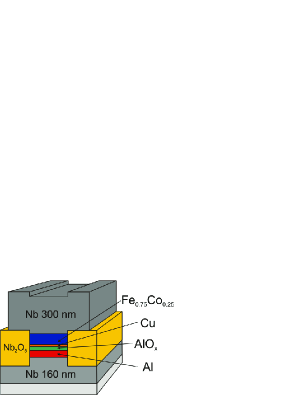
et al. (2006c). The schematic design of the junctions is depicted
in Fig.1. The complete thin film stack including the
barrier and a part of the top Nb-electrode was sputtered in one run
in a commercial sputtering chamber (Leybold Univex 450B) with a base
pressure of on a thermally oxidized -substrate
at room temperature, see Fig. 1.
After sputtering a (Nb(40 nm)Al(2.4 nm))4 multilayer, the
thick Al layer was deposited and thermally oxidized for 30 minutes
in pure oxygen at pressures of and , respectively.
By using an oxidation pressure of instead of the AlOx layer is definetely thinner and the
critical current density increases by a
factor of 12-15. This is helpfull to improve the signal quality for larger Fe-Co thicknesses, for which we expected a significant supression of the supercurrent.
The purpose of the thin Al interlayers in the Nb/Al multilayer is the optimization of the top Nb/Al interface in order to reduce the barrier rougness to a minimum.
Depending on the oxygen pressure, about of the
-layer are transformed into . The remaining metallic
film becomes superconducting by the proximity effect below the
transition temperature of . On top of the -layer a
thick non-magnetic (N) -film is sputtered, followed by the Fe-Co ferromagnetic film.
In recent work Weides
et al. (2006c) it was shown that the -interlayer is needed to keep the interface
roughness of the F-layer on an acceptable level.
The Fe-Co film is wedge shaped along the substrate length using the natural gradient of the sputtering rate. As a final step
the -counter-electrode with a thickness of was deposited.
After the lift-off process mesas of and are defined by optical lithography and ion-beam etching.
Afterwards the current leads and the sides of the stack are isolated by
anodic oxidation of Nb Kroger et al. (1981). Finally,
after a short Ar plasma etching, the top electrode is completed by
sputtering another 400 nm of Nb.
For the present study we prepared two series of junctions with two
different barrier thicknesses. The first series
with the thinner barrier covered the thickness range
for the Fe-Co layer and had a normal state
resistance for the JJs of about and 0.052
(), respectively.
The second series with a thicker barrier covered
the thickness range and had
().
The ferromagnetic properties of the thin Fe-Co layers were studied by a commercial SQUID magnetometer on identical, non-microstructured layer stacks covering the same Fe-Co thickness range. The I-V characteristics of the Josephson junctions with and without an applied magnetic field in the film plane were measured at in a shielded cryostat using home made electronics.
III Results and discussion
The magnetism of the alloy layer in the JJs plays
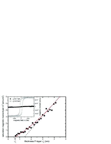
an important role, thus we first characterize the magnetic properties. The magnetic hysteresis loops of the SINFS stacks with
in the same range as for the JJs have been measured at . In the inset of
Fig.2 we show two examples
for a thickness and . For the thicker
film one observes a nearly square shaped hysteresis loop with a coercive
field of and a saturation magnetization corresponding to about
70% of the bulk value. For the thinner film there is only a very
weak ferromagnetic signal, indicating that due to intermixing at the interfaces very thin Fe-Co layers become non-magnetic.
The saturation magnetic moment normalized to the sample area is plottet versus the nominal thickness of the Fe-Co layer in Fig.2.
Below a nominal thickness of nm the layers are non ferromagnetic. Above nm the ferromagnetic moment gradually
increases and approaches the bulk moment of 2.5 /atom above about nm. This indicates that at each interface by alloying
with Nb or Cu there is a reduction of the ferromagnetic moment and the first two monolayers at each side are non ferromagnetic.
A second experimental ingredient needed for a theoretical description of the Josephson junctions is the conduction electron mean free path of the ferromagnetic layer , which defines whether the dirty limit or the clean limit theory for the JJs applies. We measured the electrical conductivity of a single thin film of thickness on thermally oxidized . The -layer was capped with 30 nm of sputtered SiO2. The film had a very small residual resistivity ratio RRR (defined as the ratio of the resistance measured at room temperature and at ) and a large residual resistivity of . For Fe-Co in Ref.Kim et al. (2006) a smaller value of was determined, indicating the sensitive influence of different growth conditions. The electron mean free path can be estimated using the standard free electron model formula Pippard (1960):
with the electronic specific heat coefficient and the Fermi velocity . With and (: , : Robinson et al. (2007)) we estimated . This very small value for the mean free path indicates strong disorder scattering from the random distribution of and -atoms in the alloy. The value for derived here must be considered as a rough estimate, because the growth on SiO2 is not directly comparable to the growth within the SINFS-stack.
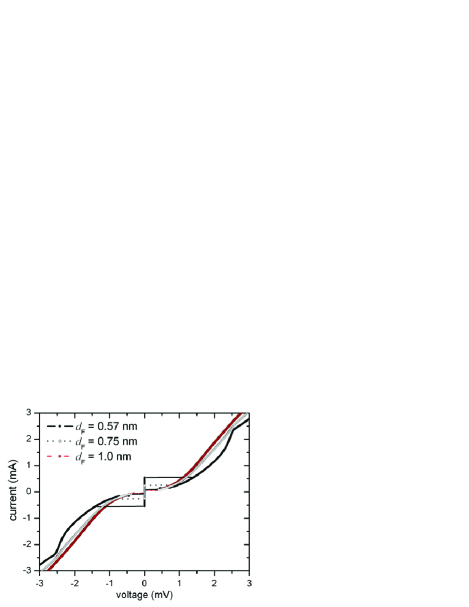
In Fig. 3 we show I-V-curves of junctions with different thicknesses of the ferromagnetic layer . One finds the typical features of Josephson tunnel junctions with ferromagnetic barriers Weides et al. (2006a, c); Kontos et al. (2002). For small thicknesses the Josephson phase is strongly underdamped and the I-V-curves exhibit a pronounced hysteresis. For the lowest thickness in Fig.3 one can resolve the double superconducting gap of at . With increasing thickness this feature and the hysteresis gradually vanish.
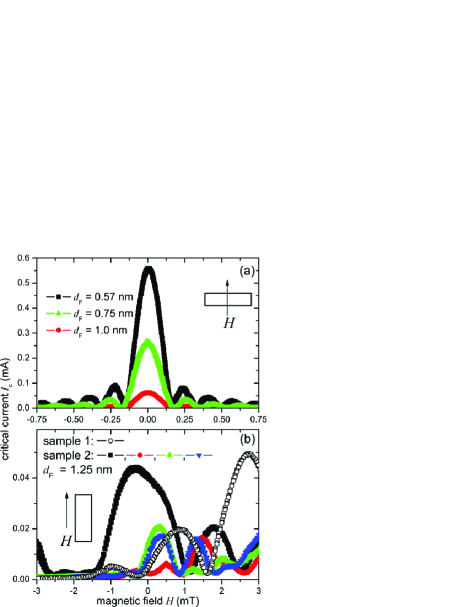
The Fraunhofer pattern of the same junctions are shown
in Fig.4a. For we observe
highly symmetric, periodic patterns with vanishing critical current
at the minima, which is a clear indication of the homogeneity of
both the and Fe-Co barriers in our samples. For thicknesses
(see Fig.4b) the global maximum of the Fraunhofer patterns
was found to be increasingly shifted towards external fields ,
indicating the existence of an intrinsic magnetic stray field. Similar observations in -based JJs have been published
recently in Ref.Weides (2008). In the case of Ni the flux trapping effects appear for thicknesses which
is significantly larger than in our samples. In the case of Fe0.75Co0.25 the magnetic stray field appears within the 0-state, whereas in the case of
Ni the samples are already in the -state.
The -curve of one sample (open circles) in Fig.4b appears to
be shifted by along the field axis, corresponding to .
In this case the external field was parallel to the long axis of the junction. If was orientated perpendicular to the long axis
only extremely small critical currents could be measured even for maximum fields around 3 mT. This indicates the presence
of a magnetic shape anisotropy within the F-layer, which shifts the Fraunhofer pattern opposite to the magnetization direction Weides (2008).
Additionally, we usually found indication of some trapped magnetic flux, probably emanating from the ferromagnetic film and frozen
in below . This flux leads to irregular, not reproducible patterns and the global maximum critical current
cannot be defined precisely. The maximum experimental
critical current which is seen in the experiment is always an underestimation for the true maximum critical current. Additionally,
this random error causes an increasing scattering of the data
points for in .
In Fig.5 the global maximum critical current determined by versus the nominal
thickness of the ferromagnetic layers is depicted. In fact the product of the critical current
and the normal state junction resistance is plotted for a better comparison of the two series of samples
with different thickness of the -barrier.
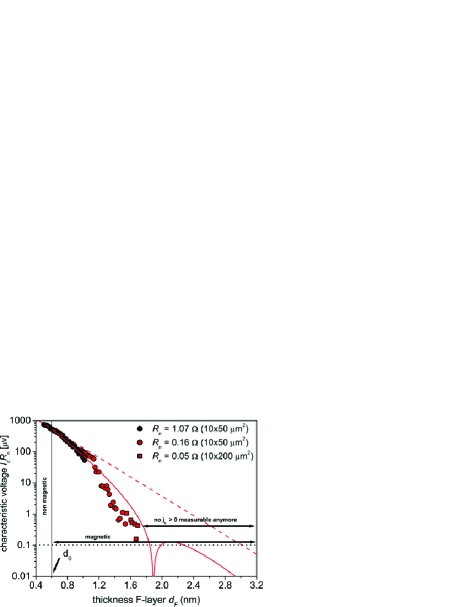
is strongly damped for increasing and reaches our experimental resolution limit
of beyond .
For a quantitative analysis of )
we divided the data into two sections, as done in case of -based SIFS junctions in Ref. Bannykh et al., 2008.
For the JJs are approximately treated as a SINS-type junction, with
meV. Then Eq.1 converts into:
| (2) |
with the damping length
| (3) |
and the diffusion constant in the non-ferromagnetic layer (see Ref.Vasenko et al. (2008)). From the tangent at very thin Fe-Co layers () (see Fig.5, dashed line) we derive a very short damping length and , corresponding to a magnetic scattering energy of and a critical current density of the SINS stack of . This indicates a decrease of by a factor of 2 caused by the F-layer interface scattering compared to SIS or SINFS JJs. In the case of SIFS JJs with the magnetically weaker as interlayer, a decrease by factor of was determined Bannykh et al. (2008).
In the thickness range nm the ferromagnetism sets in (see Fig.4) and the theory for SIFS junctions applies. From the envelope of the function following Eq.1, which was applied to our data points in the thickness range between , we can estimate the damping length (see Fig.5). Obviously, the damping in the magnetic part of the film is stronger than in the non-magnetic part (). This indicates the effect of the strong exchange interaction on the pair density.
For a quantitative comparison with theory the model for SIFS junctions can be adapted to our system by considering the IN-layers between Nb and Fe-Co as one interface with a very low transparency. In this model the oscillation length is definitely larger then the decay length , indicating a considerable influence of pair breaking scattering on the tunneling. Using the experimental value for , and we calculate and . The ratio is slightly larger but has the same magnitude as the corresponding value of where has been determined Oboznov et al. (2006). Obviously the scattering energy of the -alloy is 7.5 times smaller than the one for Fe-Co. The value obtained for the exchange energy is found to be significantly larger than for the elemental magnets (), () or () Robinson et al. (2007). This seems reasonable considering the strong magnetic properties of Fe0.75Co0.25.
It should be mentioned, that although the 0 to -transition is located below the instrumental resolution limit of , the thickness dependence in Fig.5 suggests a crossover at nm. The experimental curve cannot be fitted reasonably by a pure exponentional decay, a fit with Eq.1 is much better. The calculated oscillation period fits perfectly into the series of values obtained for other systems like Bannykh et al. (2008) for pure Ni and Oboznov et al. (2006) for the Ni0.53Cu0.47 alloy.
IV Summary and conclusions
We have shown that high quality JJs with the strong
ferromagnetic alloy Fe-Co as the barrier layer can be grown. The high
quality of the barriers has been demonstrated by the observation of
excellent Fraunhofer patterns in case of non-magnetic or magnetically weak,
i.e. very thin F-layers. The JJs are
characterized by a strong damping of the superconducting pair amplitude
in the Fe-Co layers and a small oscillation period for the transition
between 0-coupling and coupling. The strong damping of the
pair amplitude even for the thickness range below ,
where the Fe-Co layers appear to be non-ferromagnetic in the hysteresis loops,
is probably caused by pair breaking scattering on magnetic fluctuations,
which exist in itinerant ferromagnets close to a ferromagnetic phase
boundary. The ferromagnetic range, too, is characterized by strong
inelastic pair breaking scattering of the Cooper pairs, indicating
a high density of states for low energy magnetic excitations in the
Fe-Co ferromagnetic layer with a thickness of only a few monolayers.
Additionally we observe non-reproducible flux trapping
and intrinsic magnetization effects.
Applying the dirty limit model to our data gives a reasonable set of parameters and a consistent picture of our system.
Although the 0 to -transition of the JJ was not directly observable due
to the strong damping of the critical current density we could estimate its position at .
Acknowledgement
The authors thank R. Waser, G. Pickartz and R. Borowski for support. D. S., K. W. and H. Z. acknowledge financial support by SFB-491, and M. W. by project WE 4359/1-1.
References
- Buzdin (2005) A. I. Buzdin, Rev. Mod. Phys. 77, 935 (2005).
- Tagirov (1998) L. R. Tagirov, Physica C 307, 145 (1998).
- Zdravkov et al. (2006) V. Zdravkov, A. Sidorenko, G. Obermeier, S. Gsell, M. Schreck, C. Müller, S. Horn, R. Tidecks, and L. R. Tagirov, Phys. Rev. Lett. 97, 057004 (2006).
- Westerholt et al. (2005) K. Westerholt, D. Sprungmann, H. Zabel, R. Brucas, B. Hjörvarsson, D. A. Tikhonov, and I. A. Garifullin, Physical Review Letters 95, 097003 (2005).
- Weides et al. (2006a) M. Weides, M. Kemmler, E. Goldobin, D. Koelle, R. Kleiner, H. Kohlstedt, and A. Buzdin, Appl. Phys. Lett. 89, 122511 (2006a).
- Vasenko et al. (2008) A. S. Vasenko, A. A. Golubov, M. Y. Kupriyanov, and M. Weides, Phys. Rev. B 77, 134507 (2008).
- Ryazanov et al. (2001) V. V. Ryazanov, V. A. Oboznov, A. Y. Rusanov, A. V. Veretennikov, A. A. Golubov, and J. Aarts, Phys. Rev. Lett. 86, 2427 (2001).
- Sellier et al. (2003) H. Sellier, C. Baraduc, F. Lefloch, and R. Calemczuk, Phys. Rev. B 68, 054531 (2003).
- Blum et al. (2002) Y. Blum, A. Tsukernik, M. Karpovski, and A. Palevski, Phys. Rev. Lett. 89, 187004 (2002).
- Kontos et al. (2002) T. Kontos, M. Aprili, J. Lesueur, F.Genet, B. Stephanidis, and R. Boursier, Phys. Rev. Lett. 89, 137007 (2002).
- Ustinov and Kaplunenko (2003) A. V. Ustinov and V. K. Kaplunenko, J. Appl. Phys. 94, 5405 (2003).
- Yamashita et al. (2005) T. Yamashita, K. Tanikawa, S. Takahashi, and S. Maekawa, Phys. Rev. Lett. 95, 097001 (2005).
- Weides et al. (2006b) M. Weides, M. Kemmler, E. Goldobin, H. Kohlstedt, R. Waser, D. Koelle, and R. Kleiner, Phys. Rev. Lett. 97, 247001 (2006b).
- Oboznov et al. (2006) V. A. Oboznov, V. V. Bol’ginov, A. K. Feofanov, V. V. Ryazanov, and A. I. Buzdin, Phys. Rev. Lett. 96, 197003 (2006).
- Vávra et al. (2006) O. Vávra, S. Gaži, D. S. Golubović, I. Vávra, J. Dérer, J. Verbeeck, G. V. Tendeloo, and V. V. Moshchalkov, Phys. Rev. B 74, 020502 (2006).
- Robinson et al. (2007) J. W. A. Robinson, S. Piano, G. Burnell, C. Bell, and M. G. Blamire, Phys. Rev. B 76, 94522 (2007).
- Bannykh et al. (2008) A. A. Bannykh, J. Pfeiffer, V. S. Stolyarov, I. E. Batov, V. V. Ryazanov, and M. Weides (2008), http://arxiv.org/abs/0808.3332.
- Weides et al. (2006c) M. Weides, K. Tillmann, and H. Kohlstedt, Physica C 437-438, 349 (2006c).
- Kroger et al. (1981) H. Kroger, L. N. Smith, and D. W. Jillie, Appl. Phys. Lett. 39, 280 (1981).
- Pippard (1960) A. B. Pippard, Rep. Prog. Phys. 23, 176 (1960).
- Kim et al. (2006) K. Kim, J. H. Kwon, J. Kim, K. Char, H. Doh, and H.-Y. Choi, Phys. Rev. B 74, (2006).
- Kim et al. (2005) J. Kim, J. H. Kwon, K. Char, H. Doh, and H. Y. Choi, Phys. Rev. B 72, 14518 (2005).
- Weides (2008) M. Weides, Appl. Phys. Lett. 93, 52502 (2008).