Acoustic cloaking and imaging using complementary media
Abstract
Base on the concept of complementary media, a scheme to achieve cloak an object outside the shell is proposed by Yun lai et al [PRL 102, 093901].We generalize the concept in acoustic waves and demonstrate numerically how to achieve the acoustic cloaking and imaging with complementary media.
pacs:
43.20.FnMaking use of form-invariant coordinate transformation of Maxwell’s equation, J. B. Pendry and Leonhardt independently proposed the invisibility cloak and the concept of transformation media for electromagnetic (EM) waves 1 ; 2 . Transformation media transport electromagnetic (EM) waves without reflection, giving rise to exotic EM devices such as wave concentrator3 , cylindrical superlens4 , etc., besides invisibility cloak5 ; 6 ; 7 ; 8 ; 9 . From the view of transformation optics, left-handed materials are precisely the complementary media of conventional dielectric materials by mirror transformation10 ; 11 ; 12 ; 13 . Under appropriate design, a complementary object destructively interferes with an outside object, and perfectly cancels the scattered waves from it, giving rise to perfect cloak to the whole system14 . The idea is also successfully applied to design perfect lens15 , the “superscatterer”16 and the “anticloak”17 ; 18 as well. The concept of transformation media can be extended to the scope of acoustic waves. A scheme to achieve acoustic cloaking in two dimensions was proposed by Cummer and Schurig19 . Subsequently, Huanyang Chen and C. T. Chan generalized the idea to three dimensions by mapping the acoustic equation directly to the conductivity equation20 . Recently, a technique to achieve broadband acoustic cloak was proposed by J. B. Pendry and Jensen Li21 .
In this paper, we show that the concept of complementary media can be generalized in acoustic waves. The acoustic complementary media possess constitute parameters in opposite sigh of each other. Perfect acoustic cloaking and perfect imaging with complementary media are demonstrated numerically in two dimensions. The recovery of the acoustic wave field by complementary media is interpreted in one dimensional multilayer system.
The acoustic wave equation takes a form as:
| (1) |
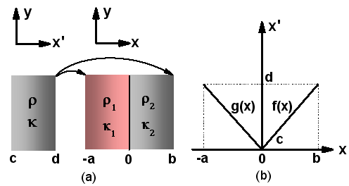
where mass density and bulk modulus are two constitutive parameters of the acoustic media at point. An alternative parameter equivalent to is sound velocity with We will use and instead to characterize acoustic media later in full-wave simulations. Concerning the acoustic complementary media, we start from a layered model by transforming a single layer in acoustic wave space into two layers with mapping functions15 . As shown in Fig.1, the original region in the Cartesian coordinate of acoustic virtual space with now is transformed into two regions and in real space by mapping function in Fig. 1(b). For simplicity, we adopt a linear form of mapping function with in the region of , and in the region of . The boundary continuum conditions of acoustic waves requires and to satisfy with and at the three interfaces , and . We obtain the constitutive parameters of the two transformed layers 1 and 2 by the following equations:
| (2) |
| (3) |
Where, and “” denotes the determinant of matrix.
With the mapping functions satisfy to , layer 1 and layer 2 make up of acoustic complementary media. And we have and for the mass density and bulk modulus of the two layers, where and are the constitutive parameters of the original layer. The transformation assigns exactly the same amplitude and phase to acoustic pressure field at the boundary and at as if the two layers do not exist.
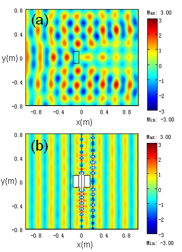
We now numerically demonstrate how to realize two-dimensional acoustic cloak with complementary media. Using a finite element solver (COMSOL Mutiphysics), we calculate the acoustic scattering from a sized rectangle object incident from left to right by a monochromatic plane wave at frequency . The host media is air. The mass density and the sound velocity of the object are and respectively, Fig. 2(a) presents the normalized pressure fields in colormap with respect to the incidence. In Fig. 2(b), the host media and are air, the right region is “anti-air” with parameters and . The object, embedded in the air layer to be cloaked, is exactly the same as that in Fig. 2(a). An “anti-object”, with the same size and shape of the object at the left side, is embedded in the “anti-air” layer. The object and the “anti-object” are symmetrically positioned with respect to axis. The normalized acoustic pressure fields are shown in Fig. 2. The regions where the normalized amplitude of the pressure fields exceeds the bound of the color bar are marked by white color. The absence of the scattered waves indicates invisibility of the object and the anti-object.
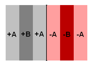
To understand the perfect acoustic cloaking by complementary media in Fig. 2(b), we consider a one-dimensional layered system comprised of complementary media. As shown in Fig. 3, the whole structure is the combination of two trilayers and . Layer and layer possess the same thickness , layer and layer possess the same thickness . The constitutive parameters of the layers and their anti-layers satisfy with and respectively. According to one-dimensional transfer matrix method theory22 a centrosymmetric trilayer can be equivalent to one homogeneous layer with effective characteristic impedance and phase thickness . The scheme also applies for the trilayer , its characteristic impedance and phase thickness satisfy with and . The characteristic matrix of an acoustic layer has a similar form of that of transverse magnetic (TM) polarization in EM waves, so that we derive the characteristic matrix of the whole structure as:
| (4) |
The fact that regresses to an identity matrix means that the complementary tri-layer as an anti-object rehabilitates the whole wave field by canceling the scattering waves completely as if the whole system were nothing but the host media.
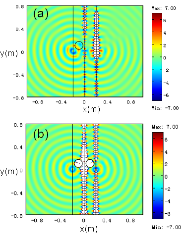
We also use the concept of complementary media to demonstrate the imaging effect in acoustic waves. As a specific example, in Fig. 4(a) we show the pressure field distribution when a point source interacting with complementary media and a cylinder object. A point source with frequency is placed at the position of the left boundary of a bilayer, in which the left one is an air layer at with , , and the right one is an “anti-air” layer at with , . A cylinder object with a radius of and , , is located at in the left air layer. As shown in Fig. 4(a), we can’t get an image of the source. If we set an “anti-object” in the “anti-air” layer right side with same size and shape of the cylinder object, and ensure them symmetrically positioned to axis. Then we can get an image with good quality as illustrated in Fig. 4(b). This implies that image effect can be achieve even an obstacle is placed in front of the source.
In conclusion, we have generalized the concept of the complementary media in acoustic waves. Using this concept, we show examples to cloak an object outside and achieve perfect image in acoustic waves. Undoubtedly, this scheme can be extend to three dimensions and not constrained by the shape of the object. Recent research work on acoustic metamaterials have shown that bulk modulus and mass density can be designed to vary in a wide range from negative to positive23 ; 24 ; 25 ; 26 ; 27 ; 28 , making transformation media attainable practically in acoustic waves as well as complementary media. This work was supported by the National 863 Program of China (Grant No.2006AA03Z407), NSFC (GrantNo.10574099, No.60674778), NECT, STCSM and Shanghai Education and Development Foundation (No. 06SG24).
References
- (1) J. B. Pendry, D. Schurig, and D. R. Smith, Science 312, 1780-1782 (2006).
- (2) U.Leonhardt, Science 312, 1777 (2006).
- (3) A. D. Yaghjian, and S. Maci, New J. Phys. 10, 115022 (2008).
- (4) Min Yan, Wei Yan, and M. Qiu, Phys. Rev. B. 78, 125113 (2008).
- (5) D. Schurig, J. J. Mock, B. J. Justice, S. A. Cummer, J. B. Pendry, A. F. Starr, and D. R. Smith, Science 314, 977 (2006).
- (6) Steven A. Cummer, Bogdan-Ioan Popa, David Schurig, D. R. Smith, and J. Pendry, Phys. Rev. E 74, 036621 (2006).
- (7) Zhichao Ruan, Min Yan, Curtis W. Neff, and M. Qiu, Phys. Rev. Lett. 99, 113903 (2007).
- (8) Hongsheng Chen, Bae-Ian Wu, Baile Zhang, and J. A. Kong, Phys. Rev. Lett. 99, 063903 (2007).
- (9) W. Cai, U. K. Chettiar, A. V. Kildishev, and V. M. Shalaev, Nat.Photonics. 1, 224 (2007).
- (10) J. B. Pendry, Opt. Express 11, 755 (2003).
- (11) D. Schurig, and D. R. Smith, New J. Phys. 7, 162 (2005).
- (12) J. B.Pendry, and S. A. Ramakrishna, J. Phys.: Condens. Matter 15, 6345 (2003).
- (13) J. J. Monzon, A. G. Barriuso, and L. L. Sanchez-Soto, Eur. J. Phys. 29, 431 (2008).
- (14) Yun Lai, Huanyang Chen, Zhao-Qing Zhang, and C. T. Chan, Phys. Rev. Lett. 102, 093901 (2009).
- (15) Wei Yan, Min Yan, and M. Qiu, Phys. Rev. B 79, 161101 (2009).
- (16) Tao Yang, Huanyang Chen, Xudong Luo, and H. Ma, Opt. Express 16, 18545 (2008).
- (17) H. Chen, X. Luo, H. Ma, and a. C. T. Chan, Opt. Express 16, 14603 (2008).
- (18) Giuseppe Castaldi, Ilaria Gallina, Vincenzo Galdi, Andrea Alù and N. Engheta, Opt. Express 17, 3101 (2009).
- (19) S. A. Cummer, and D. Schurig, New J. Phys. 9, 45 (2007).
- (20) H. Chen, and C. T. Chan, Appl. Phys. Lett. 91, 183518 (2007).
- (21) J. B. Pendry, and J. Li, New Journal of Physics 10, 115032 (2008).
- (22) P. G. Luan, and Z. Ye, Phys. Rev. E 63, 066611 (2001).
- (23) Z. Y. Liu, X. X. Zhang, Y. W. Mao, Y. Y. Zhu, Z. Y. Yang, C. T.Chan, and P. Sheng, Science 289, 1734 (2000).
- (24) J. Li, and C. T. Chan, Phys. Rev. E 70, 055602(R) (2004).
- (25) N. Fang, D. J. Xi, J. Y. Xu, M. Ambati, W. Srituravanich, C. Sun, and X. Zhang, Nat. Mater. 5, 452 (2006).
- (26) Y. Cheng, J. Y. Xu, and X. J. Liu, Phys. Rev. B 77, 045134 (2008).
- (27) Z. Yang, Jun Mei, Min Yang, N. H. Chan, and P. Sheng, Phys. Rev. Lett. 101, 204301 (2008).
- (28) S. H. Lee, C. M. Park, Y. M. Seo, Z. GuoWang, and C. K. Kim, arXiv:0901.2772v2 (2009).