Striped Multiferroic Phase in Double-Exchange Model for Quarter-Doped Manganites
Abstract
The phase diagram of quarter-hole-doped perovskite manganites is investigated using the double-exchange model. An exotic striped type-II multiferroic phase, where of the nearest-neighbor spin couplings are orthogonal to each other, is found in the narrow-bandwidth region. Comparing with the spiral-spin ordering phase of undoped manganites, the multiferroic Curie temperature of the new phase is estimated to be times higher, while the ferroelectric polarization is similar in magnitude. Our study provides a path for non-collinear spin multiferroics based on electronic self-organization, different from the traditional approach based on superexchange frustration.
pacs:
75.80.+q, 75.47.Lx, 71.10.Hf, 75.30.KzIntroduction. Multiferroics, materials where ferroelectric (FE) and magnetic orders coexist, have attracted enormous interest due to their technological relevance and fundamental science challenges Fiebig:Jpd . Based on the microscopic origin of the FE polarization (), the multiferroics can be classified into two families Khomskii:Phy . Type-I multiferroics, where ferroelectricity and magnetism have different origins, are often good ferroelectrics with high FE transition temperatures and large . However, the coupling between magnetism and ferroelectricity is usually weak. In contrast, in the type-II multiferroics (magnetic multiferroics), such as MnO3 (=Tb and Dy) Kimura:Nat , the ferroelectricity is caused by, and thus it is strongly coupled with, a particular magnetic order. The pursuit for type-II multiferroics with higher critical temperatures and larger is one of the most fundamental challenges of modern condensed-matter physics Kimura:Nm .
The manganite family provides fertile ground for both type-I (e.g. BiMnO3 and hexagonal YMnO3) and type-II (e.g. MnO3 perovskites, =Tb, Dy, Ho, or Eu1-xYx) multiferroics. Recent theoretical studies predicted additional type-I multiferroics in manganites, e.g. Pr0.6Ca0.4MnO3, CaMnO3, and BaMnO3 Efremov:Nm . However, since among type-II multiferroics the manganite multiferroics show the largest (e.g. - C/m2 for TbMnO3 and DyMnO3 Kimura:Nat , C/m2 for HoMnO3 Sergienko:Prl ), it would be even more exciting if new type-II manganite multiferroics with higher could be discovered.
Although the manganite phase diagrams have been extensively studied Dagotto:Prp , exotic new phases may still be waiting to be discovered, particularly in the narrow-bandwidth limit where the multiferroic manganites are located. Therefore, it is important to continue the detailed investigation of this narrow-bandwidth regime. Along this direction, recent studies addressed the systematic phase diagram for undoped manganites using the two-orbital double-exchange (DE) model Dong:Prb08.2 .
Compared with the undoped case, the doped multiferroics, which have not been widely studied, can provide a fruitful playground since one extra degree of freedom, the charge, is now active. It is already known that doping-driven electronic self-organization can be very important to the emergence of high- superconductivity and colossal magnetoresistance Dagotto:Sci . Thus, it is natural to explore a similar path in multiferroics. For instance, very recently, the Ca-doped BiFeO3 and TbMnO3 were studied experimentally Yang:Nm ; Mufti:Prb . In this Letter, theoretical investigations are extended to the doped manganites, revealing a type-II multiferroic phase at quarter-doping that was missing in previous theoretical studies Hotta:Prl .
Model and methods. In this letter, the phase diagram of quarter-doped manganites will be studied using the two-orbital DE model. The Hamiltonian is:
| (1) |
which includes the two-orbital DE hopping term , the nearest-neighbor (NN) superexchange (SE) energy , and the lattice contribution that contains the electron-phonon coupling and lattice’s elastic energy. Details of this well-known Hamiltonian can be found in previous publications Dagotto:Prp ; Dong:Prb08.2 . The energy unit will be the DE hopping (- eV). Besides , there are two main parameters in this Hamiltonian: for the SE, and for the electron-phonon coupling.
Three numerical methods have been employed to cross check the results. The first technique is the zero temperature () variational method where the ground-state energies of several phases are compared. This calculation can be applied on both finite- and infinite-size lattices. However, a set of candidate phases must be preselected. To avoid such a possible bias, the finite- Monte Carlo (MC) simulation is also here performed, on finite-size clusters, to confirm the phase diagram obtained by the variational method. The typical clusters, with periodic boundary conditions, used here are 2-dimensional (2D) ( and ). Some hidden phases or phase-separation tendencies missed by the first method can be revealed in the MC simulation. Finally, the zero- relaxation technique is used to optimize the ground state spins’ and lattice’ patterns on a finite-size cluster. The second and third methods are only applied to 2D lattices in the current effort because they are computationally intense. The three processes are cycled several times to improve the accuracy of the phase diagram.
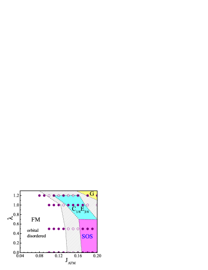
Results and Discussions. The 2D ground state phase diagram of the quarter-doped DE model is shown in Fig. 1 3D . A prominent FM metallic orbitally-disordered phase occupies the small region, in agreement with the phase diagram of large and intermediate bandwidth manganites. However, our most important result is revealed when is increased, keeping small: in this regime a new multiferroic phase (dubbed “SOS” as explained below) is found. Its existence is confirmed by all the three methods used here. In addition, the C1/4E3/4 phase, predicted by Hotta et al. Hotta:Prl , appears when 1. Finally, a G-AFM region is found when both and are large enough comment-G . Near the boundaries between these robust phases the spin patterns are difficult to identify and phase separation may exist there (shaded regions in Fig. 1) comment-A . These regions are beyond our current computational capabilities. Thus, here the emphasis will be only on the clearly identified states in the phase diagram.
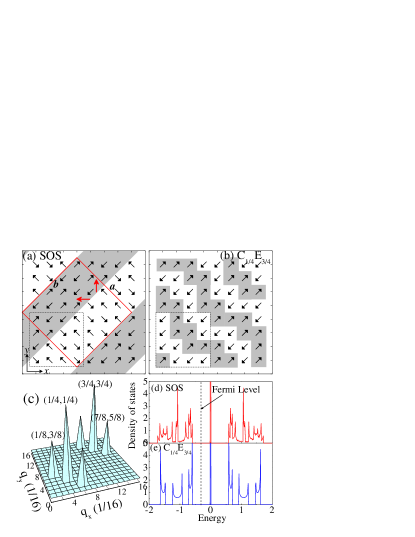
Let us now analyze the physical properties of the SOS phase, comparing properties with those of the C1/4E3/4 phase. The spin patterns of these two phases are shown in Fig. 2(a-b) (both of them are perfectly AFM along the -axis). For the SOS phase, the most prominent features are the diagonal stripes where spin domains with orthogonal orientations merge. For this reason, this phase is called “Spin-Orthogonal Stripe” (SOS). This spin pattern gives rise to a FE at the stripe boundaries via the Dzyaloshinskii-Moriya (DM) interaction (, where is the unit vector connecting the NN spins and ) Sergienko:Prb . The two types of local that appear in the SOS state are shown in Fig. 2(a). The total arises from the sum of these local , and it is perpendicular to the stripes. The local at the stripe boundaries should be larger than those in TbMnO3 and DyMnO3, since here is the largest possible in noncollinear spin orders. However, considering that only NN spins are orthogonal, then the global of the state should be similar ( C/m2) as in TbMnO3 and DyMnO3. In contrast, the C1/4E3/4 phase has all spins collinear, forming FM zig-zag chains with alternative C- and E-AFM sections comment .
Note that the spin structure factors () of the SOS and C1/4E3/4 phases are exactly the same (Fig. 2(c)) comment-same . The reason is that the spin pattern of the SOS phase can be viewed as the combination of two C1/4E3/4 patterns: by decomposing the spin vectors in Fig. 2(a) along the and axes, both the and components by themselves form the C1/4E3/4 state, with just a relative shift between the two C1/4E3/4 patterns formed by this procedure. Therefore, care must be taken in separating the SOS and C1/4E3/4 states experimentally because they are intimately connected.
It is also important to confirm that the SOS phase is an insulator, as required by ferroelectricity. The density of states on the infinite-size lattice indeed shows that both the SOS and C1/4E3/4 phases have a gap at the Fermi level (Fig. 2(d-e)). Thus, it is safe to predict that the SOS state is a type-II multiferroic.
The theoretical prediction of the SOS phase is exciting for its new mechanism for noncollinear spin ordering, which can improve the . Traditionally, noncollinear spirals are formed by the competition between the NN and next-nearest-neighbor (NNN) SEs, namely employing the SE frustration Kimura:Prb ; Dong:Prb08.2 . However, because the NNN SE is usually weak, it becomes difficult to improve based on such a frustration mechanism. Another known path for noncollinear spin order is the DM interaction Sergienko:Prb , but it is also very weak and thus can only induce small spin angles. In contrast, the spin angle in our SOS phase is not driven by the NNN exchange frustration nor the DM interaction. Instead, the noncollinear spin structure of the SOS phase is driven by the competition between DE and NN SE. While in cuprate and nickelate stripes the spins across the stripes are AFM ordered (-shifted), in manganites there are also FM tendencies caused by DE and, thus, a reasonable compromise at the stripes is to have spin angles. Since both DE and SE are NN interactions, much stronger than NNN ones, a higher SOS is expected.
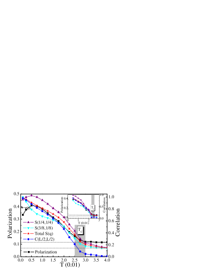
To confirm this expectation, the finite- MC results, including the FE , the spin structure factors, and the real-space spin correlation at the maximum distance, are shown in Fig. 3. All these results give a very similar , here defined as the where the magnetic correlation length is as large as the clusters studied. For the = lattice, the of the SOS phase is about -, which is - times the of the spiral state of previous investigations (, obtained using the same MC technique on a = lattice Dong:Prb08.2 ). Even for the = lattice, the SOS is about -, still much higher than in the spiral state and showing that size effects are small. Therefore, the real of the SOS phase is estimated to be K ( times the of typical spiral manganites). It is reasonable to expect the discovery of other multiferroic noncollinear phases based on this electronic self-organization mechanism with even higher ’s.
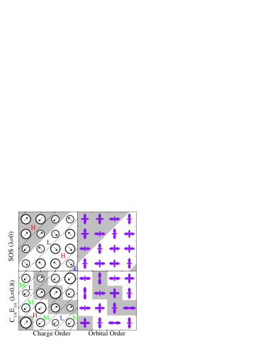
Charge/Orbital order and Coulomb interactions. Both the SOS and the C1/4E3/4 phases have a complex charge/orbital order, forming stripes along the -axis (see Fig. 4). For the SOS phase, holes accumulate at the diagonal stripe boundaries where originates. For the C1/4E3/4 phase, electrons accumulate at the E-AFM corner sites while holes accumulate at the C-AFM bridge sites Hotta:Prl , in agreement with the pure E-AFM (undoped case) and C-AFM (over half-doped cases) properties. Also, note that the charge disproportion in C1/4E3/4 is more prominent than that in the SOS phase. Thus, if the Coulomb interaction is considered, the C1/4E3/4 phase will be further suppressed in the phase diagram. Using the mean-field approximation Hotta:Prb , it can be shown that the phase boundary SOS-C1/4E3/4 can be shifted from to by incorporating the on-site Hubbard interaction. The orthorhombic distortion (lattice shrinkage along the -axis and expansion in the - plane) will also shift the phase boundary SOS-C1/4E3/4 toward .
The challenges for the experimental realization of the SOS phase are substantial and will require much care: (1) The perovskite manganites must be synthesized in the narrow-bandwidth limit. To pursue such a large (), crystal with small lattice constants are needed (smaller than in Pr3/4Ca1/4MnO3 Kajimoto:Prb ). (2) Another challenge is to avoid quenched disorder that may transform long-range ordered phases into glassy states Mufti:Prb ; Subias:Prb . These challenges may be solved by carefully choosing divalent doping cations (not restricted to alkaline earths) similar in size to those of small rare earths (e.g. Tb, Dy, and Ho). Also, recent developments on complex oxide heterostrucutures may be helpful by creating A-site ordered manganites Akahoshi:Prl and controlling the crystal lattice using strain/stress.
Conclusions. Here, a striped type-II multiferroic phase of the two-orbital double-exchange model for quarter-doped manganites has been reported. This phase is spin/charge/orbital ordered and has ferroelectricity due to the presence of NN spin angles at spontaneously formed diagonal stripes. This noncollinear spin-ordered state potentially induces a multiferroic higher than those of spiral-spin ordered undoped manganites.
Work supported by the NSF (DMR-0706020) and the Division of Materials Science and Eng., U.S. DOE, under contract with UT-Battelle, LLC. J.M.L. was supported by the 973 Projects of China (2009CB623303 and 2009CB929501) and NSF of China (50832002).
References
- (1) M. Fiebig, J. Phys. D: Appl. Phys 38, R123 (2005); W. Eerenstein, et al., Nature (London) 442, 759 (2006); Y. Tokura, J. Magn. Magn. Mater. 310, 1145 (2007); S.-W. Cheong and M. Mostovoy, Nature Mater. 6, 13 (2007); R. Ramesh and N. A. Spaldin, ibid. 6, 21 (2007); K. F. Wang, et al., Adv. Phys. 58, 321 (2009).
- (2) D. Khomskii, Physics 2, 20 (2009).
- (3) T. Kimura, et al., Nature (London) 426, 55 (2003); T. Goto, et al., Phys. Rev. Lett. 92, 257201 (2004).
- (4) For example, by choosing materials with strong exchange coupling, can be enhanced beyond K (see T. Kimura, et al., Nature Mater. 7, 291 (2008)).
- (5) D. Efremov, et al., Nature Mater. 3, 853 (2004); S. Bhattacharjee, et al., Phys. Rev. Lett. 102, 117602 (2009); J. Rondinelli, et al., Phys. Rev. B 79, 205119 (2009).
- (6) I. A. Sergienko, et al., Phys. Rev. Lett. 97, 227204 (2006); S. Picozzi, et al., ibid. 99, 227201 (2007); R. V. Aguilar, et al., ibid. 102, 047203 (2009).
- (7) E. Dagotto, et al., Phys. Rep. 344, 1 (2001).
- (8) S. Dong, et al., Phys. Rev. B 78, 155121 (2008).
- (9) E. Dagotto, Science, 309 257 (2005).
- (10) C.-H. Yang, et al. Nature Mater. 8, 485 (2009).
- (11) N. Mufti, et al. Phys. Rev. B 78, 024109 (2008).
- (12) T. Hotta, et al., Phys. Rev. Lett. 90, 247203 (2003); T. Hotta, et al., ibid. 86, 4922 (2001).
- (13) Considering the orthorhombic distortion in real manganites, a weak NNN SE (=0.01) along the -axis was added in the MC simulation to break the degeneracy between the - and -axes Dong:Prb08.2 to determine the stripe direction. All identified phases’ regions of stability are virtually unaffected by . The single-ion anisotropy between the - and -axes is not taken into account since it is even weaker than by or orders of magnitude. The MC simulations are initialized using randomly oriented spins, followed by MC steps (MCS) for thermalization, and MCS for measurements. for the MC simulation to approach ground state properties.
- (14) Stacking the 2D states along the -axis, and reversing the spins between adjacent planes (for the non-FM phases) due to the typical -axis AFM coupling of insulating manganites, the 3D variational phase diagram was found to be similar to Fig. 1.
- (15) In our variational studies, the G-AFM state was assumed to have the same staggered lattice distortions as the FM planes of the hole undoped A-AFM ground state.
- (16) Preliminary studies in 3D suggest a narrow region of A-AFM order between the FM and SOS phases.
- (17) Since the spins’ orientations are relative in our models, due to rotational invariance, the prediction of the direction of the DM driven for real manganites is not possible, with the exception that it should be perpendicular to the stripe boundary. Given the information about easy axes and planes for a specific material, one can uniquely determine the direction of .
- (18) I. A. Sergienko and E. Dagotto, Phys. Rev. B 73, 094434 (2006).
- (19) The mechanism proposed in Sergienko:Prl applied to the C1/4E3/4 phase can be shown to lead to a global =0.
- (20) A similar situation occurs between the CE and Zener pairs phases of half-doped manganites (see, e.g., J. Hejtmanek, et al., J. Appl. Phys. 93, 7370 (2003)).
- (21) T. Kimura, et al., Phys. Rev. B 68, 060403(R) (2003).
- (22) T. Hotta, et al., Phys. Rev. B 62, 9432 (2000).
- (23) R. Kajimoto, et al., Phys. Rev. B 69, 054433 (2004).
- (24) G. Subías, et al., Phys. Rev. B 57, 748 (1999); J. Blasco, et al., ibid. 62, 5609 (2000).
- (25) D. Akahoshi, et al., Phys. Rev. Lett. 90, 177203 (2003).