Vortex lattices, flux pinning, flux creep
Coherent and Incoherent Vortex Flow States in Crossed Channels
Abstract
We examine vortex flow states in periodic square pinning arrays with one row and one column of pinning sites removed to create an easy flow crossed channel geometry. When a drive is simultaneously applied along both major symmetry axes of the pinning array such that vortices move in both channels, a series of coherent flow states develop in the channel intersection at rational ratios of the drive components in each symmetry direction when the vortices can cross the intersection without local collisions. The coherent flow states are correlated with a series of anomalies in the velocity force curves, and in some cases can produce negative differential conductivity. The same general behavior could also be realized in other systems including colloids, particle traffic in microfluidic devices, or Wigner crystals in crossed one-dimensional channels.
pacs:
74.25.QtA wide variety of different types of vortex commensurability and dynamics can be realized in superconductors containing a periodic array of artificial pinning sites[1, 2]. For fields at which the number of vortices is an integer multiple or rational fraction of the number of pinning sites, various types of vortex crystalline states occur which are associated with peaks in the critical current [1, 2, 3, 4, 5, 6, 7]. When there are more vortices than pinning sites, it is possible to have highly mobile interstitial vortices between vortices located at the pinning sites [2, 5, 8, 9]. One-dimensional interstitial vortex motion between pinned vortices has been realized in systems with artificially fabricated weak pinning channels [10, 11, 12, 13]. In these channel geometries, oscillations in the critical current and resistance can arise as a function of vortex density due to changes in the number of vortex rows moving within the channels.
One aspect of vortex dynamics in periodic pinning arrays that has not been studied is vortex motion in systems where groups of pins are removed to form easy flow channels for interstitial vortices. In this work we examine the vortex motion in a system with a square pinning array where a row and a column of pins are removed to create intersecting channels. Vortices moving in the two channels are forced to interact at the channel intersection and can experience interference phenomena. Such a pinning geometry is very feasible to create experimentally, and the removal of individual pinning sites to create diluted pinning arrays has already been achieved [14]. Driving of vortices with crossed external drives and measurement of the perpendicular voltage responses has also been demonstrated [15].
We first study the effective matching field where the number of vortices equals the number of pinning sites in the unmodified square array and there are an equal number of interstitial vortices in each channel. We fix an external drive along one of the channel directions such that the vortices in that channel flow, and then slowly increase a second drive in the perpendicular direction, causing the vortices in the second channel to flow and interact with the moving vortices in the first channel. We find a series of transitions between disordered flows where the crossing vortices collide and ordered or coherent flows where the vortex motion through the intersection is synchronized and no collisions occur. The ordered phases create a series of anomalies in both velocity components. We also find negative differential resistance upon passing into and out of the ordered phases when vortices in one channel must slow down as the drive is increased in order to maintain an ordered flow. The overall structure of the transport curve is a devil’s staircase. It is distinct from the devil’s staircase structures found for vortices [16] or colloids [17, 18] moving over periodic pinning arrays. In Refs. [16, 17, 18], the velocity vector locks to symmetry directions of the pinning array, so the devil’s staircase structure occurs even in the limit of a single isolated particle moving over the array. In our system, the locking phases vanish in the limit of a single interstitial particle moving in the channels and are replaced by what we term a vortex gating effect in which the motion abruptly switches from one direction to the other. The dynamics of vortices in structured pinning geometries can also be generalized to other systems including colloids in periodic trap arrays [17, 19] or narrow channels [20], particle or bubble flow in microfluidic devices [21], and Wigner crystals in narrow channels [22]. We expect that the results we describe here can also be realized in these other systems where intersecting quasi-one-dimensional particle states can be constructed.
Simulation- We consider a two-dimensional system with periodic boundary conditions in the and directions. The sample geometry is illustrated in fig. 1(a). A single column and a single row of pinning sites are removed from a square pinning array to create an intersection at the center of the sample. The number of vortices is equal to the number of pinning sites that would have been present in the original square pinning array, and is larger than the actual number of pinning sites in the modified square array. That is, the applied field , where is the matching field of the undiluted square array. All of the pinning sites are occupied and the remaining vortices are located in the interstitial regions in the empty row and column. A single vortex located at position obeys the overdamped equation of motion:
| (1) |
The repulsive vortex-vortex interaction force is given by where is the modified Bessel function, , is the flux quantum, is the London penetration depth, , and . The damping constant , where is the superconducting coherence length, is the normal state resistivity of the material, and is the thickness of the superconducting crystal. The pinning force arises from attractive parabolic potential wells arranged as shown in fig. 1 with a maximum force of and a radius of , . Here is the Heaviside step function, is the location of pinning site , , and . The external force represents the Lorentz force from an applied current. The vortex velocities and in the two directions represent the resulting voltages. In this work, all driving forces are small enough that the vortices at the pinning sites remain pinned. The initial vortex positions are found by simulated annealing in a procedure similar to that used previously [9]. After the vortex positions are initialized, we apply a fixed force in the positive -direction while slowly increasing a force in the positive direction.

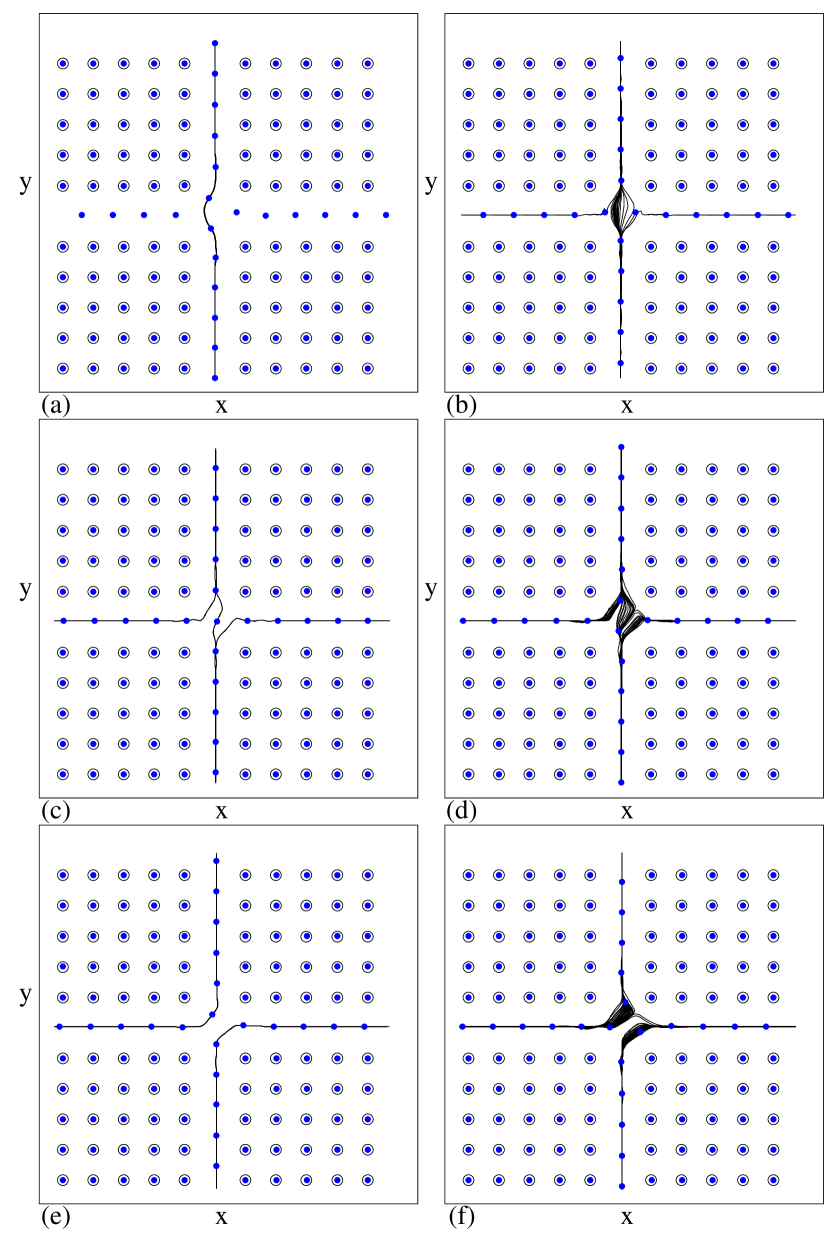
We first consider the vortices under matching conditions , where the number of vortices equals the number of pinning sites in the original square pinning array. In the absence of a drive, the vortices form a square lattice with the interstitial vortices sitting at the locations of the pinning sites that were removed. We illustrate the vortex trajectories for several values of at fixed in fig. 1, and we plot versus in fig. 2(a), versus in fig. 2(b), and versus in fig. 2(c) for the same system. The points marked a-e in fig. 2 correspond to the values of illustrated in fig. 1(a-e).
At , the vortices in the channel are flowing while the vortices in the channel are pinned. The vortices in the channel do not depin until reaches a critical value . For the vortices in the channel are pinned but those in the channel are moving, as indicated by the fact that over this regime in fig. 2(a) while has a finite value in fig. 2(c). Figure 1(a) illustrates the vortex trajectories for where the flow is confined to the direction. At , fig. 1(b) shows that vortices in both channels are moving and that the trajectories are disordered at the channel intersection.
In fig. 1(c) at , the vortex flow at the intersection is ordered or coherent and consists of a mixing flow where vortices approaching the intersection from the left turn upwards into the channel, while a portion of the vortices approaching the intersection from below turn right into the channel. The net flow at the intersection consists of two vortices exiting in the positive direction for every one vortex exiting in the positive direction. The ordered flow regime correlates with a steplike transport anomaly centered around at the point marked c in fig. 2(a). Two peaks in in fig. 2(b) surround this region, while a smooth rounded peak appears in in fig. 2(c). This shows that the vortices remain locked in the ordered flow phase illustrated in fig. 1(c) for a range of . In general, ordered flow phases are associated with all of the transport anomalies in fig. 2. The phases are centered at rational ratios of the external drives with integer, such as at , , or . Figure 1(c) shows the state.
In fig. 2, anomalies at other rational ratios of are visible, with the most pronounced steplike features occurring for cases where and . This type of behavior is very similar to the mode locking found in systems which contain an intrinsic oscillating frequency that locks to an external ac drive [13]. Another intriguing feature is the fact that near the drive at which the system exits a locked phase, such as near the ends of the and steps, decreases with increasing . This is highlighted in the lower right inset of fig. 2(a) for the end of the locked phase. The velocity decrease produces negative differential conductivity where , as shown in fig. 2(b). This indicates that in order for the system to remain locked as it approaches the upper end of the locked phase, the vortices must move more slowly in the direction as increases.
The anomalies we find in the velocity force curves are similar to those observed for vortices or colloids driven over periodic pinning arrays when the particle velocity vector locks to symmetry directions of the pinning array [16, 17, 18]. In these systems, the locking produces clear steps and occurs even in the limit of an isolated driven particle [18]. The phase locking considered here for the crossed channel geometry results from a different mechanism and does not occur in the single particle limit, as we describe below in fig. 3. In addition, there was no negative differential conductivity associated with the phase locking in refs. [16, 17, 18].
Away from the steplike velocity anomalies, the vortex trajectories are disordered, as shown in fig. 1(d) for . Figure 1(e) illustrates the ordered flow phase at , which corresponds to the pronounced anomaly in fig. 2. Also associated with this ordered flow is the dip in highlighted in the lower inset of fig. 2(a), the arctangent-like feature and large negative differential conductivity in in fig. 2(b), and the smooth feature in at point e in fig. 2(c). Figure 1(f) shows the disordered vortex trajectories at , just outside of the state.
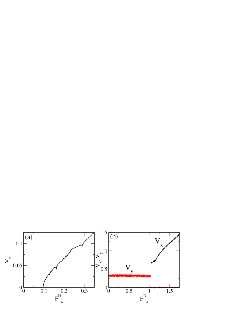
The general features we find in the transport characteristics are independent of the rate at which is increased, and we find similar features if we vary at fixed . In the upper left inset of fig. 2(a) we show the depinning force for motion in the channel vs . As increases from zero, initially decreases and then begins to increase. The increase occurs when the direction driving force shifts the vortices in the channel closer to the occupied pinning sites along the upper side of the channel, increasing the coupling between the interstitial and pinned vortices and thus increasing the depinning force for the interstitial vortices. The widths of the velocity anomalies are enhanced when the depinning threshold increases. This is illustrated in fig. 3(a) where we plot versus for the same system in fig. 2(a) but with . Both the pinned phase and the state are broader at than at .
We next examine the case of a single interstitial vortex driven through the channels. We remove all but one of the interstitial vortices and initialize this single interstitial vortex in the channel. In fig. 3(b) we plot and versus at showing that in the single particle limit, all the transport anomalies seen in fig. 2 are lost and there is simply a transition from pure direction motion to pure direction motion when increases. This is indicated by the sharp transition to which coincides with the onset of a finite value of . We term this sharp transition a vortex gating effect.
The loss of the phase locking for a single interstitial vortex indicates that collective interactions are responsible for the phase locking in the crossed channel geometry. The discreetness of the vortices arriving at the intersection of the channels permits only an integer number of vortices to move in each of the two directions. The ordered trajectories such as those seen in fig. 1(c,e) distort somewhat but stay ordered as increases, allowing the interstitial vortices to remain in the same phase-locked state over a wider range of . The distortion of the vortex trajectories is also responsible for the negative differential conductivity and the changes in associated with the coherent flow phases. In the case of vortices or colloids moving over periodic pinning sites in Refs. [16, 18], the ordered flow phases consisted of one-dimensional paths oriented along different pinning lattice symmetry angles. These paths cannot distort and so there was no differential negative conductivity in these systems.
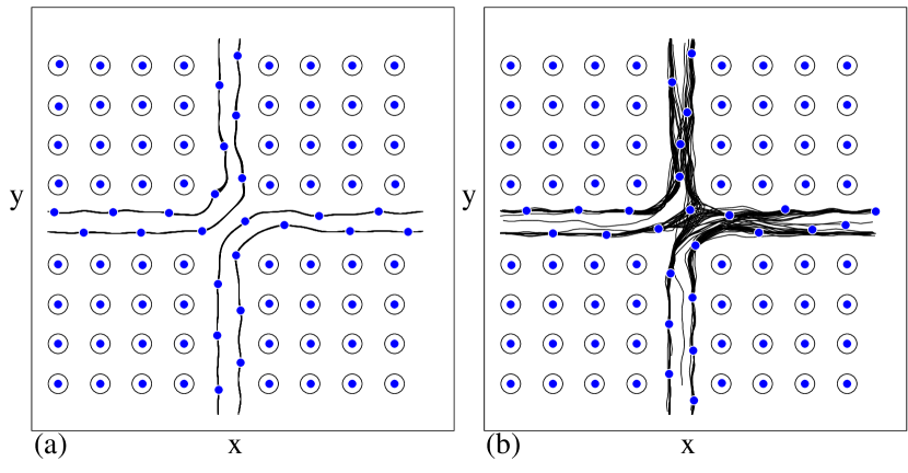
The phase locking illustrated in figs. 1 and 2 occurs for a range of fields and is most prominent for . Within this field range, the interstitial vortices are confined in the channels. In fig. 4(a,b) we plot the vortex trajectories for a sample with . In this case, the vortices in the channel undergo a buckling transition and form a zig-zag pattern. fig. 4(a) illustrates the state where an ordered flow pattern occurs similar to that seen in fig. 1(e). Here there are two staggered moving rows of vortices in each channel. For , shown in fig. 4(b), the vortex trajectories are disordered and there is no steplike anomaly in the transport curves at this point. For , some interstitial vortices begin to penetrate the bulk pinned region away from the channels. These interstitial vortices are generally more strongly pinned than the vortices in the channels; however, for intermediate ranges of and they can become mobile and add extra features to the velocity-force curves. These effects are beyond the scope of this work.
In summary, we studied a square periodic pinning array with crossed easy flow channels for vortex motion formed by the removal of one row and one column of pinning. We show that when a fixed drive is applied in one direction and a slowly increasing drive is applied in the perpendicular direction, a series of phases with coherent vortex flow dynamics occurs which are centered at rational ratios of the two drives. These coherent phases appear as anomalies in the transport curves and are also associated with negative differential conductivity. The phase locking anomalies are distinct from those observed for the velocity vector locking of particles driven at different angles over periodic pinning arrays, which appear even in the single particle case. For the crossed channel geometry, the phase locking occurs due to the discrete nature of the particles. In the single particle limit, the transport anomalies vanish and are replaced by a vortex gating phenomena in which the motion switches abruptly from one channel to the other. We expect that similar effects can occur for particle transport in other systems with quasi-one-dimensional crossed geometries, such as colloidal systems, microfluids, or crossed one-dimensional Wigner crystal systems.
Acknowledgements.
This work was carried out under the auspices of the NNSA of the U.S. DoE at LANL under Contract No. DE-AC52-06NA25396.References
- [1] \NameBaert M., Metlushko V.V., Jonckheere R., Moshchalkov V.V. Bruynseraede Y. \REVIEWPhys. Rev. Lett.7419953269; \NameMartín J.I., Vélez M., Nogués J. Schuller I.K. \REVIEWPhys. Rev. Lett.7919971929; \NameMetlushko V.V., DeLong L.E., Baert M., Rosseel E., Van Bael M.J., Temst K., Moshchalkov V.V. Bruynseraede Y. \REVIEWEurophys. Lett.411998333; \NameWelp U., Xiao Z.L., Jiang J.S., Vlasko-Vlasov V.K., Bader S.D., Crabtree G.W., Liang J., Chik H. Xu J.M. \REVIEWPhys. Rev. B662002212507.
- [2] \NameHarada K., Kamimura O., Kasai H., Matsuda T., Tonomura A. Moshchalkov V.V. \REVIEWScience27419961167.
- [3] \NameBaert M., Metlushko V.V., Jonckheere R., Moshchalkov V.V. Bruynseraede Y. \REVIEWEurophys. Lett.291995157.
- [4] \NameField S.B., James S.S., Barentine J., Metlushko V., Crabtree G., Shtrikman H., Ilic B. Brueck S.R.J. \REVIEWPhys. Rev. Lett.882002067003; \NameGrigorenko A.N., Bending S.J., Van Bael M.J., Lange M., Moshchalkov V.V., Fangohr H. de Groot P.A.J. \REVIEWPhys. Rev. Lett.902003237001.
- [5] \NameKarapetrov G., Fedor J., Iavarone M., Rosenmann D. Kwok W.K. \REVIEWPhys. Rev. Lett.952005167002.
- [6] \NameReichhardt C., Olson C.J. Nori F. \REVIEWPhys. Rev. B5719987937; \NameReichhardt C. Grønbech-Jensen N. \REVIEWPhys. Rev. B632001054510.
- [7] \NameBerdiyorov G.R., Milosevic M.V. Peeters F.M. \REVIEWPhys. Rev. Lett.962006207001.
- [8] \NameRosseel E., Van Bael M., Baert M., Jonckheere R., Moshchalkov V.V. Bruynseraede Y. \REVIEWPhys. Rev. B531996R2983; \NameVan Look L., Rosseel E., Van Bael M.J., Temst K., Moshchalkov V.V. Bruynseraede Y. \REVIEWPhys. Rev. B601999R6998; \NameSilhanek A.V. et al. \Bookto be published.
- [9] \NameReichhardt C., Olson C.J. Nori F. \REVIEWPhys. Rev. Lett.7819972648; \NameMisko V.R., Savel’ev S., Rakhmanov A.L. Nori F. \REVIEWPhys. Rev. Lett.962006127003; \NameReichhardt C. Olson Reichhardt C.J. \REVIEWPhys. Rev. B792009134501.
- [10] \NameBesseling R., Kes P.H., Dröse T. Vinokur V.M. \REVIEWNew J. Phys.7200571.
- [11] \NameGrigorieva I.V., Geim A.K., Dubonos S.V., Novoselov K.S., Vodolazov D.Y., Peeters F.M., Kes P.H. Hesselberth M. \REVIEWPhys. Rev. Lett.922004237001.
- [12] \NameYu K., Heitmann T.W., Song C., DeFeo M.P., Plourde B.L.T., Hesselberth M.B.S. Kes P.H. \REVIEWPhys. Rev. B762007220507.
- [13] \NameKokubo N., Besseling R., Vinokur V.M. Kes P.H. \REVIEWPhys. Rev. Lett.882002247004; \NameKokubo N., Sorop T.G., Besseling R. Kes P.H. \REVIEWPhys. Rev. B732006224514.
- [14] \NameKemmler M., Bothner D., Ilin K., Siegel M., Kleiner R. Koelle D. \REVIEWPhys. Rev. B792009184509.
- [15] \NameSilhanek A.V., Van Look L., Raedts S., Jonckheere R. Moshchalkov V.V. \REVIEWPhys. Rev. B682003214504; \NameVillegas J.E., Gonzalez E.M., Montero M.I., Schuller I.K. Vicent J.L. \REVIEWPhys. Rev. B722005064507; \NameGonzalez E.M., Nunez N.O., Anguita J.V. Vicent J.L. \REVIEWAppl. Phys. Lett.912007062505.
- [16] \NameReichhardt C. Nori F. \REVIEWPhys. Rev. Lett821999414.
- [17] \NameKorda P., Taylor M.B. Grier D.G. \REVIEWPhys. Rev. Lett.892002128301; \NameMacDonald M.P., Spalding G.C. Dholakia K. \REVIEWNature (London)4262003321; \NameGopinathan A. Grier D.G. \REVIEWPhys. Rev. Lett.922004130602.
- [18] \NameLacasta A.M., Sancho J.M., Romero A.H. Lindenberg K. \REVIEWPhys. Rev. Lett.942005160601; \NameHermann J., Karweit M. Drazer G. \BookarXiv:0904.2538 preprint (2009).
- [19] \NameMangold K., Leiderer P. Bechinger C. \REVIEWPhys. Rev. Lett.902003158302.
- [20] \NameKöppl M., Henseler P., Erbe A., Nielaba P. Leiderer P. \REVIEWPhys. Rev. Lett.972006208302.
- [21] \NameBelloul M., Engl W., Colin A., Panizza P. Ajdari A. \REVIEWPhys. Rev. Lett.1022009194502.
- [22] \NamePiacente G. Peeters F.M. \REVIEWPhys. Rev. B722005205208.