Stress orientation of second-phase in alloys: hydrides in zirconium alloys 111A portion of this paper was presented in MS&T’08, October 5-9, 2008, Pittsburgh, Pennsylvania, USA.
Abstract
A model for precipitation of the plate-shaped second-phase under applied stress is presented. The precipitates in the matrix-precipitate system are represented by their local volume fraction and an orientation parameter that defines the alignment of a precipitate platelet in a given direction. Kinetic equations, based on diffusion theory and classical nucleation theory, are used to describe the time evolution of and . The model is used to describe the stress orientation of hydrides in Zr-alloys in light of experiments.
I Introduction
Stress-induced orientation of second-phase particles occurring during precipitation is ubiquitous in many metallurgical systems. Stress orientation is referred to the selective precipitation of a second-phase on a preferred habit plane, caused by the application of an external stress during aging or cooling. For example, in the Ti-H system, hydride precipitation has been observed to occur under an applied tensile stress, upon which titanium hydrides form on the titanium habit plane oriented most nearly perpendicular to the stress axis Louthan (1963). Similarly, in polycrystalline zirconium alloys, it has been observed that stress-orientation of hydrides occurs under tensile stresses, where hydride platelets would get aligned perpendicular to the stress axis and can lie in specific habit-planes; namely on either or crystal planes Louthan and Angerman (1963). Under compressive stresses, however, hydride platelets tend to orient parallel to the direction of applied stress Louthan and Marshall (1963).
The stress orientation effect has also been observed in Fe-N alloys, in which Fe16N2 platelets ( phase) precipitate on a specific habit plane perpendicular to the direction of applied tensile stress Nakada et al. (1967); Tanaka et al. (1978). Other alloy systems exhibiting stress orientation effects include Ni-base alloys with Ni-Nb precipitates Oblak et al. (1974), Fe-Mo-Au with Au particles Sauthoff (1977), and Al-Cu alloys with second-phase particles Hosford and Agrawal (1975); Eto et al. (1978); Skrotzki et al. (1996). Similarly, favoured orientation of precipitates has been observed in ferromagnetic materials, when the material is cooled or heat-treated below its Curie temperature in magnetic field. For instance, magnetic field orienting of Fe16N2 platelets in Fe-N solid solution and alignment of disc-shaped nitrogen atom clusters on the {001} matrix planes of a nitrogen ferrite alloy in the presence of magnetic field Neuh user and Pitsch (1971); Ferguson and Jack (1985); Sauthoff and Pitsch (1987).
The precipitation of titanium hydride in titanium and zirconium hydride in zirconium alloys indicates that the stress orientation of the hydride platelets occurs through orientation of nuclei rather than through selective growth after the critical nucleus size has been reached Louthan (1963); Louthan and Angerman (1963); Louthan and Marshall (1963); Ells (1970); Hardie and Shanahan (1975); Sakamoto and Nakatsuka (2006). Likewise, quantitative metallographic studies indicate that -phase alignment in Al-Cu alloys occurs during nucleation and not under the subsequent growth Eto et al. (1978); Skrotzki et al. (1996).
In this paper, we present a model for kinetics of precipitation of second phase in solid solution under an applied stress. The model may be considered as a mean field description of the matrix-precipitate system, in which the plate-like precipitates are characterized by their volume fraction and a parameter describing their orientation in the matrix. We further assume that second-phase orientation occurs during the nucleation stage of the precipitation process. Section II describes the model for precipitation kinetics and stress orientation. In section III, a case of hydride precipitation and orientation in a zirconium alloy is considered, where the material-dependent parameters entering the model are quantified in light of experimental data. The paper concludes with a discussion of results.
II Model
II.1 Precipitation kinetics
A simple geometrical model for the plate-shaped precipitates in solid solution is envisioned. The precipitates consist of a regular array of parallel ellipsoids embedded in a metal matrix. The sample material, initially at some high temperature, is cooled below the solubility line. Precipitation proceeds by diffusion of solute atoms from the metal matrix to locations, e.g. dislocation lines and/or grain boundaries, where second-phase particles form. A model analogous to that used by Ham Ham (1959) for describing precipitation of solute atoms on dislocations is considered (see appendix A). In this model, the precipitated fraction of excess solute can be calculated as a function of time fairly accurately by the simple relationship of the form: , where , is the inter-precipitate distance, the lowest eigenvalue of the prevailing diffusion equation, and is the solute diffusivity. Here is a solution of the kinetic equation
| (1) |
It is worth noting that Eq. (1) pertains to a class of kinetic equations used to describe the overall precipitation process of excess solute Jain and Hughes (1978). Now in our convention, we put , where is the precipitate volume fraction in equilibrium, i.e. after infinite time if the current temperature and stress state were held constant. Hence Eq. (1) is transformed to
| (2) |
which gives the rate of change for the precipitate volume fraction at a given point in the material. Equation (2) can be solved, subject to an initial condition, , and the condition that and are constant, yielding
| (3) |
We consider now a material in which the solubility limit for precipitation is identical to the solubility for dissolution. The solute solubility is thus assumed to be independent of the heating/cooling history and depends only on the current state of the material. We should note that is a unique function of concentration, temperature and pressure in the considered material, and can be calculated from the phase diagram by use of the lever rule
| (4) |
where is the total solute concentration in the material and and denote the respective lower and upper boundary of the mixed phase region of the phase diagram (temperature vs. concentration). Hence, is the solubility limit in the matrix phase. Equation (4) is valid for . It follows that our assumption of constant in deriving Eq. (3) implies that temperature, pressure and solute total concentration are supposed to be non-varying.
II.2 Stress orientation
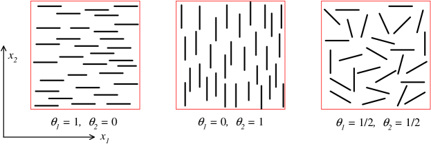
We consider a material with precipitate volume fraction and precipitate mean orientation characterized by the parameters , which are the fractions of platelets aligned with their principal axis along the coordinate directions ; see Fig. 1 for a two-dimensional representation. The volume fraction of platelets aligned with the i:th coordinate axis, , is then simply . Hence, its time derivative is
| (5) |
Next, we make the ansatz
| (6) |
where is the fraction of platelets nucleated in the -direction at a given instant. is a function of the current temperature and stress state, and it also depends on the density of precipitate habit planes aligned in the :th direction. The latter quantity is linked to microstructural properties of the material, e.g. the texture and grain shape. Combining Eqs. (5) and (6) gives
| (7) |
Equation (7) provides the evolution laws for the precipitate orientation parameters . It should be emphasized that only when , i.e. the precipitate mean orientation is assumed to change as a result of nucleation only. If precipitates dissolve, then , and are unaffected. This means that the rate of dissolution is supposed to be the same for all precipitates, irrespective of their orientation.
From classical nucleation theory, the fraction of platelets nucleated in the -direction is calculated as (Puls (1985) and in particular appendix to Jernkvist and Massih (2008))
| (8) |
where ; is the fraction of platelets nucleated in the -direction under stress-free conditions, the critical volume for nucleation of a new phase, , the absolute temperature, the Boltzmann constant, the stress tensor, and the differential misfit (transformation) strain tensor. For an oblate spheroid with major and minor radii and , , where the asterisk symbol signifies the critical values for nucleation.
Under constant temperature and stress, Eq. (7) can be solved, subject to an initial condition , yielding
| (9) |
where we utilized Eq. (3) with and is at equilibrium, viz.
| (10) |
In a plane, , and therefore a single differential equation is sufficient to describe the change in the precipitate mean orientation.
Let us now consider a tubular geometry in which the precipitate orientation is referred to the polar coordinates , with and . The differential misfit (transformation) strain tensor is then defined through
| (11) |
where the right-hand-side terms are the unconstrained transformation strain tensors for radially and circumferentially aligned precipitates, respectively. We note that the fraction of precipitates nucleated in the radial direction under stress-free conditions, , is related to the fraction of precipitate habit planes parallel to the radial direction. This depends on microstructural properties of the material, such as crystallographic texture and grain shape. For Eq. (8) to be non-trivial, we require that .
Let us write Eq. (8) in a compact form
| (12) |
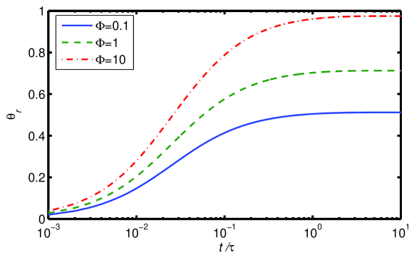
where is a scaled energy parameter. In Fig. 2, we have plotted as a function of the reduced time () and parameter using Eqs. (9)-(12). In this calculation, we have assumed and .
III Precipitation of hydrides in zirconium alloys
Past theoretical studies on the effect of hydride reorientation in zirconium alloys have shown that the preferential orientation of hydride precipitates under stress is most effective during the nucleation stage of the precipitation Ells (1970); Puls (1985). It is argued that the driving force for orienting under stress can be a substantial fraction of the overall force during nucleation. Furthermore, it is indicated that hydride growth is unlikely to play a role in preferential orientation Ells (1970); Puls (1985).
| Parameter | unit | source |
|---|---|---|
| wppm | Pan et al. (1996) | |
| wppm | Pan et al. (1996) | |
| wppm | Zuzek et al. (2000) | |
| m2/s | Sawatzky et al. (1981) |
Let us first identify material-dependent parameters in the model described in the foregoing section for the case of hydrogen in a Zr-alloy, namely Zr-2.5wt% Nb (Zr-2.5Nb), Northwood and Kosasih (1983). The phases in the binary Zr-H system are as following Zuzek et al. (2000): There are two allotropic forms of zirconium, namely hexagonal closed-pack (hcp) -Zr and body-centered cubic (bcc) -Zr, two stable hydride phases, face-centered cubic (fcc) -hydride ( ZrH1.5) and face-centered tetragonal (fct) -hydride ( ZrH2). In addition, there is one metastable hydride phase, -hydride, with fct structure ( ZrH), which can exist at the lower temperatures in the ()-phase region. The -hydrides appear usually as plate-like (oblate spheroid) particles, whereas the -hydrides are commonly observed as needle-like ellipsoidal particles.
We first regard the equilibrium hydride volume fraction as expressed by Eq. (4). Two material-dependent parameters appear in this equation, i.e. and . They are considered to be functions of temperature only (table 1), despite a slight pressure dependence of these quantities. We should also note that differs for hydride dissolution and hydride precipitation Pan et al. (1996). The -line phase boundary was obtained by an exponential fitting to the data for the H-Zr system presented in Zuzek et al. (2000). We next estimate the relaxation time in Eq. (9). As noted earlier, where is the observed distance between hydrides and the hydrogen diffusivity in -phase zirconium (table 1). For small hydride volume fractions, can be related to platelet thickness via Kearns (1968)
| (13) |
where and are the volume fractions of the metal and hydride, respectively. Moreover, in a Zr-H alloy, Kearns Kearns (1958) observed that for hydrogen concentrations up to 1000 weight parts per million (wppm), , where is wppm hydrogen. With this relation, the relaxation time is determined from measured values of rather than . For example, for wppm, m (typical observed value), K and given in table 1, we calculate s. Kearns Kearns (1958) found that a dissolution kinetics model similar to that in Eq. (2) fitted well his experimental data. He measured the time needed for complete dissolution of hydrides at constant temperatures, ranging from 570 to 690 K. The hydrogen content of his Zircaloy-4 samples was from 60 to 205 wppm.
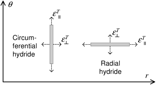
To calculate the fraction of hydrides nucleated in a given direction using Eq. (8), we need the components of the differential misfit strain tensor in Eq. (11). Carpenter Carpenter (1973) calculated the unconstrained misfit strains associated with the formation of - and -hydride in -phase zirconium, and expressed the strain components with respect to crystallographic orientations of the zirconium matrix; see table 2. Since -hydride platelets form on planes, which are roughly aligned with the zirconium basal plane, the direction in table 2 corresponds approximately to the platelet thickness (normal) direction. Hence, the misfit strain is approximately normal to -hydride platelets, and parallel to the platelets. With these approximations, it follows from Fig. 3 that the misfit strain components for radial hydrides are
| (14) |
Likewise, for circumferential hydrides
| (15) |
Accordingly, the components of the differential misfit strain tensor in Eq. (11) become: , , and Introducing and these relations into Eq. (12), we find , with . This relation for can be used for cylindrical geometries to calculate the fraction of -hydride platelets that nucleate with a radial orientation, given the stress state and temperature in the material. We may treat and as material dependent input parameters to the model, which can be determined from hydride reorientation experiments on a particular material. For example, Hardie and Shanahan’s (HS) stress reorientation experiment on Zr-2.5Nb containing 100 wppm hydrogen (cf. Fig. 8 of Hardie and Shanahan (1975), samples cooled from 400∘C) gives KPa-1 and . Employing these constants for MPa, , K, we obtain (cf. Fig. 2). We should note that Eq. (8) is formulated in terms of true stress, which means that the stress tensor comprises contributions from applied loads as well as possible residual stresses, thermally induced stresses, etc. Hydride reorientation experiments show that residual stresses can have a significant impact on hydride orientation Leger and Donner (1985); Singh et al. (2006).
| Direction in -phase | Unconstrained misfit strain | |
|---|---|---|
| zirconium matrix | -hydride | -hydride |
| 0.0720 | 0.0570 | |
| 0.0458 | 0.0055 | |
| 0.0458 | 0.0564 | |
We now rewrite explicitly the expression for the number of platelets nucleated in the radial direction, Eq. (8), for , namely
| (16) |
It is important to point out that the supposition that the parameter is a material constant at best is a rough approximation. There exists a supercooling effect, which shows that the formation of a new phase occurs at a temperature below the equilibrium solvus temperature by a deviation . In other words, the critical volume or the Gibbs energy of formation are decreasing functions of (see e.g. Porter and Easterling (1981)). Furthermore, it can be shown that for a plate-like oblate spheroid precipitate (see appendix to Jernkvist and Massih (2008))
| (17) |
and the critical energy for nucleation
| (18) |
with the nucleation energy density expressed as
| (19) |
Here , , are the concentrations of the solute (hydrogen) in the precipitate (hydride), in the supersaturated matrix (Zr), and in the matrix in equilibrium with the precipitate, respectively. Also, is the misfit strain energy (self-energy) per unit volume, and , are the specific interface energies of the flat and the edge side of the platelet, respectively Sauthoff (1976). The interfacial energy may be estimated from measured data on nucleation rate Sauthoff (1981), but to our knowledge such data are unavailable for the hydride-Zr system. Furthermore, we should note that hydrogen in the matrix depletes during the formation of a new phase and therefore is a time-dependent variable. More precisely, we may relate to the hydride volume fraction and the total hydrogen concentration in the material in the manner
| (20) |
where is governed by Eq. (2). Finally, for the calculation of the relaxation time , we relate the inter-hydride distance in the specimen to the volume fraction of hydride by assuming
| (21) |
where and are observational constants. Thus to account for the effect of supercooling, the two ordinary differential equations (2) and (7) need to be solved simultaneously, by making use of Eqs. (4) and (16)-(21).
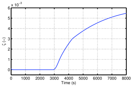
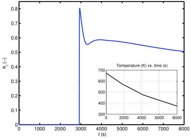
Using the aforementioned method, we attempt to simulate an experiment by Hardie and Shanahan Hardie and Shanahan (1975) on stress orientation of hydrides in Zr-2.5Nb specimens under non-isothermal conditions. More specifically, we consider a case in HS’s series C tests where the specimen contained wppm hydrogen. The specimen was heated from room temperature to 673 K to dissolve the hydrides, then cooled under a constant stress (150 MPa) at rates 3.3 Ks-1 (673 to 573 K), 2.5 Ks-1 (573 to 473 K) and 1.7 Ks-1 (473 to 373 K). In our computations, the variable in Eq. (4) is the hydrogen solubility for precipitation . Our analyses show that the choice of has a strong impact on the calculated results, since it determines the onset of hydride precipitation during a cooling sequence. Therefore, we assume that , where is a scaling factor, , and is given by the expression for in table 1. We have used the following set of values for the model parameters: , MJm-3, Jm-2, Jm-2, m, m, , and . In addition, we consider -hydride with , , the molar volume m3mol-1, and the Avogadro constant. Moreover, we have assumed as given in table 1.
We have solved the system of the aforementioned equations by using the Runge-Kutta algorithm of order 4 and 5 Quarteroni and Saleri (2003). The results for the time variation of the hydride volume fraction and the orientation parameter are depicted in Fig. 4. It is seen that nucleation of hydride occurs immediately around 3000 s after the start of cooling, corresponding to the temperature of about 525 K. Then , after a sharp dip to a shallow minimum, raises and falls slowly to a near equilibrium value of , at s, K. This value is close to the experimental result of Hardie and Shanahan (cf. Fig. 8 of Hardie and Shanahan (1975)). We have also tabulated the results of computations at K for several initial (total) hydrogen concentrations: wppm, and applied stresses: MPa. Table 3 shows these results for . The second column in this table can be compared with HS’s experimental data (Fig. 8 of Hardie and Shanahan (1975)), which shows a reasonable agreement. The corresponding calculated hydride volume fractions for the three hydrogen concentrations are: . Since the nucleation energy density is the driving force for hydride formation, we have listed their calculated values in table 4. For example, at wppm, MPa, MJm-3, and so on.
 |
 |
| (-) | (wppm) | ||
|---|---|---|---|
| (MPa) | 100 | 200 | 300 |
| 100 | 0.0765 | 0.2381 | 0.4067 |
| 150 | 0.5052 | 0.8071 | 0.8461 |
| 200 | 0.9153 | 0.9772 | 0.9797 |
| 250 | 0.9912 | 0.9980 | 0.9982 |
| 300 | 0.9991 | 0.9998 | 0.9998 |
| (MJm-3) | (wppm) | ||
|---|---|---|---|
| (MPa) | 100 | 200 | 300 |
| 100 | 552 | 540 | 537 |
| 150 | 554 | 541 | 540 |
| 200 | 555 | 543 | 540 |
| 250 | 556 | 543 | 541 |
| 300 | 558 | 545 | 542 |
IV Discussion
The behaviour seen in Fig. 4 may be interpreted as an expression of supercooling effect, whereupon a metastable configuration (local minimum) appears before the system settles down to a more stable configuration. This effect, despite its importance, to our knowledge, has not been studied experimentally in a quantitative fashion for the Zr-H system. In our study as in the earlier investigation Puls (1985), we assumed that stress orientation of hydrides occur primarily during the nucleation stage of precipitation. The kinetics of nucleation is characterized by the nucleation rate. The steady-state nucleation rate gives the number of (hydride) nuclei forming per unit volume and time, expressed as Balluffi et al. (2005), , where is the Zeldovich factor (), the frequency factor, i.e. the rate atoms add to the critical nucleus, the number of sites available for nucleation, and is given by Eq. (18). Note that , so a slight increase in gives a significant rise to the nucleation rate.
Nucleation experiments similar to that of Tanaka et al. Tanaka et al. (1978) made on the Fe-N system, are valuable to determine the hydride nucleation rate as well as the degree of hydride orienting as a function of hydrogen concentration and applied stress. Such experiments would allow to identify or verify some of the model parameters used in the computations here.
Finally, an issue worth addressing is the role of late-stage growth or coarsening on hydride stress orienting. The late-stage growth follows the Lifshitz-Slyozov law Lifshitz and Slyozov (1961), expressed as
| (22) |
where is the mean particle (precipitate) radius at time , the mean particle radius at time when coarsening commences, and is the rate constant for diffusion-limited coarsening. Such a behaviour has been observed for growth of hydride platelets in Zr-2.5Nb alloy Shalabi and Meneley (1990). It can be shown that the maximum rate of particle size increase occurs at , and particles with sizes will disappear with relatively high shrinkage rates.
Following the arguments of Puls Puls (1985), based on a model by Sauthoff Sauthoff (1976), we consider a tubular specimen of Zr-2.5Nb containing hydrides, which at time after nucleation half of the hydride platelets are radially oriented and the rest are circumferentially oriented across the tube wall. If the major radii of these platelets are denoted by and , respectively, Sauthoff Sauthoff (1976) obtained a relationship between these radii using the Gibbs-Thomson-Freundlish relation, namely
| (23) |
where is the eccentricity (ratio of minor to major radii), and . By setting , Eq. (23) gives a minimum mean radius for which even the largest circumferentially oriented hydrides will no longer grow. Using the data in the foregoing section with MPa and , we obtain m.
In order to attain a complete orienting in radial direction, all the circumferential hydrides must disappear in addition to half of the radial ones. Hence, there would be a factor of four decrease in the total number of hydride platelets. Since during coarsening the total precipitate volume remains practically constant, this decrease corresponds to a factor of increase in the mean platelet radius.
We may calculate, for the case of Zr-2.5Nb discussed in the foregoing section, the time needed to increase the minimum platelet radius by a factor of 1.6. Boyd and Nicholson Boyd and Nicholson (1971) have calculated the coarsening rate constant for disc-shaped precipitates, viz.
| (24) |
Using and in table 1, and other data listed previously, Eq. (24) yields m3s-1 at K. Thus to increase the minimum platelet radius of m by a factor of 1.6 would take about 15 s at K, according to Eq. (22). Therefore stress orienting of hydride platelets would be possible in Zr-2.5Nb alloy during coarsening.
V Conclusions
In this paper, we have presented a generic model for calculation of stress-induced orientation of disc-shaped precipitates in alloys. The model is applicable to situations where the stress orienting occurs primarily during the nucleation stage of the precipitation process. We have identified parameters appearing in the model for the case of hydride precipitates in a zirconium alloy. The model can be used to compute the degree of orienting as a function of stress, temperature and time. It also can be extended to account for the effect of supercooling during phase transition.
Acknowledgments
The work was supported in part by the Knowledge Foundation of Sweden under the grant number 2008/0503.
Appendix A Diffusion model for precipitation
An idealized configuration for second-phase precipitate metal composite is considered. The hydrides are a regular array of parallel cylinders embedded in a metal matrix. We posit that solute precipitation is diffusion-controlled and diffusion occurs only in the radial direction (cylindrical symmetry). Furthermore, there is no imposed external force on the solute atoms. The solute concentration is a function of space and time obeying the diffusion equation of the form
| (25) |
This equation is solved subject to the following initial and boundary conditions
| (26) | ||||
| (27) | ||||
| (28) |
where is the radius of the cylinder and that of the cell enclosing the cylinder assumed to be impenetrable. The impenetrability (zero flux) condition is equivalent to the requirement that shall have the symmetry of a regularly spaced lattice of identical cylinders per unit area on which precipitation occurs Ham (1959). The solution for this boundary value problem Ham (1959); Carslaw and Jaeger (1959) is expressed as
| (29) |
where
| (30) |
and the eigenvalues are the roots of the transcendental equation
| (31) |
Here and are the Bessel functions of the first and second kind, respectively, of order .
Let us calculate the fraction of precipitates of the excess solute as it evolves with time. This is related to the total number of solute atoms remaining between and , expressed as
| (32) |
Denoting the quantity of solute in the metal matrix after infinite time by , then the precipitated fraction of particles is . Combining Eqs. (29) and (32), we write
| (33) |
which is essentially the result obtained by Ham Ham (1959). Considering now Eq. (33), we note that each eigenmode decays exponentially with time with a different decay time . Since the large- eigenmodes decay more rapidly with time, only the most slowly decaying eigenmode remains in the long-time limit, namely
| (34) |
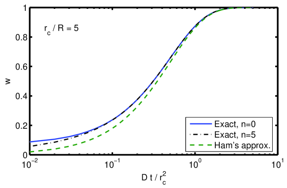
This relation can be compared with Ham’s approximate expression for , namely , with and . Evaluations of the precipitate fraction as a function of made according to Eqs. (34), (33) with six term in the sum, and Ham’s approximate expression show that Eqs. (34) and (33) yield almost identical results, whereas Ham’s approximate relation gives a slightly lower for , see Fig. 5.
References
- Louthan (1963) M. R. Louthan, Trans. Metall. Soc. AIME 227, 1166 (1963).
- Louthan and Angerman (1963) M. R. Louthan and C. L. Angerman, Trans. Metall. Soc. AIME 236, 221 (1963).
- Louthan and Marshall (1963) M. R. Louthan and R. P. Marshall, J. Nucl. Mater. 9, 170 (1963).
- Nakada et al. (1967) Y. Nakada, W. C. Leslie, and T. P. Churay, Trans. ASM 60, 223 (1967).
- Tanaka et al. (1978) Y. Tanaka, A. Sato, and T. Mori, Acta Metall. 26, 529 (1978).
- Oblak et al. (1974) G. M. Oblak, D. F. Paulonis, and D. S. Duvall, Metall. Trans. 5, 143 (1974).
- Sauthoff (1977) G. Sauthoff, Z. Metallkde. 68, 500 (1977).
- Hosford and Agrawal (1975) W. F. Hosford and S. P. Agrawal, Metall. Trans. A 6A, 487 (1975).
- Eto et al. (1978) T. Eto, A. Sato, and T. Mori, Acta Metall. 26, 499 (1978).
- Skrotzki et al. (1996) B. Skrotzki, G. J. Shiflet, and E. A. Starke, Metall. Trans. A 27A, 3431 (1996).
- Neuh user and Pitsch (1971) H. N. Neuh user and W. Pitsch, Z. Metallkde. 62, 792 (1971).
- Ferguson and Jack (1985) P. Ferguson and K. H. Jack, Phil. Mag. B 52, 509 (1985).
- Sauthoff and Pitsch (1987) G. Sauthoff and W. Pitsch, Phil. Mag. B 56, 471 (1987).
- Ells (1970) C. E. Ells, J. Nucl. Mater. 35, 306 (1970).
- Hardie and Shanahan (1975) D. Hardie and M. W. Shanahan, J. Nucl. Mater. 55, 1 (1975).
- Sakamoto and Nakatsuka (2006) K. Sakamoto and M. Nakatsuka, J. Nucl. Sci. Tech. 43, 1136 (2006).
- Ham (1959) F. S. Ham, J. Appl. Phys. 30, 915 (1959).
- Jain and Hughes (1978) S. C. Jain and A. E. Hughes, Proc. Roy. Soc. London, Ser. A 360, 47 (1978).
- Puls (1985) M. P. Puls, in Solute-Defect Interactions, Theory and Experiment, edited by S. Saimoto, G. R. Purdy, and G. V. Kidson (Pergamon Press, Toronto, Canada, 1985), pp. 426–433.
- Jernkvist and Massih (2008) L. O. Jernkvist and A. R. Massih, in Materials Science & Technology 2008 (MS&T’08) (MS&T Partner Societies, 2008).
- Pan et al. (1996) Z. L. Pan, I. G. Ritchie, and M. P. Puls, J. Nucl. Mater. 228, 227 (1996).
- Zuzek et al. (2000) E. Zuzek, J. P. Abriata, A. San-Martin, and F. D. Manchester, in Phase Diagrams of Binary Hydrogen Alloys (ASM Int., Materials Park, OH, USA., 2000), pp. 309–322.
- Sawatzky et al. (1981) A. Sawatzky, G. A. Ledoux, R. L. Tough, and C. D. Cann, in Metal-Hydrogen Systems, edited by T. N. Veziroglu (Pergamon Press, 1981), pp. 109–120.
- Northwood and Kosasih (1983) D. O. Northwood and U. Kosasih, Int. Metals Rev. 28, 92 (1983).
- Kearns (1968) J. J. Kearns, J. Nucl. Mater. 27, 64 (1968).
- Kearns (1958) J. J. Kearns, Tech. Rep. WAPD-TM-147, Westinghouse Bettis (1958).
- Carpenter (1973) C. J. C. Carpenter, J. Nucl. Mater. 48, 264 (1973).
- Leger and Donner (1985) M. Leger and A. Donner, Can. Metall. Quart. 24, 235 (1985).
- Singh et al. (2006) R. N. Singh, R. L. Mikin, G. K. Dey, D. N. Saha, and P. Ståhle, J. Nucl. Mater. 359, 208 (2006).
- Porter and Easterling (1981) D. Porter and K. Easterling, Phase Transformations in Metals and Alloys (Van Nostrand Reinhold, Wokingham, England, 1981).
- Sauthoff (1976) G. Sauthoff, Z. Metallkde. 67, 25 (1976).
- Sauthoff (1981) G. Sauthoff, Acta Metall. 29, 637 (1981).
- Quarteroni and Saleri (2003) A. Quarteroni and F. Saleri, Scientific Computing with MATLAB (Springer, Berlin, Germany, 2003).
- Balluffi et al. (2005) R. W. Balluffi, S. M. Allen, and W. C. Carter, Kinetics of Materials (Wiley Interscience, Hoboken, New Jersey, USA, 2005), chapter 19.
- Lifshitz and Slyozov (1961) I. M. Lifshitz and V. V. Slyozov, J. Phys. Chem. Solids 19, 35 (1961).
- Shalabi and Meneley (1990) A. F. Shalabi and D. A. Meneley, J. Nucl. Mater. 173, 313 (1990).
- Boyd and Nicholson (1971) J. D. Boyd and R. B. Nicholson, Acta Metall. 19, 1379 (1971).
- Carslaw and Jaeger (1959) H. S. Carslaw and J. Jaeger, Conduction of Heat in Solids (Oxford University Press, Oxford, UK, 1959), 2nd ed.