A method to polarise antiprotons in storage rings and create polarised antineutrons
Abstract
An intense circularely polarised -beam interacts with a cooled antiproton beam in a storage ring. Due to spin dependent absorption cross sections for the reaction a built-up of polarisation of the stored antiprotons takes place. Figures-of-merit around 0.1 can be reached in principle over a wide range of antiproton energies. In this process polarised antineutrons with polarisation emerge. The method is presented for the case of a 300 MeV/c cooled antiproton beam.
pacs:
13.88.+epolarisation in interactions and scattering and 29.20.DhStorage rings and 29.27.Hjpolarised beams1 Introduction
The preparation of polarised beams of nucleons and antinucleons at energies in the GeV region poses challenging technical problems. In the case of protons powerful sources of polarised protons exist. Starting from low energies a cascade of accelerators, all equipped with polarisation conserving beam optics, brings the proton beam to its design energy. Antiprotons, however, are produced with high energy proton beams. Large acceptance storage rings are used to collect and cool the produced antiprotons in order to prepare an antiproton beam for physics experiments. The exploitation of the polarisation degrees of freedom in physics experiments plays for antiproton and antineutron induced reactions a similar important role as for other probes e.g. electrons and protons. Challenging physics questions can be addressed with polarised antiproton beams as soon as moderate luminosities, compared to polarised proton beams, can be achieved. In recent publications Ref1 ; Ref2 ; Ref3 the physics motivations and foreseen experimental programs are addressed, previous studies to prepare a polarised antiproton beam are discussed and a method for the preparation of a polarised antiproton beam in the GeV region has been proposed Ref1 . In that proposal antiprotons would be polarised by the spin dependent interaction in an electron polarised hydrogen gas target. The antiproton beam polarisation would reach =0.2-0.4.
The method described in this paper makes use of different reaction cross sections for the two spin projections of antiprotons stored in a storage ring interacting with polarised -radiation. The main ingredients driving the method are described. Limits and possible future directions of the application of the method are addressed. Recent developments in accelerator physics paved the way to the proposed scheme. In sect. 2 the method will be described. In sect. 3 the absorption cross sections will be presented . Sect. 4 deals with practical considerations for an implementation of the method. Sect. 5 addresses the question of preparing an antineutron beam. The article ends with a summary in sect. 6.
2 Method
The method makes use of the different sizes of total absorption cross sections for circularly polarised photons on the antiproton. The antiprotons stored in a ring equipped with a Sibirian snake Ref4 traverse a straight section.
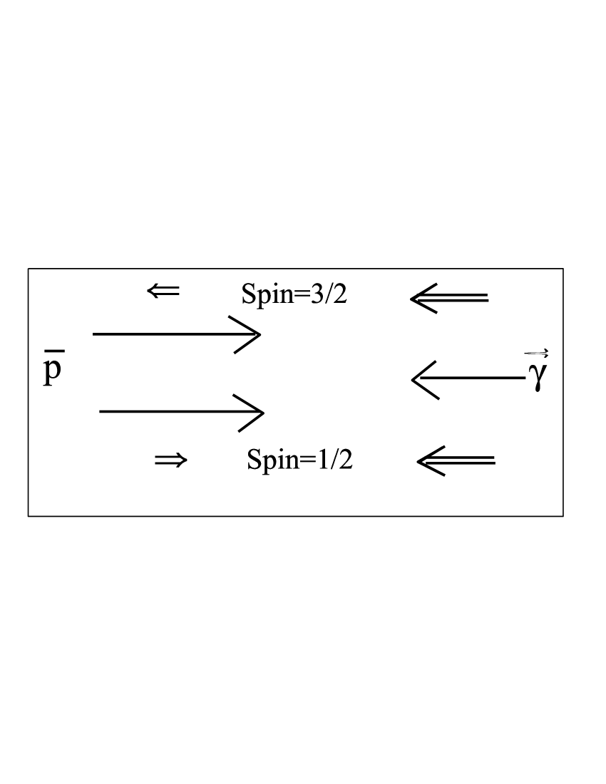
By shining circularly polarised photons against a stream of antiprotons, see fig. 1, total absorption of the photons occurs, provided the photon energy exceeds the pion production thresholds of the reactions , with MeV, and , with MeV. Due to the two possible total spin states of j=3/2 and j=1/2 two total absorption cross sections, and , come into play. The ideal situation of the application of the method would be reached when one of those cross sections would be zero. Then the non disappearance of the other cross section would lead to the loss of that component of the beam in the ring, provided that the absorption process transforms the antiproton into an antineutron or, for the -reaction, the antiproton in the final state escapes the acceptance of the storage ring.
2.1 Cross sections, luminosity
Fig. 2 shows those total cross sections and as a function of the photon energy up to 500 MeV.
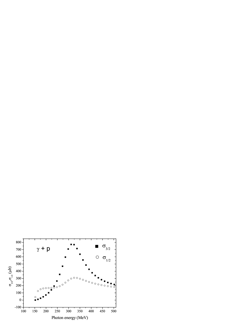
Two energy windows can be seen that can be used to reach high polarisation. A beam polarisation
| (1) |
develops during the interaction period, with and as the stored antiprotons of the 1/2 and 3/2 channels, respectively. Close to the and production thresholds, around a cross section ratio of 9 can be reached, thus, approaching almost the ideal situation. On top of the first antinucleon resonance , a second window for an efficient beam polarisation opens up, a little bit wider on the energy scale than the first one yielding a cross section ratio of 2-3. Reaction rates yield ”decay constants” of the two components of and . As an example that sets the goal for the application of the method, values of and = have been chosen. For those values of the decay constants and using a storage ring filled with unpolarised antiprotons the number of the stored antiproton develops in time as
| (2) |
| (3) |
That development of , the built-up of the polarisation and figure of merit are shown in fig. 3.
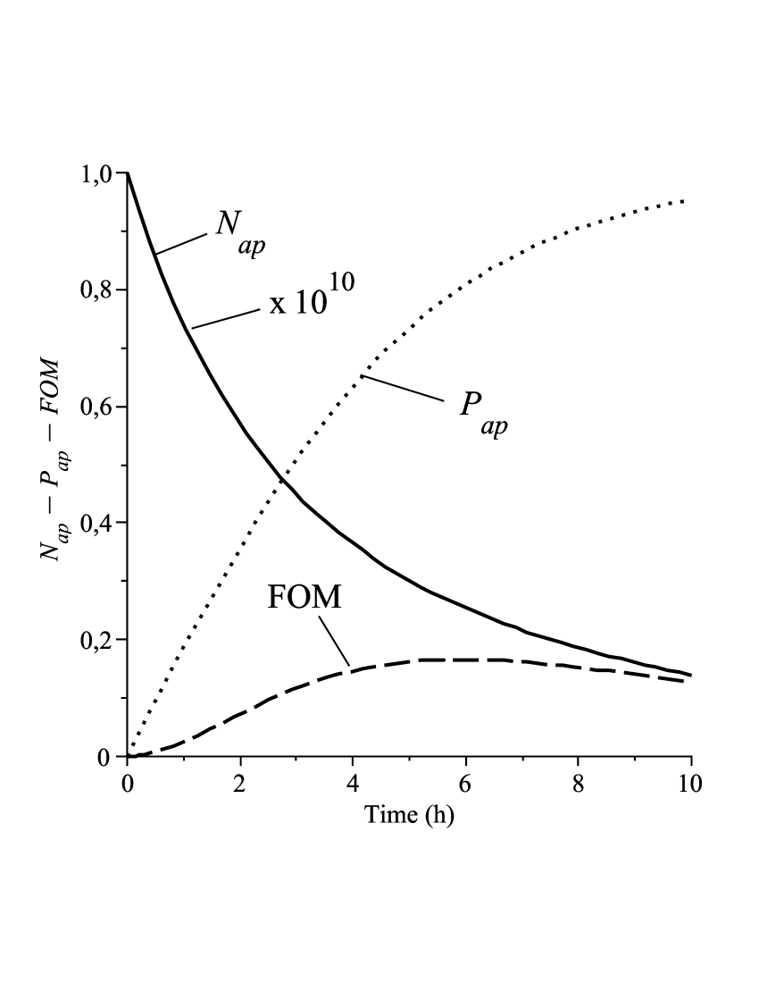
At the maximum of the figure-of-merit with the number of stored antiprotons decreases to with a polarisation of . In the ideal case, with only one absorption channel present, the figure-of-merit could reach a value of Using the value of the decay constant and taking the cross section, e.g. 165 at 190 MeV, shown in fig. 2, the luminosity L results to:
| (4) |
The question will be, whether experimental conditions can be prepared that allow to approach that described goal as shown in fig. 3. Thus, one of the most important tasks consists in preparing an intense circularly polarised photon beam.
2.2 Energy, intensity and polarisation of a photon beam
2.2.1 Energy of the photon beam
The method considered could possibly cover a large range of antiproton energies up into the GeV/c region. In order to define the range of energies two antiproton momenta are considered, 10 GeV/c and 300 MeV/c. For an antiproton beam with a momentum of 10 GeV/c the velocity in units of the velocity of light is 0.9956 and . The energy region close the pion production threshold, is considered first. The photon energy in the laboratory system for 200 MeV photons in the rest system of the antiprotons amounts to . Working in the first resonance region with photons of 310 MeV needs a photon source in the laboratory of . The respective values are MeV for MeV and MeV for MeV for the case of antiproton momenta of 300 MeV/c in a storage ring. The method will be discussed for the 300 MeV/c case.
2.2.2 A suitable photon source
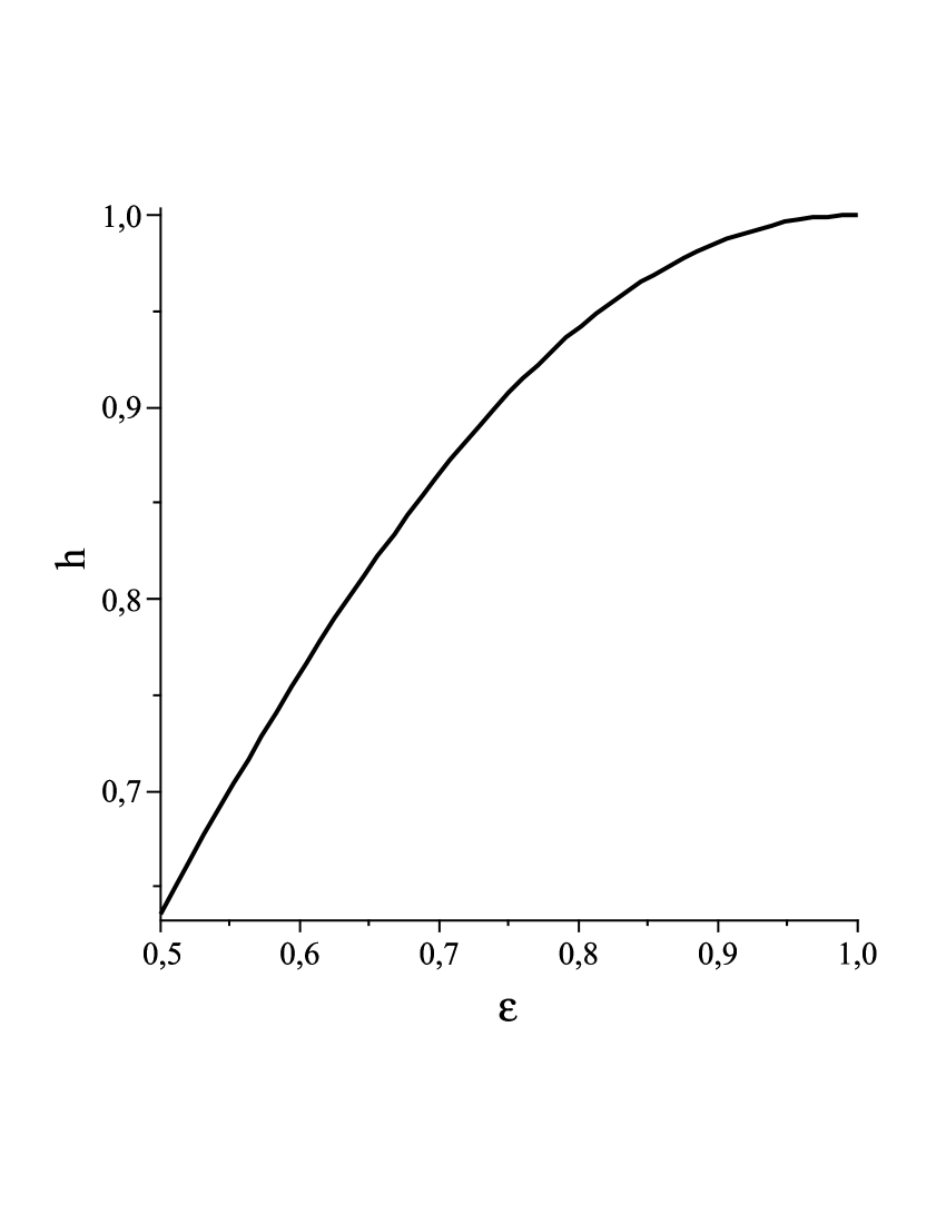
Electron bremsstrahlung provides the only powerful source for that -energy range. In the bremsstrahlung process, a helicity transfer from the electron to the photon takes place. An almost completely circularly polarised photon beam with the polarisation , close to the endpoint of the photon spectrum, can be prepared by a longitudinally polarised electron beam. Fig. 4 shows the degree of helicity transfer h Ref6 for a beam of bremsstrahlung with a 100% polarised electron beam as a function of
| (5) |
3 A closer look to the absorption cross sections and polarised electron sources
The applicability of the method depends on the knowledge of the input data, such as total absorption cross sections, and . However, other issues will be decisive for efficient applications such as high luminosities. In addition, each implementation of such a method depends on the beam optics of the storage ring for a beam of polarised antiprotons and needs a cooled beam. Each energy regime needs special considerations. A new facility FAIR Ref7 will be built at GSI in Darmstadt, Germany. A storage ring, HESR, will be able to store antiprotons in the energy regime . It is anticipated that is the number of antiprotons produced at FAIR in 15 min. will be also the number of antiprotons in the low energy ring considered in the following discussion.
3.1 Experimental data for the total photon proton cross sections
In the last few years the cross section difference on the proton was measured in the photon energy range at the accelerators MAMI, Mainz Ref8 , and ELSA, Bonn Ref9 . From the total absorption cross section , compiled by the particle data group Ref10 , and the cross section difference the cross sections for circularly polarised photons, and , can be extracted:
| (6) |
| (7) |


Photoproduction data have been analyzed and described by the results of calculations based on a phenomenological model. The results of calculations with the computer program MAID Ref3 are shown together with the data in fig(s). 5 and 6. For the purpose of this paper the agreement between the MAID results and the measurements are good enough in order to use the MAID results for the polarised photon cross sections and , see fig. 2. The MAID results allow also to cover the near pion threshold region, not covered by the mentioned experiments.
3.2 Polarised electrons
Polarised electrons are routinely produced via photo emission from GaAs-crystals either in pulsed or dc mode by LASER light, e.g. ref. Ref11 and ref. Ref12 , respectively. Average currents of with a beam polarisation of are achieved. The emittances reached are well adapted to use them for interactions with cooled hadron beams. On several places research is going on to increase the current. At Jefferson Lab. e.g. a dc polarized electron beam with a current of 1 mA has been produced recently.
4 Practical considerations
4.1 A possible implementation of a set-up
Antiprotons are stored in a 300 MeV/c storage ring equipped with cooling equipment and a Sibirian Snake. The circumference of the ring is chosen to be 150 m. There is no need for specially large acceptances for the antiproton ring. The number of stored antiprotons, , is assumed to be evenly distributed over the circumference of the ring. The ring has a straight section in order to install an interaction zone for the bremsstrahlung beam, see fig.7.
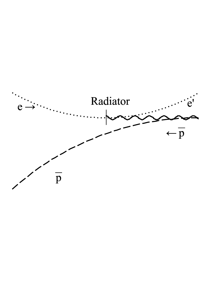
The electron and antiproton beam enter into a strong magnetic field B (e.g. 3 T), perpendicular to their trajectories. The electron beam is fed in the vertical direction from above approaching the trajectory of the antiproton beam, see fig.7. Thereby, the electron beam gets bent upwards in vertical direction, the antiprotons are bent downwards. A radiator is inserted into the electron beam line at the point where the electron beam touches the field free trajectory of the antiproton beam. After the radiator the electron beam will be bent upwards towards a beam dump. The antiproton beam gets hit at the entrance into the magnetic field by the bremsstrahl beam. The beam diameter of the antiproton beam is chosen to be 50 In order to get a large overlap of the antiproton and -beam a focus of around 30 in diameter of the electron beam on the radiator should be accomplished. The beam entrance of the antiproton beam into the magnetic field and the end of the radiator are 10 mm apart. The distance of the electron beam to that entrance point adds up to 230 The antiproton beam passes the radiator at a distance of around 150 The characteristic bremsstrahl angle, without multiple scattering, leads to a distance of 25 at the entrance point of the antiprotons into the magnetic field. That whole scheme is not optimized at all. It should demonstrate that it is possible to prepare a bremsstrahl beam and keeping the electron and antiproton beam separate. E.g. by increasing the the magnetic field by a factor of two and decreasing the momentum of the antiprotons by a factor of two the critical distances mentioned above reach the scale of 0.5 mm.
4.2 The number of photons and the luminosity
, the number of polarised photons hitting the antiprotons, is the last number missing in order to calculate the luminosity. The relation
| (8) |
with as the fraction of the radiation length of the radiator, allows to calculate with an adequate accuracy: =2.8 with =0.06 and s-1, coresponding to a 200 A beam current. The integration range covers the region of dominance of the total absorption cross section. The luminosity can be written as:
| (9) |
where and characterize the Gaussian transverse beam profiles. The diameters of the beams have been chosen, as discussed above, to d=50 and the frequency of the bunch crossing is determined by the length of the antiproton storage ring and the velocity of the antiprotons. With those numbers the luminosity adds up to: . That result is almost identical with the result of eq. 3. The uncertainties entering as discussed above, mainly due to the chosen geometry in the interaction zone, may add up to a factor of three to five. The value of has been used routinely at Jefferson Lab. for carrying out photon induced reactions. An explicit calculation with the bremsstrahl spectrum, the degree of polarisation of electron beam of 85%, the unpolarized contribution due to the not complete helicity transfer, see fig.4, leads to a reduction of the figure-of-merit (FOM). That reduction depends on which photon energy range will be covered. Selecting the threshold region, the figure-of-merit reaches 0.18. Choosing, the region where FOM adds up to 0.075.
5 Preparation of an antineutron beam
For the -energy region the range of transverse momenta of the photoproduced antineutrons covers a momentum range of independently of the momenta of the antiprotons. Accordingly, it is much more favourable to prepare an antineutron beam using high energy storage rings for the antiprotons due to kinematical focusing. However, looking at fig.7 it might not be possible to reach high energies because of keeping the electron and antiproton beam separate. For the case of a 10 GeV/c antiprotons, certainly, the antiproton beam stays almost on his field free trajectory. That means the radiator has to be taken out of the free field position and positioned above it. The very low electron energy of only 10 MeV may still allow to find a configuration that crossing of the bremsstrahlung with the antiprotons becomes possible without interference of the electron and and antiproton beam. In such a case a preparation of an antineutron beam with high polarisation can be prepared. The intensities would be limited by the production rate of antiprotons.
6 Summary
In sect. 2 a method has been identified that could have the potential to
prepare a polarised antiproton beam in a storage ring. By making
use of two largely different photon absorption cross sections, and , one of the antiproton spin
projection gets enriched during the absorption processes and thus leads to a
polarised antiproton beam. A suitable circularly polarised photon beam can be prepared
by using a bremsstrahlung beam.
In addition, that method allows to extract from the stored antiprotons in
the ring, via the reaction a beam of
polarised antineutrons.
That method allows also, by switching the polarisation of the electron,
a measurement of the polarisation of
the stored antiproton beam to a high degree of precision by detecting
the produced antineutrons.
The advantage to use real photons resides in the fact
that one needs no large acceptance antiproton ring for the
antiprotons. At this point it is not clear,
how far in energy of the antiprotons the method is applicable.
At an antiproton energy of 10 GeV/c e.g. the trajectory
of the antiproton is almost a straight line. However, the electron
energy decreases down to 10 MeV, which, possibly, allows a very close
side way distance of the radiator to the antiproton beam.
References
- (1) F. Rathmann et al., Phys. Rev. Lett. 94, 014801 (2005)
- (2) Th. Walcher et al., EPJ A 34,447 (2007)
- (3) P. Lenisa and F. Rathmann (spokespersons),”Antiproton-Proton Scattering Experiments with polarisation”, letter of intent for the HESR at FAIR, Jülich, 2004, and refs. therein. Available from http://www.fz-juelich.de/ikp/pax
- (4) Ya. S. Derbenev et al., Part. Accel. (8), 115 (1978)
- (5) D. Drechsel et al., Nucl. Phys. A 645, 145 (1999)
- (6) H. Olsen and L. C. Maximon, Phys. Rev. 114, 887 (1959)
- (7) Conceptual Design Report for An International Facility for Antiproton and Ion Research. Available from http://www.gsi.de/GSI-Future/cdr
- (8) J. Ahrens et al., Phys. Rev. Lett. 87, 022003 (2001)
- (9) H. Dutz et al., Phys. Rev. Lett. 93, 032003 (2004)
- (10) D. E. Groom et al., EPJ C 15, 1 (2000)
- (11) W. Hillert, EPJ A, 28, s01 (2006)
- (12) K. Aulenbacher et al., Nucl. Instr. and Meth. A 391, 498 (1997)