“Rectifying” reflection from a magnetic photonic crystal
Abstract
When an oscillating line source is placed in front of a special mirror consisting of an array of flat uniformly spaced ferrite rods, half of the image disappeared at some frequency. We believe that this comes from the coupling to photonic states of the magnetic surface plasmon band. These states exhibit giant circulations that only go in one direction due to time reversal symmetry breaking. Possible applications of this “rectifying” reflection include a robust one-way waveguide, a beam bender and a beam splitter, which are shown to work even in the deep subwavelength scale.
pacs:
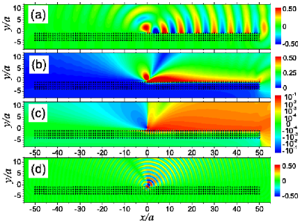
78.20.Ls, 42.70.Qs, 41.20.Jb, 42.82.EtAnyone who has looked at himself in a mirror expects a faithful image from a localized source. As is illustrated in Fig. 1(a – c), we find a very surprising result that when an oscillating line source is placed in front of a special mirror consisting of a uniformly spaced flat collection of ferrite rods (indicated by the black circles), the left half of the image disappeared near some particular frequency. We call this phenomenon “Yin-Yang” reflection (YYR), with “Yin” denoting the darkened region and “Yang” the brightened region. The physics behind this is related to the quantized Hall effect (QHE) and one-way magnetic surface plasmon band states.
Electric currents that circulate around the edge of the sample are believed to be responsible for the QHE. Because of the broken time reversal symmetry (TRS) caused by the external magnetic field, this current only goes in one direction. There has recently been much interest in exploring if related phenomena can occur with photons. Among others, a skew scattering effect involving electromagnetic (EM) waves was discussed by Rikken and coworkers x ; possible edge-like one-way waveguide from magnetic photonic crystal (MPC) bands with finite Chern numbers was discussed by Haldane and Raghu Haldane and Wang and coworkers Joan .
We have also been searching for similar phenomena involving EM waves chui . All QHE experiments deal with transmission. Because of the continuity of the electric and magnetic fields at the boundary, photonic states with giant circulations can be probed using reflection. States with the largest one way circulation are derived from the magnetic surface-plasmon (MSP) bands msp1 ; lw .
Plasmonic materials Ebsn ; sp ; konosky ; Maier ; abajo are capturing increasing interest due to their different promising applications. Most attention until now has been focused on the electric surface plasmons originating from the collective resonance of electronic density wave and hosted by metallic building blocks. The symmetry of Maxwell’s equations with respect to the magnetic and electric degrees of freedom enables a symmetric type of phenomenon in magnetic systems, which is known as a “magnetic surface plasmon” msp0 . When a periodic array of such material is assembled together, the photonic states that hop from one MSP state to another form a MSP band msp1 ; lw . In contrast to the electric surface plasmon band, the MSP band states only go in one direction (clockwise, for example), resulting from the breakdown of time reversal invariance caused by the finite magnetic field. The YYR effect comes from the coupling to states derived from these bands.
The YYR effect has the potential to revolutionize microwave circuitry. The diffraction limit requires that the minimum size of waveguides be larger than half the wavelength of light. Surface plasmons have attracted much attention as a way of circumventing the diffraction limit. We show below that the YYR can be exploited to build tunable subwavelength waveguides, beam benders and beam splitters. Furthermore, in these circuits, the EM wave exhibit a “superflow” behavior; the magnitude of the Poynting vector does not decrease in the presence of different kinds of defects. We next describe in detail our results, which are obtained using the rigorous multiple scattering method JOSA11 ; syliu .
For definiteness, consider a MPC consisting of a square lattice of parallel single crystal yttrium-iron-garnet (YIG) rods along direction in air separated by a distance . The radius of the YIG rod is . For single crystal YIG, the saturation magnetization gauss. The damping coefficient , and the permittivity , corresponding to a gyromagnetic linewidth of Oe and a dielectric loss tangent of , respectively Woh . We focus on the transverse magnetic (TM) wave with the electric field parallel to the rod axis.
Typical reflection behavior for mm is shown in Figs. 1(a) and 1(b), where the line source oscillating at a frequency of GHz is located away from a four-layer MPC slab. The applied external static magnetic field is such that the total field is 900 Oe, corresponding to a MSP resonance at GHz. The reflection is shaped such that the reflected wave is dramatically different on the left hand side (LHS) and the right hand side (RHS) of the source. On the LHS, the scattered field largely attenuates the incoming field near the interface. The MPC slab seems to repel the wave away from its surface, resulting in a shadowy region, called the “Yin” side. On the RHS, the scattered field instead significantly boosts the incoming field near the interface. The MPC slab seems to attract the wave to its surface, giving rise to a brightened region, or a “Yang” side, with an enhanced wave field. We next discuss the physics of the YYR.
Because of the broken TRS, the scattered field consists of unequal amount of states with opposite angular momenta and , resulting in a giant circulation. This unequal ratio is maintained as the sign of the wave vector is changed from to , so that the helicity of the circulation is unchanged. As a result, reflection from the LHS and the RHS of the source will be different. This difference is particularly dramatic only when the frequency is near the MSP resonance, where the angular momenta content is dominated by one sign, with the other sign almost completely suppressed leading to a very large circulation chui . Consequently, only energy flow in one direction is supported, while that in the other (opposite) direction is substantially suppressed near the MPC surface. Coupling to these states results in a brightened region on one side and a shadowy region on the other side. This is manifested in Fig. 1(c), where the component of the Poynting vector is exhibited. The rightward energy flow is sustained and reinforced, while the leftward energy flow is substantially suppressed, and eventually the system ends up with a YYR phenomenon. With this type of reflection, the EM wave is shaped to move mostly rightward near the interface. Wang and coworkers Joan recently demonstrated one-way waveguide effects based on the edge state of the MPC at a frequency regime away from the MSP. The asymmetry in the reflected field is not as significant, as is shown in Fig. 1(d). Aside from the variation due to the Bragg reflections, there is only a slight asymmetry in the field pattern near the MPC surface. This demonstrates the importance of the MSP resonance in enhancing the asymmetry of the reflection. We suspect that the MSP band states can also enhance the effect of possible edge state waveguides.
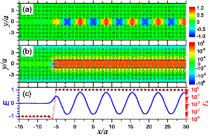
Now we turn to explore the possible applications of the YYR phenomenon. The first example is based on the remarkable asymmetry in the Poynting vector as shown in Fig. 1(c). Because there are band gaps both above and below the MSP resonance, the EM wave can be confined between two MPC slabs, similar to the conventional photonic crystal waveguide pcwg . If the magnetization of the two MPC slabs are in opposite directions, then the EM wave reflected forward from one MPC slab will also be reflected forward from the other MPC slab, leading to a different design of a one-way EM waveguide Haldane ; Joan ; yu , as is illustrated in Fig. 2(a). In Fig. 2, a line source is placed at between two MPC slabs apart. The parameters for the MPC slabs as well as the oscillating frequency of the line source are the same as in Fig. 1(a – c). It can be seen that the wave propagates rightward. Fig. 2(b) shows the component of the Poynting vector in a logarithmic scale. To further demonstrate the one-way transport characteristic, in Fig. 2(c) we display the electric field along and the rightward transmitted power, , as a function of . In addition, the EM flux exhibits an extremely low decay rate, the propagation loss is less than dB, using realistic material parameters for commercially available YIG ferrite Woh . To illustrate the physics, in the following, we shall neglect the damping.
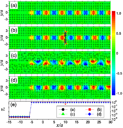
An important issue of current interest is the robustness of the energy flow against defects and disorder. One-way propagation based on the YYR appears immune to scattering from defects and disorders. Typical behavior are shown in Fig. 3(b – d). In Fig. 3(b) we show the electric field when a finite linear array of close-packed perfect electrical conductor (PEC) rods of radii are inserted into the channel from to , extending over . The wave circumvents the PEC defect, maintaining complete power transmission in the channel, with staying unchanged on the LHS and RHS of the defect, as shown in Fig. 3(e). The leftward propagating wave caused by the backscattering from the defect is completely suppressed, the wave gets around the defect and keeps moving rightward. By comparing with the waveguide shown in Fig. 3(a), it is found that the defect changes only the phase of the rightward propagating wave, partly owing to the delay incurred when it gets around the defect. In Fig. 3(c) and 3(d), we present the profile of the electric field for the cases when disorder in the positions and the radii of the YIG rods is introduced, respectively, in the MPC slab. The change in position is a random amount from zero to of the lattice spacing ; the random change in radius has a maximum of % of the unperturbed radius , small enough so that the disordered rods do not overlap. As can be seen, the disorder, either in position or in radius, only alters the wave form, but not the transmission power through the channel, implying the robustness against disorder, consistent with the fact that the MSP band states also exhibit finite Chern numbers. For the edge state waveguide Haldane ; Joan , the operating frequency lies in the Bragg band gap, so although their system is immune to scattering from the defect, it may suffer from disorder in either the position or the radius of the building blocks in the photonic crystals, as these effects will destroy the “Bragg” band gapmsp1 .
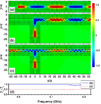
Photonic circuits with no back-scattering based on the YYR can be achieved even in the deep subwavelength regime. Figure 4 shows such examples where the geometry is scaled down in size with mm and , but the frequency GHz is unchanged. The other parameters are the same as those in Figs. 3(a). A subwavelength guide is shown in 4(a), with the full lateral width at half maximum field amplitude . In Fig. 4(b), the configuration is similar to that in Figs. 2 and 3 except that a cladding slab is added on top of the system. A line source is located at . The EM wave is found to make a turn with nearly power transmission in the proximity of the MSP resonance frequency, as shown by the blue solid line in Fig. 4(d). If one reverses the orientation of the magnetization for those rods with coordinates in the cladding slab, The propagation is seen to split at the bifurcation point, as shown in Fig. 4(c). The upward transmitted power, , is split with power transmission to the right and the other to the left by symmetry, as shown by the red dashed line in Fig. 4(d). The wave experiences an extremely low reflection at the corner , as can be seen from the field distribution before bending and splitting in the vertical channel. Furthermore, as the direction of the magnetization can be controlled by an external magnetic field, the function of the system can be switched between the function of bending and splitting.
In summary, we have demonstrated a new phenomenon, named ”Ying-Yang” reflection when the EM wave is reflected from a MPC. The phenomenon is believed to originate from the TRS breaking nature of the magnetic surface plasmon band states. Possible applications of this phenomenon include a one-way waveguide that appears to be immune to defect and disorder, sharp wave bending and beam splitting with extremely low reflection. These applications are expected to be realizable even in the deep subwavelength scale.
This work is supported by the China 973 program, NNSFC, PCSIRT, MOE of China (B08011), and Shanghai Science and Technology Commission. STC is partly supported by the DOE.
References
- (1) G. L. J. A. Rikken and B. A. Van Tiggelen, Nature 381, 54 (1996).
- (2) F. D. M. Haldane and S. Raghu, Phys. Rev. Lett. 100, 013904 (2008).
- (3) Z. Wang et al., Phys. Rev. Lett. 100, 013905 (2008).
- (4) S. T. Chui and Z. F. Lin, J. Phys. Condens. Matt. 19, 406233 (2007).
- (5) S. Y. Liu et al., Phys. Rev. B 78, 155101 (2008).
- (6) S. T. Chui and Z. F. Lin, Phys. Rev E 78, 065601(R) (2008).
- (7) W. L. Barnes, A. Dereux, and T. W. Ebbesen, Nature 424, 824 (2003).
- (8) A. V. Zayats, I. I. Smolyaninov, and A. A. Maradudin, Phys. Rep. 408, 131 (2005).
- (9) V. N. Konopsky, and E. V. Alieva, Phys. Rev. Letts. 97, 253904 (2006).
- (10) S. A. Maier, Plasmonics: Fundamentals and Applications (Springer, New York, 2007).
- (11) F. J. G. de Abajo, Rev. Mod. Phys. 79, 1267 (2007).
- (12) J. R. Gollub, et al. Phys. Rev. B 71, 195402 (2005).
- (13) D. Felbacq, G. Tayeb, and D. Maystre, J. Opt. Soc. Am. A 11, 2526 (1994).
- (14) D. M. Pozar, Microwave Engineering 3rd Ed. (Wiley, New York, 2005).
- (15) E. P. Wohfarth, in Ferromagnetic Materials (North-Holland, Amersterdam, 1986). Vol.2, p.293.
- (16) S. Y. Liu et al., Phys. Rev. Lett. 101, 157407 (2008).
- (17) H. C. van der Hulst, Light Scattering by Small Particles (Dover, New York, 1981).
- (18) A. Mekis et al., Phys. Rev. Lett. 77, 3787 (1996).
- (19) Z. Yu et al., Phys. Rev. Lett. 100, 023902 (2008).