Self-oscillations in a superconducting stripline resonator integrated with a DC-SQUID
Abstract
We study self-sustained oscillations (SO) in a Nb superconducting stripline resonators (SSR) integrated with a DC superconducting quantum interface devices (SQUID). We find that both the power threshold where these oscillations start and the oscillations frequency are periodic in the applied magnetic flux threading the SQUID loop. A theoretical model which attributes the SO to a thermal instability in the DC-SQUID yields a good agreement with the experimental results. This flux dependant nonlinearity may be used for quantum state reading of a qubit-SSR integrated device.
pacs:
74.40.+k, 02.50.Ey, 85.25.-jWe study thermal instability in superconducting stripline resonators (SSR’s) working at gigahertz frequencies. We have recently demonstrated how thermal instability can create extremely strong nonlinearity in such resonators Segev et al. (2007a, 2008). This nonlinearity is manifested by self-sustained oscillations (SO) at megahertz frequencies, strong intermodulation gain, stochastic resonance, sensitive radiation detection, and moreBachar et al. (2008). In the present work we have integrated a SSR with a DC superconducting quantum interface devices (SQUID). Similar configurations have been recently studied by other groups and it was shown that such devices can be used as readout and coupling elements for qubits Wallraff et al. (2004); Lupacu et al. (2006); Lee et al. (2007). In addition, it was shown that further improvement in the sensitivity of the readout process of the qubit is possible by biasing the resonator to a state of nonlinear responsitivity Siddiqi et al. (2006); Boaknin et al. (2007); Metcalfe et al. (2007); Lee et al. (2007); Lupacu et al. (2006).
Our experiments are performed using the setup depicted in Fig. 1. We study the response of the integrated SSR to a monochromatic injected pump tone that drives one of the resonance modes, and measure the reflected power spectrum by a spectrum analyzer. We find that there is a certain range in the plane of the pump-frequency pump-power parameters, in which intrinsic SO occur in the resonator. These oscillations are manifested by the appearance of sidebands in the reflected power spectrum. In addition, we apply bias magnetic flux through the DC-SQUID and find that both the threshold where these oscillations start and their frequency are periodic in the applied magnetic flux, having a periodicity of one flux quantum. We extend our theoretical model Segev et al. (2007a), which has originally considered SO and thermal instability in a SSR integrated with a single micro-bridge, to include this flux dependency and find a good agreement with the experimental results.
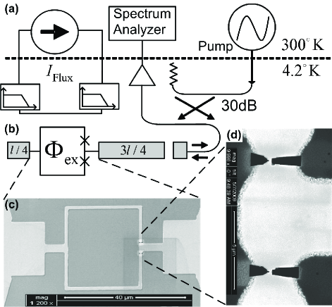
A simplified circuit layout of our device is illustrated in Fig. 1. We fabricate our devices on a Silicon wafer, covered by a thin layer of Silicon Nitride. Each device is made of a thin layer of Niobium and composed of a stripline resonator having a DC-SQUID (1 monolithically embedded into its structure. The resonator length is , and its first resonance mode is found at . The DC-SQUID has two nano-bridges (1, one in each of its two arms. Their size is typically and therefore each nano-bridge functions as a weak-link that approximately can be regarded as a regular Josephson junction Troeman et al. (2008a, b). A feed-line, weakly coupled to the resonator, is employed for delivering the input and output signals. An on-chip filtered DC bias line passing near the DC-SQUID is used to apply magnetic flux through the SQUID. Some measurements are carried out while the device is fully immersed in liquid Helium, while others in a dilution refrigerator where the device is in vacuum. Further design considerations and fabrication details can be found elsewhere Suchoi et al. (2009).
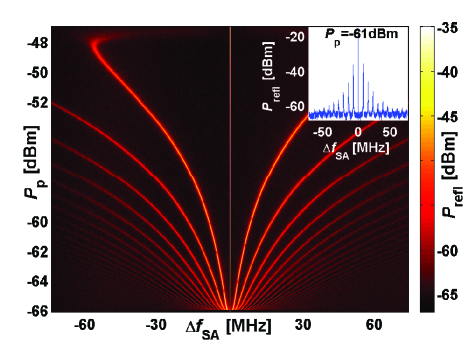
Figure 2 exhibits SO in the power reflected off the resonator Segev et al. (2007b, a). In this measurement we inject into the resonator an input pump tone having a monochromatic frequency , and measure the reflected power spectrum around while varying the input pump power . At relatively low and high pump powers the response of the resonator is linear, namely, the reflected power spectrum contains a single spectral component at the frequency of the stimulating pump tone. In between these two power thresholds the resonator self oscillates and regular modulation of the pump tone occurs. As a result, the reflected spectrum contains several orders of modulation products realized by rather strong and sharp sidebands (see inset of Fig. 2) that extend to both sides of the pump tone frequency. The SO frequency, defined as the frequency difference between the pump frequency and the primary sideband, ranges between few to tens of megahertz and increases with the pump power.
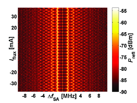
The dependence of the SO on the applied magnetic flux is shown in Fig. 3. In this measurement we inject a pump tone having a stationary frequency and power , and measure the reflected power spectrum around while varying the DC bias current. As shown, the SO frequency is periodically changed by the applied magnetic flux. The periodicity is one flux quantum and the relative change is typically about . Figures 4 and show two measurements of flux dependent SO obtained with pump power above and equal the threshold power , respectively. The later measurement demonstrates how magnetic flux can switch the resonator from a steady state response to a limit-cycle state where it experiences SO.
To account for our results we model our device as a transmission line resonator interrupted by a DC-SQUID. The impedance of the DC-SQUID is composed of a constant inductor in series with a flux-dependent inductor shunted by a parallel resistor Suchoi et al. (2009). The flux dependence of the DC-SQUID impedance gives rise to periodic dependence of the SSR’s damping rates on the applied magnetic field (the change in the SSR resonance frequency is relatively small).
The dynamics of our system can be captured thus by two coupled equations of motion Segev et al. (2007a). The first equation describes the dynamics of a resonator driven by feed-line carrying an incident coherent tone , where is constant complex amplitude and is the driving angular frequency. The mode amplitude inside the resonator can be written as , where is complex amplitude, which is assumed to vary slowly on a time scale of . In this approximation, assuming a noiseless system, the equation of motion of reads Yurke and Buks (2006)
| (1) |
where is the angular resonance frequency and , where is the coupling coefficient between the resonator and the feed-line and is the temperature and flux dependent damping rate of the mode.
The heat-balance equation for the temperature of the nano-bridges composing the DC-SQUID is given by Segev et al. (2007b)
| (2) |
where is the thermal heat capacity, is the heat transfer coefficient, and is the temperature of the coolant.
Coupling between Eqs. (1) and (2) originates by the dependence of the damping rate of the driven mode on the impedance of the DC-SQUID Saeedkia et al. (2005), which in turn depends on the temperature of its nano-bridges and on the applied magnetic flux. We assume a simple case, where the dependence on the temperature is described by a step function that occurs at the critical temperature of the superconductor. We further assume that only when the nano-bridges are in a superconducting phase the damping rate depends on the external flux. Namely, takes a flux dependent value when the nano-bridges are in a superconducting phase and a flux-independent value when they are is a normal-conducting phase .
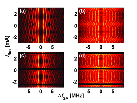
The results of a numerical integration of the equations of motion are shown in Fig. 4 and . Our model qualitatively reproduces the same flux dependency of the SM frequency on the magnetic flux. The parameters used for the numerical simulation were obtained as follows. The thermal heat capacity and the heat transfer coefficient were calculated analytically according to Refs. Johnson et al. (1996); Weiser et al. (1981). The values of the resonance frequency and the various damping rates, , , , and were extracted from S11 reflection coefficient measurements according to Arbel-Segev et al. (2006).
In conclusion, we report on periodic flux-dependency of SO in a SSR integrated with a DC-SQUID. The flux significantly modulates the oscillation frequency and can be used to turn them on and off if the device is driven near the power threshold. A theoretical model which attributes this behavior to thermal instability in the DC-SQUID exhibits a good quantitative agreement with the experimental results.
We thank Steve Shaw for valuable discussions and helpful comments. E.S. is supported by the Adams Fellowship Program of the Israel Academy of Sciences and Humanities. This work is supported by the German Israel Foundation under grant 1-2038.1114.07, the Israel Science Foundation under grant 1380021, the Deborah Foundation, the Poznanski Foundation, Russell Berrie nanotechnology institute, and MAFAT.
References
- Segev et al. (2007a) E. Segev, B. Abdo, O. Shtempluck, and E. Buks, J. Phys. Cond. Matt. 19, 096206 (2007a).
- Segev et al. (2008) E. Segev, B. Abdo, O. Shtempluck, and E. Buks, Phys. Rev. B 77, 012501 (2008).
- Bachar et al. (2008) G. Bachar, E. Segev, O. Shtempluck, S. W. Shaw, and E. Buks, arXiv p. 0810.0964v2 (2008).
- Wallraff et al. (2004) A. Wallraff, D. I. Schuster, A. Blais, L. Frunzio, R.-S. Huang, J. Majer, S. Kumar, S. M. Girvin, and R. J. Schoelkopf, Nature 431, 162 (2004).
- Lupacu et al. (2006) A. Lupacu, E. F. C. Driessen, L. Roschier, C. J. P. M. Harmans, and J. E. Mooij, Phys. Rev. Lett. 96, 127003 (2006).
- Lee et al. (2007) J. C. Lee, W. D. Oliver, K. K. Berggren, and T. P. Orlando, Phys. Rev. B 75, 144505 (2007).
- Siddiqi et al. (2006) I. Siddiqi, R. Vijay, M. Metcalfe, E. Boaknin, L. Frunzio, R. J. Schoelkopf, and M. H. Devoret, Phys. Rev. B 73, 054510 (2006).
- Boaknin et al. (2007) E. Boaknin, V. Manucharyan, S. Fissette, M. Metcalfe, L. Frunzio, R. V. I. Siddiqi, A. Wallraff, R. J. Schoelkopf, and M. Devoret (2007), , arXiv:cond-mat/0702445v1.
- Metcalfe et al. (2007) M. Metcalfe, E. Boaknin, V. Manucharyan, R. Vijay, I. Siddiqi, C. Rigetti, L. Frunzio, R. J. Schoelkopf, and M. H. Devoret, Phys. Rev. B 76, 174516 (2007).
- Troeman et al. (2008a) A. G. P. Troeman, S. H. W. V. der Ploeg, E. Il’Ichev, H.-G. Meyer, A. A. Golubov, M. Y. Kupriyanov, and H. Hilgenkamp, Phys. Rev. B 77, 024509 (2008a).
- Troeman et al. (2008b) A. G. P. Troeman, H. Derking, B. Borger, J. Pleikies, D. Veldhuis, and H. Hilgenkamp, Nano Lett. 7, 2152 (2008b).
- Suchoi et al. (2009) O. Suchoi, B. Abdo, E. Segev, O. Shtempluck, M. P. Blencowe, and E. Buks, arXiv 0901.3110v1 (2009).
- Segev et al. (2007b) E. Segev, B. Abdo, O. Shtempluck, and E. Buks, Europhys. Lett. 78, 57002 (2007b).
- Yurke and Buks (2006) B. Yurke and E. Buks, J. Lightwave Tech. 24, 5054 (2006).
- Saeedkia et al. (2005) D. Saeedkia, A. H. Majedi, S. Safavi-Naeini, and R. R. Mansour, IEEE Microwave Wireless Compon. Lett. 15, 510 (2005).
- Johnson et al. (1996) M. W. Johnson, A. M. Herr, and A. M. Kadin, J. Appl. Phys. 79, 7069 (1996).
- Weiser et al. (1981) K. Weiser, U. Strom, S. A. Wolf, and D. U. Gubser, J. Appl. Phys. 52, 4888 (1981).
- Arbel-Segev et al. (2006) E. Arbel-Segev, B. Abdo, O. Shtempluck, and E. Buks, IEEE Trans. Appl. Superconduct. 16, 1943 (2006).