eurm10 \checkfontmsam10
Generation and Breakup of Worthington Jets After Cavity Collapse.
Abstract
Helped by the careful analysis of their experimental data, Worthington & Cole (1897, 1900) described roughly the mechanism underlying the formation of high-speed jets ejected after the impact of an axisymmetric solid on a liquid-air interface. They made the fundamental observation that the intensity of these sharp jets was intimately related to the formation of an axisymmetric air cavity in the wake of the impactor. In this work we combine detailed boundary-integral simulations with analytical modeling to describe the formation and break-up of such Worthington jets in two common physical systems: the impact of a circular disc on a liquid surface and the release of air bubbles from an underwater nozzle. We first show that the jet base dynamics can be predicted for both systems using our earlier model in Gekle, Gordillo, van der Meer and Lohse. Phys. Rev. Lett. 102 (2009). Nevertheless, our main point here is to present a model which allows us to accurately predict the shape of the entire jet. In our model, the flow structure inside the jet is divided into three different regions: The axial acceleration region, where the radial momentum of the incoming liquid is converted into axial momentum, the ballistic region, where fluid particles experience no further acceleration and move constantly with the velocity obtained at the end of the acceleration region and the jet tip region where the jet eventually breaks into droplets. Good agreement with numerics and some experimental data is found. Moreover, we find that, contrarily to the capillary breakup of liquid cylinders in vacuum studied by Rayleigh (1878), the breakup of stretched liquid jets at high values of both Weber and Reynolds numbers is not triggered by the growth of perturbations coming from an external source of noise. Instead, the jet breaks up due to the capillary deceleration of the liquid at the tip which produces a corrugation to the jet shape. This perturbation, which is self-induced by the flow, will grow in time promoted by a capillary mechanism. Combining these three regions for the base, the jet, and the tip we are able to predict the exact shape evolution of Worthington jets ejected after the impact of a solid object - including the size of small droplets ejected from the tip due to a surface-tension driven instability - using as the single input parameters the minimum radius of the cavity and the flow field before the jet emerges.
1 Introduction
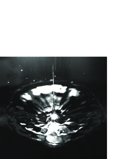
The impact of a solid object against a liquid interface is frequently accompanied by the ejection of a high speed jet emerging out of the liquid bulk into the air. Figure 1, which shows the effect of a horizontal disc that impacts on a pool of water, illustrates a liquid jet which flows times faster than the disc impact speed. The qualitative description of this common and striking phenomenon was firstly elucidated at the beginning of the twentieth century by Worthington & Cole (1897, 1900). Through the careful analysis of the photographs taken after a solid sphere was dropped into water, Worthington & Cole (1897, 1900) realized that these type of liquid threads emerge as a consequence of the hydrostatic collapse of the air-filled cavity which is created at the wake of the impacting solid. Worthington & Cole (1897, 1900) also made the remarkable observation that the generation of such cavities was very much influenced by the surface properties of the spherical solid. One century after their original observations, Duez et al. (2007) quantified the conditions that determine the existence of the air cavity in terms of the surface properties of the solid and the material properties of the liquid.
High speed jets emerging out of a liquid interface are also frequently observed in many other situations. For instance, it is very usual to perceive that the liquid “jumps” out of the surface of sparkling drinks, a fact which is known to happen as a consequence of bubbles bursting at the liquid interface [Boulton-Stone & Blake (1993); Duchemin et al. (2002); Liger-Belair et al. (2008)]. Similarly, the impact of a drop on a liquid interface or solid surface [Oguz & Prosperetti (1990); Shin & McMahon (1990); Rein (1993); Morton et al. (2000); Deng et al. (2007); Bartolo et al. (2006)], is commonly accompanied by the ejection of liquid jets whose velocities can be substantially larger than that of the impacting drop. Less familiar situations such as those related to the focussing of capillary [MacIntyre (1968); Thoroddsen et al. (2007b)] or Faraday waves [Hogrefe et al. (1998); Zeff et al. (2000)] also give rise to the same type of phenomenon. Nevertheless, in spite of the clear analogies, the main difference between the situations enumerated above and the case of jet formation after cavity collapse is that, in the latter case, surface tension does not play any role in the jet ejection process [see Gekle, Gordillo, van der Meer & Lohse (2009a) for details]. Indeed, the type of Worthington jets to be described here depend on a purely inertial mechanism, namely the radial energy focussing along the narrow cavity wall right before the cavity pinches-off. This fact makes our process also somewhat different from situations in which jets are induced by pressure waves [Ohl & Ikink (2003); Tjan & Phillips (2007); Antkowiak et al. (2007); Blake et al. (1993)].
Moreover, contrarily to what could be expected from the analogy with other related physical situations [Longuet-Higgins (1983); Longuet-Higgins & Oguz (1995)], Gekle et al. (2009a) pointed out that jets formed after cavity collapse are not significantly influenced by the hyperbolic type of flow existing at the pinch-off location. Instead, the description of this type of jets shares many similarities with the very violent jets of fluidized metal which are ejected after the explosion of lined cavities [e.g. Birkhoff et al. (1948)], with those formed when an axisymmetric bubble collapses inside a stagnant liquid pool [Manasseh et al. (1998); Bolanos-Jiménez et al. (2008)] or possibly even with the granular jets observed when an object impacts a fluidized granular material [Thoroddsen & Shen (2001); Lohse et al. (2004)].
Most of the results presented here refer to the perpendicular impact of a circular disc with radius and constant velocity against a liquid surface. The fact that the solid is a disc instead of a sphere leads to the formation of an air cavity which is attached at the disc periphery, independent of the surface properties. Thus, this choice for the solid geometry avoids the additional difficulty of determining the position of the void attachment line on the solid surface. The differences pointed out above set our system somewhat apart from similar studies [Duclaux et al. (2007); Glasheen & McMahon (1996)]. The experimental realization of the setup to which the numerical simulations presented are referred, is described by Bergmann et al. (2006, 2009); Gekle et al. (2008, 2009a), who show that boundary-integral simulations are in excellent agreement with experiments. In addition, potential flow numerical simulations to study of the type of Worthington jets ejected after bubble pinch-off from an underwater nozzle sticking into a quiescent pool of water [Manasseh et al. (1998); Longuet-Higgins et al. (1991); Oguz & Prosperetti (1993); Burton et al. (2005); Keim et al. (2006); Thoroddsen et al. (2007a, 2008); Gordillo et al. (2007); Burton & Taborek (2008); Gordillo (2008); Bolanos-Jiménez et al. (2008); Schmidt et al. (2009)] are also reported in this paper. As in the case of Worthington jets ejected after solid body impact, similar boundary-integral simulations have been shown to be in excellent agreement with experiments [see Oguz & Prosperetti (1993); Bolanos-Jiménez et al. (2008)].
2 Numerical methods
In this paper we have used three types of boundary-integral simulations. The first two model, respectively, the normal impact of a disc on a free surface and the pinch-off of a bubble from an underwater nozzle. With the purpose of simulating the capillary breakup of the jets formed in the first two situations, the third type of simulation represents a jet issued from a constant-diameter nozzle with an imposed axial strain rate. The latter type of numerical simulations have the advantage of allowing us to directly impose the values of both the strain rate and the Weber number, which are the parameters controlling the breakup of the jet, as will become clear from the discussion below.
2.1 Disc impact simulations
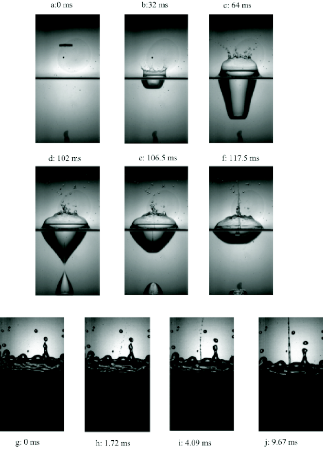
The process of disc impact [see also Bergmann et al. (2006, 2009); Gekle et al. (2009a)] is illustrated in figure 2: after impact a large cavity is created beneath the surface which subsequently collapses about halfway due to the hydrostatic pressure from the liquid bulk. From the closure location two high-speed jets are ejected up- and downwards. Here positions, velocities and time are made dimensionless using as characteristic quantities the disc radius , the impact velocity , and , respectively. (Variables in capital letters will be used to denote dimensional quantities whereas their lower case analogs will indicate the corresponding dimensionless variable). Moreover, it will be assumed that axisymmetry is preserved and, thus, a polar coordinate system will be used. The origins of both the axial polar coordinate and of time are set at the cavity pinch-off height and at the pinch-off instant, respectively.
Since global and local Reynolds numbers are large and the generation of vorticity is negligible [Bergmann et al. (2009); Gekle et al. (2009a)] we can make use of a flow potential to describe the liquid flow field. The numerical details, including the “surface surgery” needed to accurately capture the transition from the cavity collapse process to the jet ejection, are given elsewhere [see Gekle et al. (2009a); Bergmann et al. (2009)]. These simulations have shown excellent agreement with experimental high-speed recordings and particle image velocimetry measurements [Bergmann et al. (2006); Gekle et al. (2008, 2009a); Bergmann et al. (2009)]. The simulation stops when the downward jet hits the disc surface.
Since the Reynolds number is large, the dimensionless parameters controlling the jet ejection process are the Froude number, , and the Weber number, where , and indicate the gravitational acceleration, the liquid density and the interfacial tension, respectively. Since in all cases considered here, the jet ejection is not promoted by surface tension [Gekle et al. (2009a)]. Nonetheless, capillarity is essential to describe the jet breakup process, as will become clear from the discussion below. Air effects, which play an essential role during the latest stages of cavity collapse [Gordillo, Sevilla, Rodríguez-Rodríguez & Martínez-Bazán (2005); Gordillo (2008); Gekle, Peters, Gordillo, van der Meer & Lohse (2009b)], are not taken into explicit consideration here. Instead the cut-off radius at which the cavity geometry is changed into the jet geometry is fixed manually verifying carefully that the exact value of this parameter does not influence our results. The only consequence of this simplification is that a tiny fraction of the jet - the jet tip - may not be accurately described neither by our numerical simulations nor by our theory as will be discussed in section 3.1.
2.2 Bubble pinch-off from an underwater nozzle
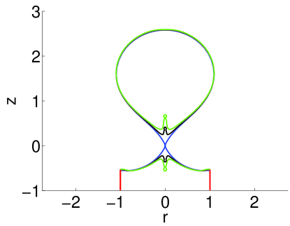
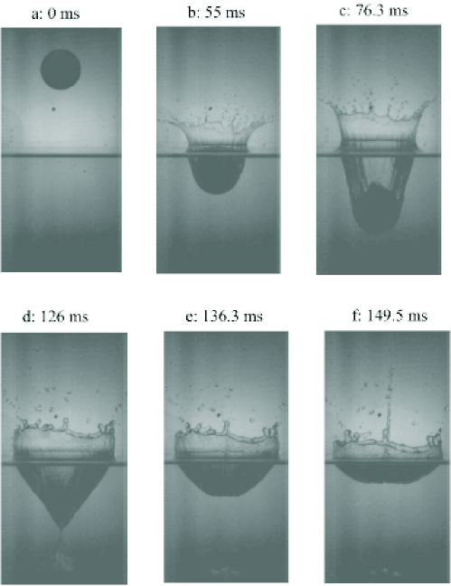
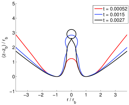
In the second type of simulations a bubble grows and detaches when a constant gas flow rate is injected from an underwater nozzle into a quiescent pool of liquid. Manasseh et al. (1998) and Bolanos-Jiménez et al. (2008) experimentally showed that this process also creates high speed jets. Indeed, as the bubble grows in size, the neck becomes more and more elongated and, eventually, surface tension triggers the pinch-off of the bubble, leading to the formation of two fast and small jets as illustrated in figure 3. Surface tension also leads to the pinch-off of a small droplet at the jet tip, which is precisely the instant when the simulation stops.
Here, distances are made non-dimensional using the nozzle radius as the characteristic length scale; moreover, the prescribed gas flow rate is used to derive the typical time scale . For the quasi-static injection conditions considered here, the relevant dimensionless parameter characterizing this physical situation is the Bond number [Longuet-Higgins et al. (1991); Bolanos-Jiménez et al. (2008)], which in the case presented here equals . More details of our simulation method are given in Oguz & Prosperetti (1993); Gekle et al. (2009c). Note that the present numerical simulations [Oguz & Prosperetti (1993)] as well as those reported using a very similar numerical method [Bolanos-Jiménez et al. (2008)], are in excellent agreement with experiments.
.
2.3 Simulations of a jet ejected at constant diameter
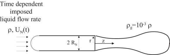
As will be shown by our theoretical analysis below, the jet breakup process can be described in terms of two dimensionless parameters evaluated nearby the base of the jet, namely, the local Weber number and the dimensionless axial strain rate. These quantities depend non-trivially on the input parameters of our physical simulations (disc speed, nozzle size etc.). In order to obtain a way of systematically varying both the local Weber number and strain rate we conducted a third type of simulation by adapting the axisymmetric (two-fluid) boundary integral method described in Gordillo et al. (2007) to a situation that retains the essential ingredients to describe the capillary breakup process in the first two types of simulations. For this purpose, we have simulated the discharge of a liquid injected through a constant radius needle with a length of 20 times its radius into a gaseous atmosphere. The density ratio of the inner and outer fluids is and a uniform velocity profile linearly decreasing with time is imposed on the boundary that delimits the computational domain on the left (see figure 4). Initially, the liquid interface is assumed to be a hemisphere attached at the nozzle tip. The uniform velocity with which the liquid is injected varies in time according to
| (1) |
with the dimensionless strain rate and the initial velocity determined by the physical situation which one intends to imitate (jets formed either after the disc impact or from the underwater nozzle). For these type of simulations positions, velocities and time will be made non dimensional using, as characteristic dimensional quantities, the injection needle radius , the initial velocity , and respectively.
In section 3.4 we demonstrate very good agreement between the results of these type of simulations and those related to the formation of jets after bubble pinch-off from an underwater nozzle. Unfortunately, the extremely large values of the Weber number reached at the tip of the liquid jets formed after the impact of a disc on a free surface () unavoidably lead to the development of numerical instabilities [Tjan & Phillips (2007)]. This fact makes a direct comparison between the simulations of the axial strain system sketched in figure 4 and those corresponding to the impacting disc impossible.
3 Analysis of numerical results
3.1 Effects of azimuthal asymmetries in the determination of the cut-off radius
The value of (the minimum radius of the cavity before the jet emerges) would be zero under the ideal conditions of our simulations, which do not take into account gas effects [Gordillo et al. (2005); Gordillo (2008); Gekle et al. (2009b); Burton & Taborek (2008)], liquid viscosity [Burton et al. (2005); Thoroddsen et al. (2007a); Bolanos-Jiménez et al. (2009)] or small azimuthal asymmetries that may be present in the flow [Keim et al. (2006); Schmidt et al. (2009)]. This would imply that the initial jet velocity would be infinity. However, all the effects enumerated above are known to strongly influence the spatial region surrounding the cavity neck during the very last stages of bubble pinch-off and, therefore, are essential to determine the real value of (Gordillo (2008); Gekle et al. (2009b)).
Note first that, the larger is, the smaller will be the maximum liquid velocity at the tip of the jet.
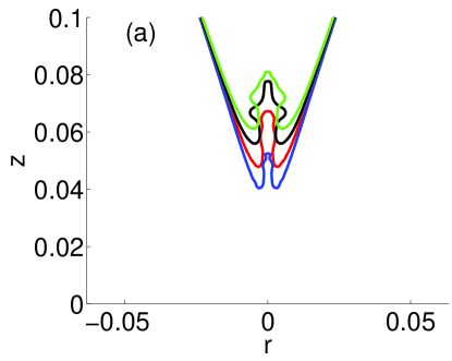
Here we will provide experimental evidence showing that non-axisymmetric perturbations are of crucial importance to fix and, consequently, the maximum velocity reached by the jet. This is due to the fact that asymmetries influence the radial flow focussing effect on the central axis even before the actual cavity closure. The development of azimuthal instabilities leads to a decrease of the liquid acceleration towards the axis before pinch-off and thus reduces the speed of the ejected jet. This is clearly observed in figures 5 and 6, which show the cavity formation and jet ejection processes when either a brass disc (smooth surface) or a golf ball (structured surface) impact perpendicularly on a quiescent pool of water. Despite the fact that both the velocity and the diameter of the ball are larger than those of the disc, the maximum jet velocity is larger for the disc case. Indeed, while the shape of the cavity in figure 5 is smooth, the cavity interface in figure 6 clearly exhibits asymmetric modulations already right after the impact (which – in addition to the rough surface structure – may in part also be due to a rotation of the ball). Note that the overall shape of the cavity is very similar in both cases. Consequently, since the self-acceleration of the liquid towards the axis is lost when the amplitude of azimuthal disturbances is similar to the radius of the cavity, the maximum velocity reached during the collapse process decreases when the cavity interface is not smooth. Note that figures 5 and 6 are representative of an exhaustive set of experiments. The analysis of the whole experimental data has shown that the rough surface systematically produces lower jet speeds.
The initial amplitude or the precise instant at which such azimuthal instabilities may develop is not easy to predict. For instance, Keim et al. (2006); Schmidt et al. (2009) pointed out that tiny geometrical asymmetries in the initial setup might break the cylindrical symmetry of the cavity at the pinch-off location. Moreover, even if the cavity is perfectly axisymmetric, the strong shear between the gas and the liquid will induce instabilities that tend to break the cylindrical symmetry of the cavity [Leppinen & Lister (2003); Bergmann et al. (2006)].
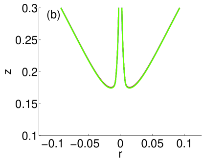
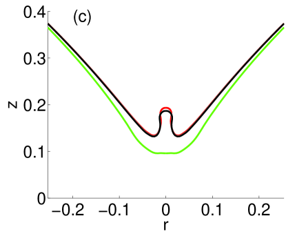
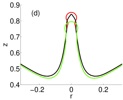
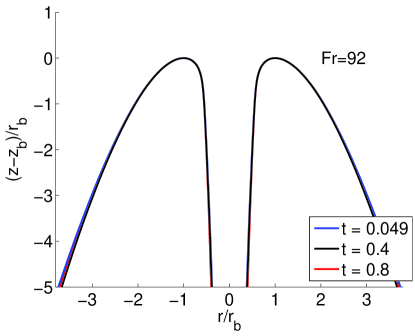
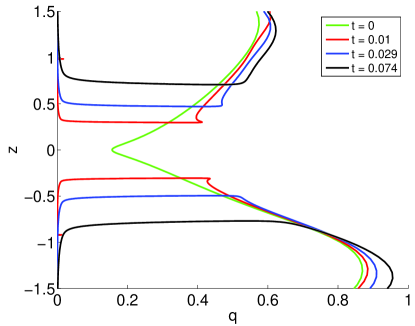
Therefore, the precise determination of is a very complex and difficult subject which in addition will heavily depend on the system under study and must therefore remain outside the scope of this contribution. We have instead decided to vary within reasonable bounds and to analyze carefully the effect on the subsequent time evolution of the jet. It can be clearly appreciated in figure 7 that differences in the simulations can be observed in both the jet base and tip region right after pinch-off occurs. However, as soon as the jet radius at its base becomes of the order of the maximum value of explored, differences in the jet base region disappear and only remain appreciable in the jet tip region. Physically, this means that gas effects and small asymmetries will only be felt at the highest part of the jet, which represents only a very small fraction of both the total volume and of the total kinetic energy of the jet. Note also that, in spite of the jet tip being the spatial region where the highest velocities are reached, it is also the least reproducible one from an experimental point of view since it strongly depends on the precise details of pinch-off. Thus, regarding experimental reproducibility, our study will be valid to accurately describe the most robust part of the jet. In the case of the impacting disc we will set and in the case of the gas injection needle, the minimum radius will be fixed to .
Finally, note that our axisymmetric approach has been proven to be in excellent agreement with experiments whenever either the radius of the collapsing cavity or the radius of the emerging jet, are larger than the cut-off radius for which any of the effects enumerated above – gas, azimuthal perturbations – become relevant [see, for instance, Bergmann et al. (2006); Gekle et al. (2008); Bolanos-Jiménez et al. (2008); Gekle et al. (2009a); Bolanos-Jiménez et al. (2009)].
3.2 Jet ejection process for the disc impact
The different stages of the jet formation process have been illustrated in figure 2. After the solid body impacts against the free surface, an air cavity is generated (a). As a consequence of the favorable pressure gradient existing from the bulk of the liquid to the cavity interface, the liquid is accelerated inwards (b). These radially inward velocities focus the liquid towards the axis of symmetry, leading to the formation of two fast and sharp fluid jets shooting up- and downwards, as depicted in figure 2 (c). Here we will mainly focus on the detailed description of the upwards jet and demonstrate that the downward jet can be treated in the same way.
From figure 2, observe that larger Froude numbers create more slender cavities and also increase the non-dimensional depth at which the cavity pinches-off. Furthermore, it can be appreciated that the jets are extremely thin and that the time needed for the tip of the jet to reach the free surface is only a small fraction of the pinch-off time. This latter observation means that the jets possess a much faster velocity than the velocity of the impacting solid, a conclusion which was also extracted from the analysis of the experiments in figures 5-6. Motivated by this striking fact, one of the main objectives in this paper will be to address the following question: what is the relationship between the impact velocity - or, in dimensionless terms, between the Froude number - and the liquid velocity within the jet?
With this purpose in mind, it will prove convenient to define first the length scale that characterizes the jet width. In Gekle et al. (2009a) we showed that the time evolution of the jet is a local phenomenon, independent of the stagnation-point type of flow generated after pinch-off at the location where the cavity collapses. Therefore, this characteristic length needs to be related to a local instead of a global quantity and, following Gekle et al. (2009a), we choose the radial position at which the interface possesses a local minimum i.e., the radius indicated in figure 8. We shall in the following call this point the jet base and denote its vertical position by .
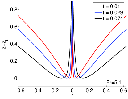
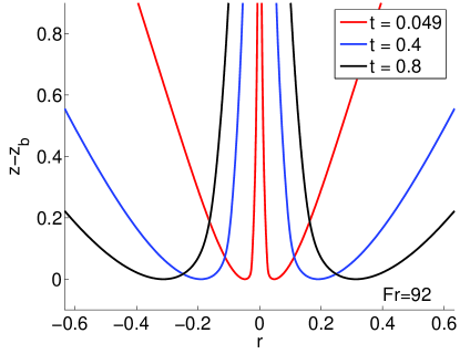
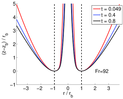
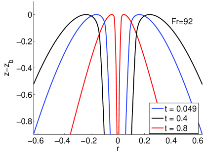
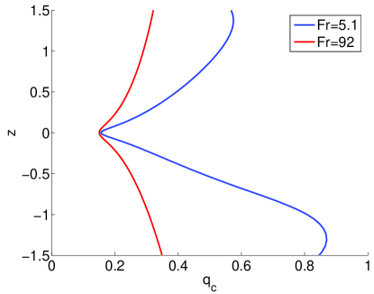
To clearly show the spatial region surrounding the jet base, some of the different jet shapes taken from the time evolutions of figure 2, are translated vertically so that they share a common vertical origin, as depicted in figure 9. Note that both the jet base and the jet itself widen as the time from pinch-off increases. Interestingly enough, figure 10 shows that jet shapes exhibit some degree of self-similarity since they nearly collapse onto the same curve when distances are normalized using . This fact indicates that is not an arbitrary choice, but a relevant local length that plays a key role in the dynamics of the jet. The same arguments hold for the downward jet as illustrated in figure 11.
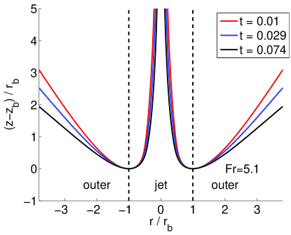
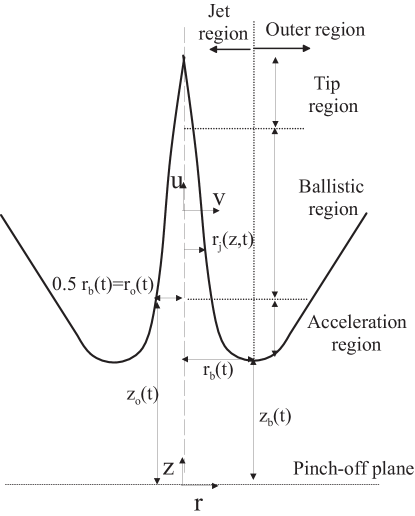
In order to model the full process of jet ejection and break-up we divide the liquid flow field into two different regions: the outer region, defined for , and the jet region, extending from the jet base to the axis i.e, and , as illustrated in figure 10. The jet region is further divided into three different axial subregions: the acceleration region, the ballistic region and the tip region as illustrated in figure 8.
Figure 12 shows that . These comparatively large values of with respect to are caused by the confinement of the jet by the cavity walls, which inhibits the widening of the base radius. Moreover, the small values of are responsible for the large axial velocities within the jet (and, thus, for the large values of ) since, as it will become clear below, vertical velocities are inversely proportional to .
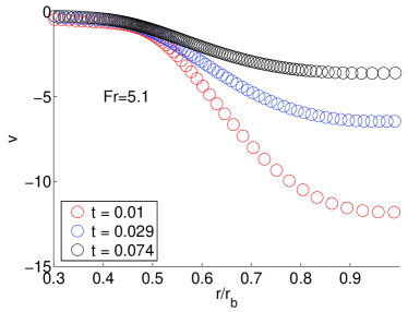
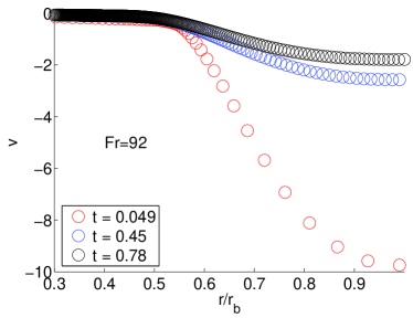
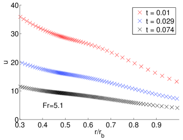
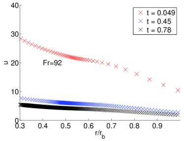
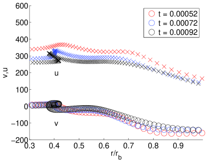
The importance of local processes around the jet base is even more clearly illustrated in figure 13 where both the axial and radial velocities evaluated at the jet air/liquid interface, and respectively, are represented for different instants of time. In this figure one can observe that while the axial velocities are of similar magnitude as the radial velocities at , they monotonically increase to much higher values as the jet radius diminishes. Contrarily, the modulus of the (negative) radial velocities decays from at to zero at and, therefore, the radial inflow experiences a strong deceleration in the small distance . Since the liquid is at atmospheric pressure at the free surface of the jet, the strong radial deceleration provokes an overpressure below the jet base. Accordingly, a strong favorable vertical pressure gradient is created and, therefore, the liquid experiences a large upwards acceleration in the vertical direction, creating the high speed jet ejected into the atmosphere.
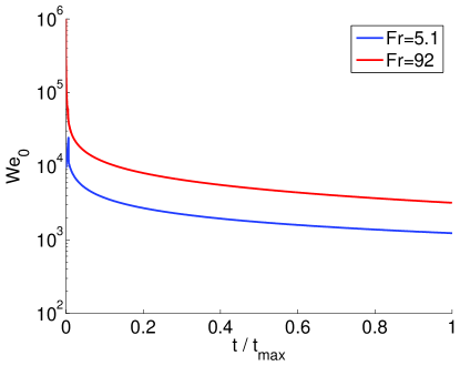
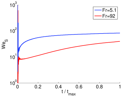
In the following, we shall define as the radial position on the jet interface at which radial velocities become negligible - for jet radii smaller than - and the corresponding vertical position and velocity, will be denoted in what follows and , respectively. Moreover, we will also define at this point a local Weber number as whose time evolution is depicted in figure 14. The large values indicate that surface tension effects can be neglected in the description of the jet ejection process.
Thus, since the jet interface can be considered to be at constant atmospheric pressure and surface tension effects are negligible near the jet base, the only source of axial acceleration is the axial pressure gradient caused by the radial deceleration of the flow. Remarkably, this radial deceleration takes place in a very localized region nearby the jet base. (For radial positions on the jet smaller than already as shown in figure 13.) Therefore, the source of axial acceleration (radial deceleration) is no longer active high up into the jet, but only near the jet base. This key observation is used to define two of the three different regions within the jet: the axial acceleration region for and and the ballistic region for , . The term used to name the latter region is based on the fact that, since for and the pressure at the jet interface is atmospheric, the momentum equation projected in the axial direction yields
| (2) |
and indicating the material derivative. Equation (2) implies that fluid particles are no longer accelerated upwards and conserve the vertical velocities they possess at , which is the axial boundary between the axial acceleration region and the ballistic region. In equation (2), since the radial velocity gradients of axial velocities are negligible in the ballistic region (not shown).
As a next step, we would like to scale the radial velocity field in the vicinity of the jet base which is, as discussed above, the source of momentum driving the jet ejection process. These radially inward velocities are originally created by the difference between the hydrostatic pressure in the bulk of the liquid and the gas pressure inside the cavity. After pinch-off however, the radial velocity field feeding the liquid jet is not appreciably modified by gravity during the time evolution of the jet since the local Froude number at the beginning of the ballistic region is with the axial distance between the beginning of the ballistic region and the height of the free surface far from the impact region (see figure 2).
Therefore, the radial velocities which give rise to the jet emergence can be characterized by the sink strength distribution at right before pinch-off occurs: , where and indicate the radius of the cavity and its associated radial velocity, respectively (see Gekle et al. (2009a)). The values of are shown in figure 15 for several values of the impact Froude number.
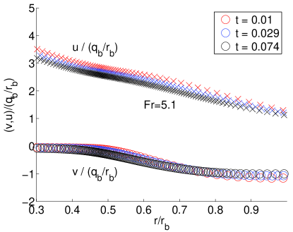
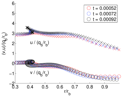
In order to demonstrate the intimate relation of the jet ejection process with the velocity field right before pinch-off, we normalize the velocities and at the jet surface (as shown in figure 13) using, as the characteristic scale for velocities, , where is the sink strength at the height of the jet base. The remarkable result, depicted in figure 16, is that both rescaled velocities nearly collapse onto the same master curves for a given Froude number and thus are almost constant in time for a fixed value of the rescaled position . This implies that, for a fixed value of , axial velocities are inversely proportional to i.e., the smaller the jet base radius - or, equivalently, the more confined is the jet by the cavity walls -, the larger will be the axial liquid velocities within the jet.
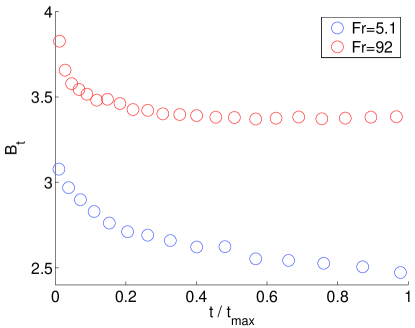
Of critical importance for our forthcoming discussion is the rescaled axial velocity evaluated at the boundary of the ballistic region, , whose time evolution is depicted in figure 17 (a). In accordance with the collapse of the rescaled velocities on a single master curve depicted in figure 16, hardly changes with time and, thus, we can define the function which depends also very weakly on the Froude number, as depicted in figure 17 (b).
The result in figure 17 possesses the additional remarkable implication that axial velocities within the jet are larger than the radial velocities existing at the cavity interface before pinch-off occurs. This can be seen directly by recalling that , such that is the ratio between the axial velocity with which fluid is ejected into the jet and the radial inward velocity at the jet base. Then, during the initial instants of jet formation, , with the minimum radius of the cavity before jet emerges. Therefore, since the maximum radial velocity before pinch-off occurs is , the maximum axial velocity within the jet is given by . This means that, essentially, the velocity with which the jet is ejected is roughly three times larger than the maximum radial velocity attained before pinch-off!
In addition, provided that , fluid particles conserve their axial velocity within the ballistic region [see equation (2)] and, consequently, the tip of the jet transports away from the pinch-off location very valuable information about the largest velocities reached during the cavity collapse process. The knowledge of the function could thus allow an experimentalist to estimate the maximal pinch-off velocity simply from measurements of the jet tip velocity.
3.3 Jet ejection after bubble pinch-off from an underwater nozzle
This section is devoted to the study of Worthington jets which are ejected after the bubble collapse into a liquid pool [Manasseh et al. (1998); Bolanos-Jiménez et al. (2008)]. As depicted in figure 3, these jets are quite similar to the ones formed after the impact of a solid body against a free surface and, thus, we expect that the conclusions of section 3.2 can be also used for their description.
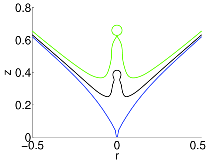
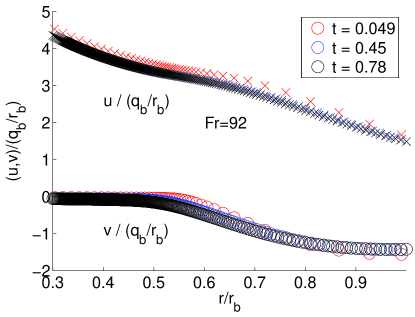
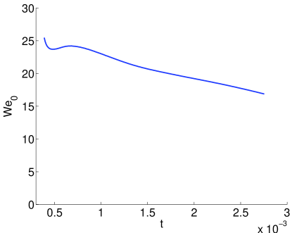
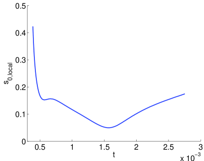
Figure 18 shows that, similarly to section 3.2, the different shapes nearly collapse onto the same master curve when distances are normalized using . This fact corroborates that is also the correct length scale to characterize this type of jets. However, differently to the case of Worthington jets ejected after the impact of a solid body against a free surface, in which , the local Weber number evaluated at the beginning of the ballistic region is in this case (see figure 19a). As a consequence of this, the total length at breakup of these jets is (see figure 18), i.e, much shorter than the length of the Worthington jets in section 3.2. Moreover, such comparatively low values of the local Weber number indicate that surface tension has an effect in the description of the jet ballistic region. This is clearly appreciated in figures 18 and 20 where the collapse onto each other of the normalized time evolutions of the axial and radial velocity components evaluated at the free surface ( and ) is also a bit deteriorated when compared with the case depicted in figure 16. Nevertheless, the two main prerequisites for the model to be presented in the following sections are also satisfied in this case: firstly, the acceleration and ballistic regions are clearly differentiated in figure 20 and, secondly, the normalization of the interfacial velocities with leads to a reasonable collapse onto a single master curve (see figure 20).
3.4 Jet breakup
The growth of capillary perturbations in a cylindrical liquid jet, firstly quantified by Rayleigh (1878) [see also Eggers & Villermaux (2008)], is based on the assumption that fluid particles conserve, to first order, their longitudinal velocity . Rayleigh’s analysis shows that, moving in a frame of reference with the jet velocity (which in his case is constant ), and no matter how large the Weber number is, the jet breaks due to the growth of capillary perturbations of wavelengths larger than the jet perimeter. The characteristic time needed for such perturbations to disrupt the jet into drops is the capillary time, , with the jet radius. Therefore the jet breakup length, , is such that if aerodynamic effects are absent [Sterling & Sleicher (1975); Gordillo & Pérez-Saborid (2005)]. Notice that the study of jet breakup in our case is somewhat related to that considered by Rayleigh since the fluid particles conserve their velocities, in a first approach, along the ballistic region of the jet.
Similarly to the case considered by Rayleigh (1878), the study of the capillary breakup of stretched jets will be divided in two: the calculation of the basic flow, which is free of capillary effects and the analysis of capillary waves propagating and growing in amplitude at the jet tip region. Viscous effects will be neglected in the analysis.
3.4.1 Unperturbed flow
If , the time evolution of both the jet radius and the liquid velocities in the ballistic region can be calculated neglecting surface tension forces and making use of the slenderness of the jet. However, differently to the case considered by Rayleigh (1878), in which the jet radius and , here and are functions of and . In effect, if the fluid is assumed to follow a purely vertical motion inside the ballistic region, the couple of equations that determine and are the momentum equation (2), which can be also written as
| (3) |
and the unidirectional version of the continuity equation, namely,
| (4) |
where indicates again the material derivative. From equations (3)-(4), , and - the height at which the jet radius is - are completely determined if the relevant quantities at the beginning of the ballistic region (, , and the velocity ) are known functions of time. Indeed, equation (3) expresses that fluid particles conserve the vertical velocity they possess at the beginning of the ballistic region. Consequently, a particle ejected from the acceleration into the ballistic region at time will, at time , have attained a height
| (5) |
To obtain the corresponding jet radius , equation (4) can be readily integrated to give
| (6) |
Introducing the definition of the strain rate at the beginning of the ballistic region
| (7) |
allows us to rewrite equation (6) in a more compact form as
| (8) |
Note that Rayleigh’s original analysis, and (cylindrical jet) may be recovered from equations (3)-(4) by setting and , and constants in time. However, in our case, and and, therefore, by virtue of equation (7), these conditions imply ; consequently, from equation (8), the jet is not cylindrical since it stretches downstream.
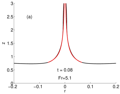
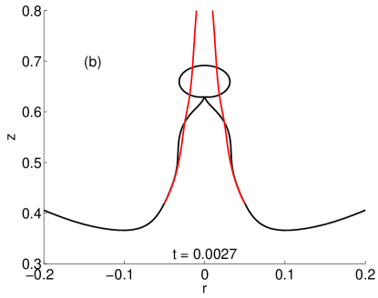
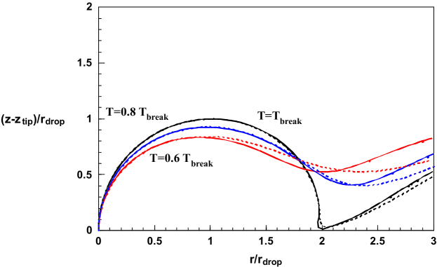
Now, in order to obtain the complete jet shape at time , we vary between 0 and and use equations (5) and (6) to compute the corresponding vertical and radial coordinates of the jet. Note that, clearly, the particle ejected at will end up forming the tip of the jet. The comparison between the numerical results and those obtained from the integration of (3)-(4), with the values of , and taken from the numerical simulations, is depicted in figure 21. The excellent agreement between numerics and the model validates the approach of considering that fluid particles conserve their axial velocities within the ballistic region. It should be pointed out, however, that equations (3)-(4) need to be corrected at the tip of the jet, where surface tension effects need to be retained.
3.4.2 Growth of capillary disturbances
The linear stability analysis for the type of velocity field given in section 3.4.1 was firstly accomplished by Frankel & Weihs (1985), who recovered Rayleigh’s original result in the limit of . It is our purpose here to extend the analysis on the breakup of stretched jets of Frankel & Weihs (1985) to account for non linear effects and also for the influence of the tip. It is worthy to mention that, in our numerical approach, the wavelength of fastest growth rate is naturally selected by the local flow around the jet tip and, therefore, a linear stability analysis of the type reported in Frankel & Weihs (1985), is avoided.
As a first step, the dimensional counterparts of [] and [] are chosen as the characteristic scales for lengths and velocities, respectively. Consequently, dimensional analysis indicates that the evolution of capillary perturbations in the ballistic region for will solely depend on the dimensionless parameters and .
The values of and depend non-trivially on the dimensionless parameters controlling the two different physical situations analyzed here. Consequently, in order to study systematically the jet breakup process as a function of and we employ the third type of simulations of the axial strain type described in section 2 and illustrated in figure 4. The real jet breakup process can then be reproduced provided that the values of the Weber number and the strain rate at the nozzle exit coincide with those at the beginning of the ballistic region i.e, and .
Note that, since the values of the Weber number based on and are always such that , the gas dynamics can be neglected and the only two relevant dimensionless parameters characterizing the axial strain system of figure 4 are and .
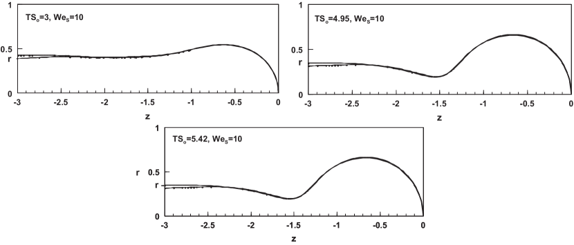
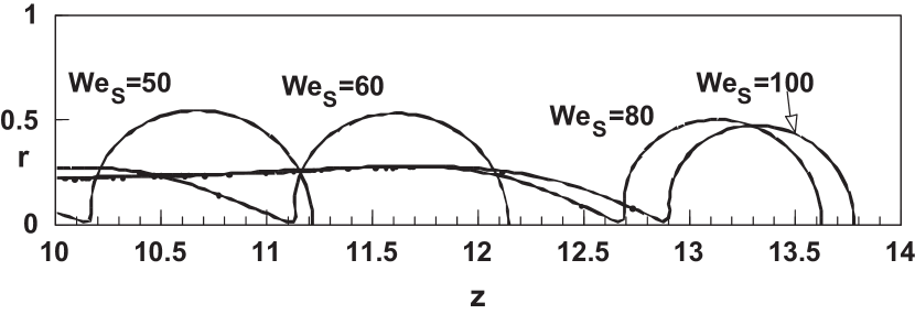
The numerical results depicted in figure 22 show a slender liquid thread which breaks many diameters downstream the nozzle exit. Moreover, it can be observed that the effect of increasing the Weber number is to increase the breakup time and the breakup length. Figure 23 shows a comparison between the shapes of the jets formed after bubble collapse depicted in figure 18 and those obtained from the simulations of the type illustrated in figure 22 with and . The excellent agreement between both type of numerical results corroborates the fact that tip breakup of Worthington jets can be reproduced by means of the simulations considered in this section if the values of the parameter and coincide with the initial values of and .
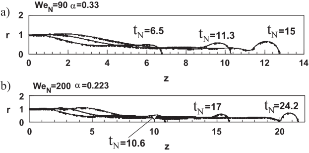
However, the numerical code used in this section is unstable for . Consequently, the third type of simulations cannot reproduce, at first sight, the breakup of jets ejected by an impacting disc since, in this case, as depicted in figure 14. Thus, is it nevertheless possible to describe the breakup process of jets with such high values of using the numerical simulations of the axial strain type illustrated in figure 4? The answer to this question is affirmative if we realize that, in a frame of reference moving at the tip velocity, the parametrical dependence on the velocity disappears. Consequently, since both the local flow field and the jet radius still depends in this frame of reference on (see equation (7)), dimensional analysis indicates that jet breakup can be described in terms of the dimensionless variables (or, analogously, ) and (or, analogously, ).
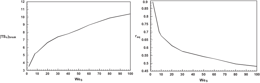
To check this, the results depicted in figure 22, which correspond to different values of and but to the same value of , are represented in figure 24. Remarkably, the different jet shapes superimpose onto each other for the same values of the dimensionless time , what indicates that the breakup process depends solely on (or, equivalently, on ) and on the dimensionless time (or, equivalently, on ) for sufficiently large values of . Figure 25 illustrates that the volume of the nearly spherical drops formed at breakup, decreases for increasing values of . In figure 25 note also that the range of values of investigated is realistic even for the impacting disc, as depicted in 26. Consequently, even though in some situations such as the disc may be very high, the important parameter which is can be matched to the simulations in this section. The dimensionless breakup time and the dimensionless size of the drops in figure 27 behave as and , respectively. A detailed corresponding theory will be the subject of a forthcoming contribution [Gordillo (2009)]. We emphasize that figure 27 describes a universal relation for the breakup of Worthington jets at high Weber numbers which allows one to obtain the breakup time and volume of the first ejected droplet knowing merely the value of defined at the beginning of jet formation.
Finally, note that, in order for , the computations have been performed choosing and, correspondingly, . The condition is essential since, if was not sufficiently large, the jet breakup process of real Worthington jets would depend on the liquid velocity and, thus, on and separately.
4 Modeling the jet ejection and breakup processes
Here we aim to develop a model to explain, in simple terms, the jet ejection and breakup processes. Our model will be based on the main conclusions of the previous section which are: (i) both and are local quantities which, therefore, do not depend on the large scales of the flow, (ii) the velocity field within the jet can be characterized solely in terms of the sink strength intensity at pinch-off, and (iii) the flow field within the jet can be divided in three parts: the acceleration region, the ballistic region and the jet tip region.
This section is structured as follows: in subsection 4.1 and are calculated in terms of only using the theory developed in Gekle et al. (2009a). Then, in section 4.2 the axial velocity and the jet shape within the ballistic portion of the jet are calculated through equations (3)-(4) using, as initial conditions, , and .
4.1 Reviewing the model for and
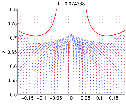
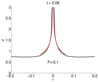
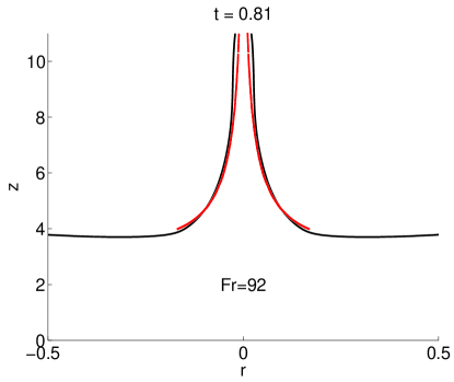
In this subsection we will very briefly review our model for jet formation as presented in Gekle et al. (2009a) and show its applications to predict the flow fields as well as the dynamics of the jet base for the impacting disc at Fr=5.1 and Fr=92 and the Worthington jets created after bubble pinch-off from an underwater nozzle.
The starting point of our model is the description of the cavity collapse using a line of sinks on the axis of symmetry as depicted in figure 15. After pinch-off most of this distribution remains intact with two notable exceptions: a hole is created between the bases of the up- and downward jet and sinks accumulate around the jet base [Gekle et al. (2009a)]. These effects are illustrated in figure 28. Based on this observation we derived in Gekle et al. (2009a) an analytical expression for the flow potential at an arbitrary point in the outer region (note that by construction the model is not valid inside the jet itself):
| (9) |
with the order one constants and chosen appropriately.
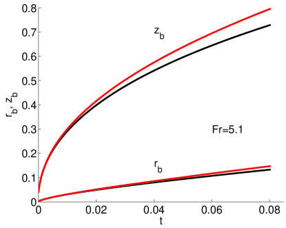
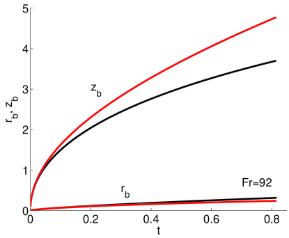
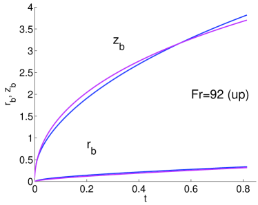
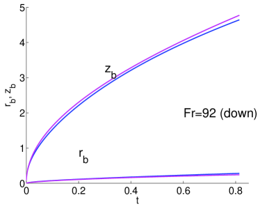
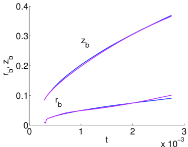
As shown in Gekle et al. (2009a) this model can be used to predict the temporal evolution of the jet base, i.e. the widening and upwards motion of the jet base. Here we will restrict ourselves to show the result of this procedure for the different systems studied in this work, which are depicted in figure 29.
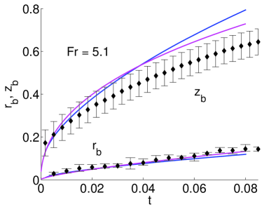
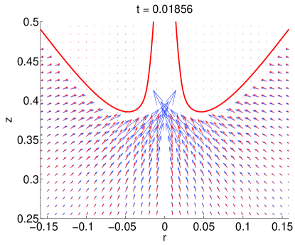
In fact, as shown in figure 30, equation (9) can also be used to predict the entire flow field in the outer region. Figures 29-30 illustrate the rather good agreement between theory and numerics, which we find in all cases studied.
4.2 Modeling the jet breakup and drop ejection processes
We will now take the model of the previous section one step further by combining its results with the analysis described in section 3.4.1. This will allow us to predict not only the flow field in the outer region, but also the flow inside the jet and thus the jet shape as a function of time.
Once and are obtained through the model in section 4.1, the axial velocity at the beginning of the ballistic region can be calculated as a function of known quantities as , with the function depicted in figure 17. Therefore, both the flow field and the jet shape within the ballistic region can be computed from the integration of equations (3)-(4) using, as initial conditions, , and . The comparison between the jet shape calculated numerically and that obtained from the model is depicted in figure 31 and good agreement is found.
The capillary breakup process of the jet can be also modeled making use of our numerical results in section 3.4.2 since, through equation (7), both and can be easily expressed as a function of , and , with the latter two functions given by the model as described above. Consequently, both the ejection and breakup process of the jet can be modeled with the only inputs of and , i.e. quantities defined before pinch-off.
Moreover, the trajectory of the ejected drops can also be modeled using the results of the previous sections. Indeed, the nearly spherical drops ejected from the tip of the jet follow a ballistic trajectory which can be calculated from Newton’s second law as
| (10) |
with and indicating the drop velocity and the drag coefficient, respectively. The drag term needs to be included since the relative variation of the drop velocity associated to aerodynamic effects, , can be estimated from equation (10), yielding
| (11) |
with the flight time of the drop. Therefore, since and , the relative variation of drop velocity associated to aerodynamic forces is given by
| (12) |
It needs to be pointed out that the validity of equation (10) rests on the assumption that drops conserve their spherical shape along their trajectory and, thus, are not atomized due to aerodynamic effects. This will be the case whenever the aerodynamic Weber number [Hanson et al. (1963); Villermaux (2007, 2009)]. Therefore, except for the very initial instants after cavity pinch-off, in which the gas Weber number could be larger than 6 - as can be inferred from figure 14 -, equation (10) is valid to calculate the drop velocity.
We are now able to calculate the trajectories of the drops ejected from the jet tip. Indeed, once the constants and of the jet base model in section 4.1 are properly chosen, they determine the values of and , which are the only inputs for the model and simulations described in section 3.4. With this knowledge, the numerical results of the type illustrated in figures 25 and 27 (which only depend on and ) allow one to calculate the size, velocity and ejection time of the first ejected droplet, the only inputs needed for the integration of equation 10.
5 Conclusions
Using detailed boundary-integral simulations together with analytical modeling, we have studied the formation and breakup of the high-speed Worthington jets ejected either after the impact of a solid object on a liquid surface or after the pinch-off of a gas bubble from an underwater nozzle. To describe the phenomenon as a whole we divided the flow structure in two parts separated by the jet base (, ): the outer region for , and the jet region, extending from the jet base to the axis i.e, and . The jet region is further subdivided into the three subregions: The axial acceleration region, where the radial inflow induced by the cavity collapse is decelerated radially and accelerated axially, the ballistic region, where fluid particles are no longer accelerated vertically and, thus, conserve the axial momentum they possess at the end of the acceleration region and the jet tip region, which is where the jet breakup process occurs.
We first show that the flow in the outer region is well described by the analytical model presented in Gekle et al. (2009a). This model further provides a set of equations for the time evolution of the jet base and . As depicted in figures 29 and 30, the analytical predictions are in remarkable agreement with numerical simulations for the up- and downwards jets of the disc impact as well as the upwards jet created after the bubble pinch-off from an underwater nozzle. The model uses as its only input parameters the minimum radius of the cavity and the sink strength , both taken at the moment of pinch-off.
The axial acceleration region, of characteristic length is where the fluid is decelerated in the radial direction which causes an overpressure that accelerates the fluid vertically. This is thus a very narrow region, localized nearby the jet base, of crucial importance for the jet ejection process since it is where the fluid particles transform their radial momentum into axial momentum. We have found the remarkable result that both radial () and axial () velocities, when normalized with , nearly collapse onto the same master curves for both the disc and the nozzle. Therefore, the values of the rescaled velocities are almost constant in time for a fixed value of the rescaled position . We have also found that for that part of jet surface whose radius is smaller than . Therefore, since the source of axial acceleration - radial deceleration of the fluid - is no longer active when the corresponding vertical position constitutes the upper boundary of the acceleration region. In addition, we have found that the normalized axial velocity at , is a function which depends very weakly on time and on the Froude number for the impacting disc case (see figure 17).
In the slender ballistic region the axial pressure gradients are negligible since and the Weber number evaluated at the beginning of the ballistic region () is much larger than unity. Therefore, we have developed a 1D model assuming that, in a first approach, fluid particles conserve their vertical velocities along the ballistic portion of the jet. This model allows us to calculate both the velocity field and the jet shape from equations (3)-(8). The only input parameters are the radius, vertical position, and axial velocity at the beginning of the ballistic region. For the impacting disc, these values , , and , respectively, can be obtained directly from the analytical model of the outer region together with the function describing the acceleration region. For the underwater nozzle, the input parameters are provided directly by the numerical simulation. The results of this new model for the jet shape are in remarkable agreement with numerical simulations, as depicted in figures 21 and 31.
Finally, we have analyzed the tip break-up region of the stretched jet. The main result is that the jet capillary breakup can be described as a function of two dimensionless parameters: the local Weber number and the strain rate evaluated at the beginning of the ballistic region, . Both quantities can again be obtained either from the numerical simulations or from the models of the outer and acceleration regions. In order to study systematically the jet breakup process as a function of these two values we have simulated the injection of a liquid into the atmosphere from a nozzle of constant radius (see figure 4). The real jet breakup process can then be reproduced provided that the values of the Weber number and the strain rate at the nozzle exit coincide with those at the beginning of the ballistic region, as shown in figure 23.
We have found that the tip breakup in our physical situations is not triggered by the growth of perturbations coming from an external source of noise. Instead, the jet breaks up due to the capillary deceleration of the liquid at the tip, which produces a corrugation to the jet shape. Moreover, for sufficiently large values of , the time evolution of the tip of the jet does not depend on and separately, but can be described in terms of the dimensionless parameter and the rescaled time . This universal description allows us thus to obtain the size of the droplet ejected from the tip (cf. figure 27) if and are known from either simulations, measurements, or analytical models such as the one described in Gekle et al. (2009a).
In summary, our description of Worthington jets created by the impact of a solid object on a liquid surface allows us to predict the jet base dynamics, the jet shape, and even the ejection of drops from the tip of the jet based only on the knowledge of the minimum radius of the cavity before the jet emerges and the sink distribution at pinch-off.
Acknowledgements.
We gratefully acknowledge many helpful discussions with Devaraj van der Meer and Detlef Lohse. We further thank Johanna Bos for providing the experimental data for the jet base, Arjan van der Bos for the photograph in figure 1 and Francisco del Campo-Cortés for the photographs in figures 5-6. JMG thanks financial support by the Spanish Ministry of Education under Project DPI2008-06624- C03-01. SG’s contribution is part of the program of the Stichting FOM, which is financially supported by NWO.References
- Antkowiak et al. (2007) Antkowiak, A., Bremond, N., Dizès, S. Le & Villermaux, E. 2007 Short-term dynamics of a density interface following an impact. J. Fluid Mech. 577, 241–250.
- Bartolo et al. (2006) Bartolo, D., Josserand, C. & Bonn, D. 2006 Singular jets and bubbles in drop impact. Phys. Rev. Lett. 96, 124501.
- Bergmann et al. (2009) Bergmann, R., van der Meer, D., Gekle, S., van der Bos, A. & Lohse, D. 2009 Controlled impact of a disc on a water surface: Cavity dynamics. accepted .
- Bergmann et al. (2006) Bergmann, R., van der Meer, D., Stijnman, M., Sandtke, M., Prosperetti, A. & Lohse, D. 2006 Giant bubble pinch-off. Phys. Rev. Lett. 96, 154505.
- Birkhoff et al. (1948) Birkhoff, G. D., MacDonald, D. P., Pugh, W. M. & Taylor, G. I. 1948 Explosives with lined cavities. J. Appl. Phys. 19, 563–582.
- Blake et al. (1993) Blake, J. R., Robinson, P. B., Shima, A. & Tomita, Y. 1993 Interaction of two cavitation bubbles with a rigid boundary. J. Fluid Mech. 255, 707–721.
- Bolanos-Jiménez et al. (2008) Bolanos-Jiménez, R., Sevilla, A., Martínez-Bazán, C. & Gordillo, J. M. 2008 Axisymmetric bubble collapse in a quiescent liquid pool. Part II: Experimental study. Phys. Fluids 20, 112104.
- Bolanos-Jiménez et al. (2009) Bolanos-Jiménez, R., Sevilla, A., Martínez-Bazán, C., van der Meer, D. & Gordillo, J. M. 2009 The effect of liquid viscosity on bubble pinch-off. Phys. Fluids 21, 072103.
- Boulton-Stone & Blake (1993) Boulton-Stone, J. M. & Blake, J. R. 1993 Gas bubbles bursting at a free surface. J. Fluid Mech. 254, 437–466.
- Burton et al. (2005) Burton, J., Waldrep, R. & Taborek, P. 2005 Scaling instabilities in bubble pinch-off. Phys. Rev. Lett. 94, 184502.
- Burton & Taborek (2008) Burton, J. C. & Taborek, P. 2008 Bifurcation from bubble to droplet in inviscid pinch-off. Phys. Rev. Lett. 101, 214502.
- Deng et al. (2007) Deng, Q., Anilkumar, A. V. & Wang, T. G. 2007 The role of viscosity and surface tension in bubble entrapment during drop impact onto a deep liquid pool. J. Fluid Mech. 578, 119–138.
- Duchemin et al. (2002) Duchemin, L., Popinet, S., Josserand, C. & Zaleski, S. 2002 Jet formation in bubbles bursting at a free surface. Phys. Fluids 14, 3000–3008.
- Duclaux et al. (2007) Duclaux, V., Caillé, F., Duez, C., Ybert, C., Bocquet, L. & Clanet, C. 2007 Dynamics of transient cavities. J. Fluid Mech. 591, 1–19.
- Duez et al. (2007) Duez, C., Ybert, C., Clanet, C. & Bocquet, L. 2007 Making a splash with water repellency. Nat. Phys. 3, 180–183.
- Eggers & Villermaux (2008) Eggers, J. & Villermaux, E. 2008 Physics of liquid jets. Rep. Prog. Phys. 71, 036601.
- Frankel & Weihs (1985) Frankel, I. & Weihs, D. 1985 Stability of a capillary jet with linearly increasing axial velocity (with application to shaped charges). J. Fluid Mech. 155, 289–307.
- Gekle et al. (2008) Gekle, S., van der Bos, A., Bergmann, R., van der Meer, D. & Lohse, D. 2008 Non-continuous froude number scaling for the closure depth of a cylindrical cavity. Phys. Rev. Lett. 100, 084502.
- Gekle et al. (2009a) Gekle, S., Gordillo, J. M., van der Meer, D. & Lohse, D. 2009a High-speed jet formation after solid object impact. Phys. Rev. Lett. 102, 034502.
- Gekle et al. (2009b) Gekle, S., Peters, I., Gordillo, J. M., van der Meer, D. & Lohse, D. 2009b Supersonic air flow due to solid-liquid impact. preprint .
- Gekle et al. (2009c) Gekle, S., Snoeijer, J. H., Lohse, D. & van der Meer, D. 2009c Approach to universality in axisymmetric bubble pinch-off. preprint .
- Glasheen & McMahon (1996) Glasheen, J. W. & McMahon, T. A. 1996 Vertical water entry of disks at low froude numbers. Phys. Fluids 8, 2078–2083.
- Gordillo (2008) Gordillo, J. M. 2008 Axisymmetric bubble collapse in a quiescent liquid pool. i. theory and numerical simulations. Phys. Fluids 20, 112103.
- Gordillo (2009) Gordillo, J. M. 2009 Capillary breakup of stretched liquid jets. in preparation .
- Gordillo & Pérez-Saborid (2005) Gordillo, J. M. & Pérez-Saborid, M. 2005 Aerodynamic effects in the break-up of liquid jets: on the first wind-induced break-up regime. J. Fluid Mech. 541, 1–20.
- Gordillo et al. (2007) Gordillo, J. M., Sevilla, A. & Martínez-Bazán, C. 2007 Bubbling in a co-flow at high reynolds numbers. Phys. Fluids 19, 077102.
- Gordillo et al. (2005) Gordillo, J. M., Sevilla, A., Rodríguez-Rodríguez, J. & Martínez-Bazán, C. 2005 Axisymmetric bubble pinch-off at high reynolds numbers. Phys. Rev. Lett. 95, 194501.
- Hanson et al. (1963) Hanson, A. R., Domich, E. G. & Adams, H. S. 1963 Shock tube investigation of the break-up of drops by air blasts. Phys. Fluids 6(8), 1070 –1080.
- Hogrefe et al. (1998) Hogrefe, J. E., Peffley, N. L., Goodridge, C. L., Shi, W. T., Hentschel, H. G. E. & Lathrop, D. P. 1998 Power-law singularities in gravity-capillary waves. Physica D 123, 183–205.
- Keim et al. (2006) Keim, N. C., Moller, P., Zhang, W. W. & Nagel, S. R. 2006 Breakup of air bubbles in water: Memory and breakdown of cylindrical symmetry. Phys. Rev. Lett. 97, 144503.
- Leppinen & Lister (2003) Leppinen, D & Lister, J R 2003 Capillary pinch-off in inviscid fluids 15, 568–578.
- Liger-Belair et al. (2008) Liger-Belair, G., Polidori, G. & Jeandet, P. 2008 Recent advances in the science of champagne bubbles. Chem. Soc. Rev. 37, 2490.
- Lohse et al. (2004) Lohse, D., Bergmann, R., Mikkelsen, R., Zeilstra, C., van der Meer, D., Versluis, M., van der Weele, K., van der Hoef, M. & Kuipers, H. 2004 Impact on soft sand:void collapse and jet formation. Phys. Rev. Lett. 93, 198003.
- Longuet-Higgins (1983) Longuet-Higgins, M. S. 1983 Bubbles, breaking waves and hyperbolic jets at a free surface. J. Fluid Mech. 127, 103–121.
- Longuet-Higgins et al. (1991) Longuet-Higgins, M. S., Kerman, B. R. & Lunde, K. 1991 The release of air bubbles from an underwater nozzle. J. Fluid Mech. 230, 365–390.
- Longuet-Higgins & Oguz (1995) Longuet-Higgins, M. S. & Oguz, H. 1995 Critical microjets in collapsing cavities. J. Fluid Mech. 290, 183–201.
- MacIntyre (1968) MacIntyre, F. 1968 Bubbles: A boundary-layer ”microtome” for micron-thick samples of a liquid surface. J. Phys. Chem. 72, 589–592.
- Manasseh et al. (1998) Manasseh, R., Yoshida, S. & Rudman, M. 1998 Bubble formation processes and bubble acoustic signals. Third International Conference on Multiphase Flow, ICMF’98 Lyon, France pp. 1–8.
- Morton et al. (2000) Morton, D., Rudman, M. & Liow, J. L. 2000 An investigation of the flow regimes resulting from splashing drops. Phys. Fluids 12, 747–763.
- Oguz & Prosperetti (1990) Oguz, H. N. & Prosperetti, A. 1990 Bubble entrainment by the impact of drops on liquid surfaces. J. Fluid Mech. 219, 143–179.
- Oguz & Prosperetti (1993) Oguz, H. N. & Prosperetti, A. 1993 Dynamics of bubble growth and detachment from a needle. J. Fluid Mech. 257, 111–145.
- Ohl & Ikink (2003) Ohl, C. D. & Ikink, R. 2003 Shock-wave-induced jetting of micron-sized bubbles. Phys. Rev. Lett. 90, 214502.
- Rayleigh (1878) Rayleigh, W. S. 1878 On the instability of jets. Proc. of the London Math. Soc. 10, 4–13.
- Rein (1993) Rein, M. 1993 Phenomena of liquid drop impact on solid and liquid surfaces. Fluid. Dyn. Res. 12, 61–93.
- Schmidt et al. (2009) Schmidt, L. E., Keim, N. C., Zhang, W. W. & Nagel, S. R. 2009 Memory-encoding vibrations in a disconnecting air bubble. Nature physics 5, 343–346.
- Shin & McMahon (1990) Shin, J. & McMahon, T. A. 1990 The tuning of a splash. Phys. Fluids A 2, 1312–1317.
- Sterling & Sleicher (1975) Sterling, A.M. & Sleicher, C.A 1975 The instability of capillary jets. J. Fluid Mech. 68, 477–495.
- Thoroddsen et al. (2007a) Thoroddsen, S.T., Etoh, T.G. & Takehara, K. 2007a Experiments on bubble pinch-off. Phys. Fluids 19, 042101.
- Thoroddsen et al. (2008) Thoroddsen, S.T., Etoh, T.G. & Takehara, K. 2008 High-speed imaging of drops and bubbles. Annu. Rev. Fluid Mech. 40, 257–285.
- Thoroddsen et al. (2007b) Thoroddsen, S. T., Etoh, T. G. & Takehara, K. 2007b Microjetting from wave focussing on oscillating drops. Phys. Fluids 19, 052101.
- Thoroddsen & Shen (2001) Thoroddsen, S. T. & Shen, A. Q. 2001 Granular jets. Phys. Fluids 13, 4–6.
- Tjan & Phillips (2007) Tjan, K. K. & Phillips, W. R. C. 2007 On impulsively generated inviscid axisymmetric surface jets, waves and drops. J. Fluid Mech. 576, 377–403.
- Villermaux (2007) Villermaux, E. 2007 Fragmentation. Annu. Rev. Fluid Mech. 49, 419 –446.
- Villermaux (2009) Villermaux, E. 2009 Single-drop fragmentation determines size distribution of raindrops. Nat. Phys. p. DOI: 10.1038/NPHYS1340.
- Worthington & Cole (1897) Worthington, A. M. & Cole, R. S. 1897 Impact with a liquid surface studied by the aid of instantaneous photography. Phil. Trans. Royal Soc. Series A 189, 137–148.
- Worthington & Cole (1900) Worthington, A. M. & Cole, R. S. 1900 Impact with a liquid surface studied by the aid of instantaneous photography. paper ii. Phil. Trans. Royal Soc. Series A 194, 175–199.
- Zeff et al. (2000) Zeff, B. W., Kleber, B., Fineberg, J. & Lathrop, D. P. 2000 Singularity dynamics in curvature collapse and jet eruption on a fluid surface. Nature 403, 401–404.