Aharonov-Bohm interference in quantum ring exciton: effects of built-in electric fields
Abstract
We report a comprehensive discussion of quantum interference effects due to the finite structure of excitons in quantum rings and their first experimental corroboration observed in the optical recombinations. Anomalous features that appear in the experiments are analyzed according to theoretical models that describe the modulation of the interference pattern by temperature and built-in electric fields.
pacs:
71.35.-y, 71.35.Ji, 73.21.La, 78.20.Ls, 78.67.HcThe nanoscale ring structures, or quantum rings (QRs), have attracted the interest of the scientific community due to their unique rotational symmetry and the possibility to verify quantum mechanical phenomena.Ring1 ; Ring2 ; Ring3 Among these, the study of Aharonov-Bohm (AB)-like effects has gained a significant impetus,MG ; PA ; SE and these efforts have gone beyond the original discussion of the AB interpretation on the nature of electromagnetic potentials and their role in quantum mechanics.AB1 It is reasonable to say that the study of coherent interference occurring in transport properties of nanoscopic QRs, as proposed in Ref. AB1, encounters, at the moment, serious scale limitations which has encouraged the search for optical implications associated to AB-effects.
These endeavors applied to nanoscopic QRs do not strictly meet the original conditions for the AB-configuration since the carriers are confined within regions with finite values of magnetic field. However, we still consider an observed effect as of AB-type if it can be explained assuming that the magnetic field is ideally concentrated in the middle of the QRs, i. e., when such effect comes essentially from potential vector-mediated quantum interference. As also considered in Ref. AB2, , in stationary systems this interference is generally reflected in a boundary condition and it is not as explicit as in the famous picture of an AB scattering situation.
In this work we consider AB-interference in excitonic states as proposed theoretically in Refs. AC, ; RA, ; VIVALDO, . Instead of looking only at the oscillatory dependence on magnetic flux of the electron-hole () recombination energy during photo-luminescence (PL), we also consider the excitonic oscillator strength whose oscillatory behavior reflects directly the changes in the exciton wavefunction as the magnetic flux increases. A similar experimental work was reported in Ref. SE, for type-II QRs, however, here we study type-I systems where both electron and hole move in the ring so that the correlation between them is crucial to the oscillatory behavior found in the PL integrated intensity.
The samples studied here were grown using a RIBER 32P solid-source molecular beam epitaxy chamber and the QRs were grown using the following procedure. A 0.5 m buffer layer was grown on semi-insulating (100) substrates at 580 ∘C, after oxide desorption. Then, it was followed by 2.2 ML of and the formation of quantum dots (QDs) at 520 ∘C. The dots were obtained using the Stranski-Krastanov growth mode. Cycles of 0.14 ML of plus a 2 s interruption under flux were repeated until the total 2.2 ML of was deposited. Next, the QDs were annealed for 30 s to improve their size distribution. The evolution of the dots was detected using in-situ reflection of high-energy electron diffraction. A comprehensive and detailed description of the formation of these sets of self-assembled QRs can be found in Ref. EUCLYDES, . Finally, the dots were partially covered with 4 nm of a cap layer grown at 520 ∘C to produce the QRs. and growth rates were set to 0.065 and 1 MLs, respectively.
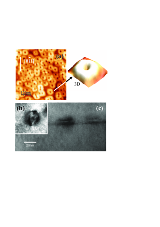
Atomic Force Microscopy (AFM) was used to investigate the surface morphology of the grown nanostructures as depicted in 1 (a), where an uncapped sample of QRs is shown with a typical density of about cm-2. The extracted profile of a single QR is shown in the inset. To study the optical properties of these nanostructures, the sample was capped with a 50nm layer . For the capped sample, morphological and structural analysis were carried out using a FEI Titan 80-300 Transmission Electron Microscope (TEM) equipped with an image Cs-corrector. TEM samples were prepared using standard mechanical polishing followed by dimpling and low-energy ion-milling using Fischione equipment. Figures 1 (a) and (b) show a plan-view and cross-sectional TEM images that show clear ring-like shapes. Figure 1 (b) displays a plan-view bright-field TEM image of a ring, taken close to zone axis with reflecting planes. The density and the diameter of the ring population can be directly determined from such images. Additional high-resolution imaging, 1 (c), was performed on cross-section samples that provided the ring thickness and also confirmed that they perfectly lie on planes. Magneto-PL experiments were performed at 2 K, with magnetic field up to 15 T, using a laser line of 532 nm. The luminescence was detected by a liquid nitrogen-cooled diode array.
To formulate a consistent picture of correlation between AB interference and interaction, we have used a simplified model according to which the two particle Hamiltonian of the pair interacting by means of a contact potential in a ring of radius and zero width threaded by a magnetic flux is described by VIVALDO
| (1) |
We used the same gauge as in Ref. AB1, , where is the angular position of electron (hole) and . The attractive interaction between the electron and the hole has been introduced by a short range term . The parameter is chosen so that the exciton ground state obtained in this model fits the reported value of the exciton binding energy. We have used the exciton binding energies equal to meV.LANDOLT
This Hamiltonian becomes separable if we change to center of mass and relative position coordinates, , , respectively, where , and . The exciton eigenfunction will be
| (2) |
where . Following Ref. AC, , the function satisfies Bloch’s theorem and the twisted boundary condition
| (3) |
where can be restricted to the reduced Brillouin zone, . Note that represents the probability density of finding the electron and hole angular positions differing by . The periodicity of in and determines that the center-of-mass angular momentum, in units of , assumes integer values and that (where ).AC Thus, given an integer value for , the parameter can be determined uniquely in the interval . Once we have determined , we can solve the eigenvalue problem for under the boundary condition (3). The corresponding eigenfunctions can be determined exactly and the exciton energy obtained from a set of transcendental equations, as reported in Ref. VIVALDO, .
At this point, it is easy to understand that several physical properties of this system will be invariant when the magnetic flux through the ring changes by a multiple of the quantum flux such as the total exciton energy. Moreover, we can examine the behavior of the oscillator strength that can be unambiguously related to the relative motion of the electron and the hole given by the function in Eq. (2). At T=0 K, the oscillator strength of the ground-state, , is given by
| (4) |
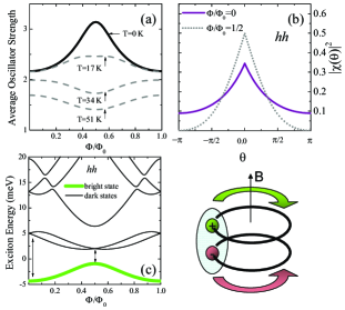
therefore is a periodic function on the magnetic flux, as represented in 2 (a). In the calculations, the band parameters used were: the in-plane masses and , where , and .LANDOLT Note that we used the heavy-hole ()-mass in the plane, assuming that the light-hole () exciton, with mass ,occupies a higher energy position due to strain effects. Some effects related to the -excitons will be discussed when necessary. In order to understand the oscillations, as shown in 2 (a), in terms of AB-like interference, we have displayed the function for zero flux and , in 2 (b). In both cases, is -periodic but for , the exciton wavefunction satisfies anti-periodic boundary condition (Eq. (3)) yielding the cancelation of the probability density at , which emulates an enhancement of the wavefunction confinement and subsequently its concentration near . Without interaction the correlation between the electron and hole disappears and the oscillations of the oscillator strength vanish. Thus, the Coulomb binding, although relatively weak due to its short range character, leads to a rather peculiar AB-interference detected optically as oscillations of the PL emission intensity, as suggested in Ref. RA, .
We may analyze two elements that invert the sequence of minima and maxima of the oscillator strength: the effect of (i) temperature and (ii) built-in electric fields in the QR plane. In order to take into account the temperature, we generalize Eq. (4) to include all excitonic states,
| (5) |
where is the oscillator strength for the th state with wavefunction , . As the temperature rises, the occupation of excited levels of the exciton becomes more probable.LIN In 2 (c) the exciton energy levels are displayed for -excitons where the first excited levels correspond to dark excitons. By increasing the flux, starting from up to , the dark exciton levels approach the bright-one. At finite temperature, the net occupation of the ground-state decreases as these levels come closer and reduces the thermalized oscillator strength and its amplitude. At relatively high temperatures, this effect transforms the maximum of the oscillator strength at into a minimum for the -exciton, as displayed in 2(a).
Another effect that can lead to the inversion of the maximum of the oscillator strength for the exciton ground-state is the existence of an in-plane electric field. This internal field can be caused by uniaxial strains and the subsequent piezoelectricity that can be relatively strong in self assembled 0D structures.PIEZO1 ; JA The in-plane electric field along -axis can be introduced into the Hamiltonian as
| (6) |
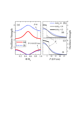
In order to solve this problem, we adopted a basis set of eigenfunctions of to expand the new solutions. It is easy to show that the electric field can only couple states with center of mass angular momenta differing by one. In general terms, we can expect that the oscillator strength will decrease with increasing electric field, since the electron and the hole are pushed appart. In 3 (a), the oscillator strength has been displayed as a function of the magnetic flux for both - and -excitons at two values of the in-plane electric field for T=0 K. It is obvious the inversion of the maximum. In turn, 3 (b) and (c) illustrate the oscillator strength for the exciton in the ground-state as a function of the electric field. A critical value of the field, , appears for both - and -excitons where the oscillation pattern becomes inverted. The stronger the electric field, the higher is the projection of the ground-state over states with odd angular function, . This is particularly critical at beyond , when becomes a pure odd function and . In our QR model, this condition leads to null oscillator strength at . Certainly, for a QR with finite size, this extreme reduction is not expected.
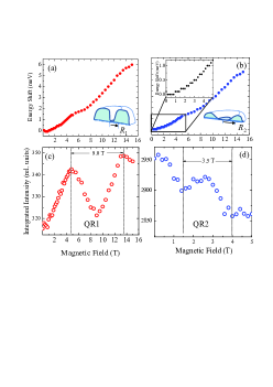
PL peak position energy vs. magnetic field: (a) emission band QR1 (b) QR2. (c) and (d) show the integrated PL intensity of QR1 and QR2, vs. magnetic field respectively. The insets in upper figures illustrate digram of the rings.
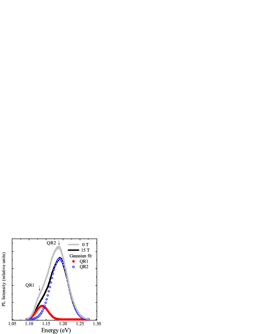
We performed experiments in self-assembled QRs structures searching for confirmations of the AB-interference just described. The QRs investigated here present a broad optical emission band ( meV) measured at 2 K, as shown in 4, and a weak shoulder ( meV) in the low energy range, labeled QR1 and QR2, respectively. We used Gaussian functions to fit two emission bands (circles in 4) attributed to the bi-modal QR distributions dominated, in this case, by high energy QRs. Under an external magnetic field applied along the growth direction a blue shift is observed for both emission bands. PL peak position and its integrated intensity are plotted in 5. The apparent energy oscillation (less than 0.5 meV) on the diamagnetic shift observed in both bands is attributed to the systematic fluctuation obtained in the fitting process, therefore, it was not considered in this work. However, the oscillation of the PL intensity (5 (c) and (d)) is a real behavior. We observed opposite direction of the oscillations for two emission bands as the field is increased, minima and maxima occurs in opposite sequence within different field range and period. The PL intensity oscillation of the band QR1 is in good agreement with the modulation of the oscillator strength shown in 2 considering an average QR radius of 11.6 nm. Therefore, it is attributed to the effect of the exciton interference in a ring-like system resulting in an oscillation on the oscillator strength in the presence of an external magnetic field. The opposite behavior observed for QR2, on the other hand, is rather compatible with the model including an electric field shown in 3, the presence of the electric field inverts the direction of the oscillator strength and results in an average ring radius of 19 nm. The fact that the emission band QR2 has higher transition energy and larger average radius than QR1 suggests that QR2 may present smaller ring width and height than those for QR1.
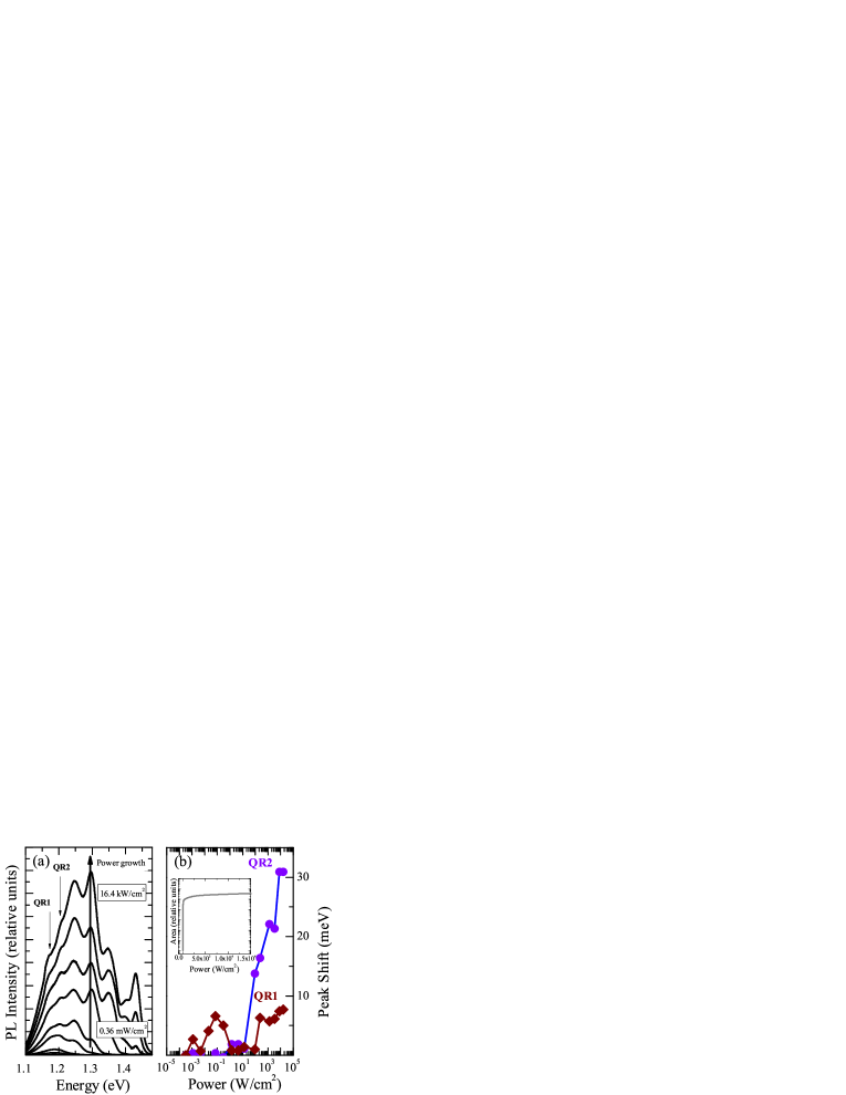
The effects of built in electric fields in the rings mentioned above has already been described in previous works JA when the ring is slightly elongated. During the QR growth anisotropic strain fields are formed in the (001) plane leading to an elongation of the ring in the direction.EUCLYDES This effect, which has been observed in QRs, yields a built-in electric field due to the piezoelectric effect. Additional optical experiments show the evidence of the presence of built-in electric fields in QR2 and negligible field values in QR1, which is consistent with the models discussed above. Figure 6 shows the PL spectra vs. excitation intensity. Increasing the excitation intensity we observed additional emission bands in high energy side region, which are attributed to the state filling of the excited states of the QR2 (dominant band). The main point of this experiment is that, as the carrier population increases in the QRs, the built-in electric field should be screened. In 6 (b) we plotted the energy shift of the QR1 and QR2 versus excitation intensity. We observed a blue shift of the emission band QR2 at the high excitation regime, suggesting the screening of the built-in electric field. The blue shift is not observed in the emission band QR1 where its peak energy remains practically constant confirming thus that the built-in electric field in those QRs is negligible. This result also corroborates the theoretical model used to explain the intensity oscillation of the magneto-optical emissions of QRs. However, the unclear point is why the built-in electric field related to the band QR1 is negligible, since the effect of the elongation should be applied for all rings. A possible reason is that the ring width corresponding to QR1 is larger than that for QR2, as mentioned above and the strain field relief for the former may be stronger than for the latter, thus resulting in a much lower piezoelectric field. Therefore we can attribute the sequence of minima and maxima observed in the intensity oscillations of QR2 to the effect associated to AB-interference combined with the in-plane electric field.
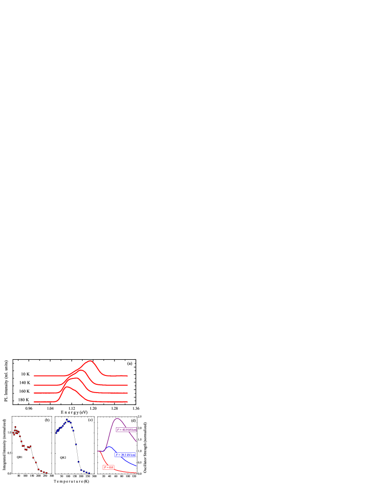
We also performed the PL experiments vs. temperature in order to investigate the temperature dependence of the excitonic emissions in QR, as discussed in 2. Figure 7 (a) shows the PL spectra obtained for several temperatures. At low temperature regime the PL spectra are dominated by the emission band QR2, whereas at temperatures above 160 K, it inverts and becomes dominated by QR1. This inversion, at high temperatures, is attributed to the transference of carriers between QRs, via wetting layer, favoring the lower energy states, similar to effects observed in QD systems.
We plotted in Figure 7 (b) and (c) the integrated intensity for each emission band vs. temperature. The decrease of the PL intensity is expected, as shown in Figure 2, due to the occupation of dark excitonic states. However, we observed an increase of the intensity for QR2 at K. This is another signature of the presence of an in-plane electric field in these QRs as corroborated theoretically by the results shown in 7 (d). The oscillator strength increase occurs by the activation of more efficient channels for optical recombination at excited states, where the angular separation provoked by the electric field is reduced.
The thermal activation energies obtained from Ahrrenius plots could give additional information on the carrier transference. We obtained two activation energies from emission band QR1. One of them at low energy of 13 meV, close to the energy separation between dark and bright (ground) exciton states shown in Figure 2, and the second one, of 160 meV, related to the PL quenching for T ¿ 150 K, observed in both bands and the total one. The latter is approximately the value estimated for the energy separation between QRs and wetting layer. These experimental results confirm that the inversion in the sequence of minima and maxima for the band QR2, in 5 (d), cannot be attributed to effects induced by temperature, since only for K an effective reduction of the ground-state occupation takes place (far above the temperature value where the oscillations in 5 (d) were detected, T=2 K).
In summary, we have observed and characterized by optical methods an AB-effect in nanoscopic QRs modulated by built-in piezoelectric fields. The AB-oscillations, traced by patterns of the PL intensity under increasing magnetic field, are consistent with the presence of two sets of rings with different radii in our sample. More interestingly, they show that the oscillation pattern in the PL integrated intensity for the largest radius rings has maxima and minima alternated relative to the signal from the smallest radius rings. Such inversion in sequence of the maxima and minima can be predicted by a simple theoretical model which takes into account the correlation between the electron and the hole either as a temperature effect or as an in-plane electric field effect. We have shown that the source of built-in piezoelectric fields is plausible and experimentally confirmed and, thus, we have discarded the temperature as another possible cause of the inversion since the experiments are done far below the value at which the presence of dark exciton states becomes relevant. In this way, we confirm that piezoelectric fields may have an important role in strained QR systems inducing a modulation to the AB-oscillations. Also, Coulomb correlation is a crucial factor for the observations reported in this work; without it, the correlation between electrons and holes vanishes and these oscillations disappear.
The authors are grateful to the Brazilian Agencies FAPESP and CNPq for financial support and the National Science Foundation of the U.S. through Grant # DMR-0520550.
References
- (1) J. M. García, G. Medeiros-Ribeiro, K. Schmidt, T. Ngo, J. L. Feng, A. Lorke, J. Kotthaus and P. M. Petroff, Appl. Phys. Lett., 71, 2014 (1997).
- (2) A. Lorke, R. J. Luyken, A. O. Govorov, J. P. Kotthaus, J. M. García and P. M. Petroff, Phys. Rev. Lett., 84, 2223 (2008).
- (3) F. M. Alves, C. Trallero-Giner, V. Lopez-Richard and G. E. Marques Phys. Rev. B, 77, 035434 (2008).
- (4) M. Grochol, F. Grosse and R. Zimmermann, Phys. Rev. B, 74, 115416 (2006).
- (5) P. A. Orellana and M. Pacheco, Phys. Rev. B, 71, 235330 (2005).
- (6) I. R. Sellers, V. R. Whiteside, I. L. Kuskovsky, A. O. Govorov, and B. D. McCombe, Phys. Rev. Lett. 100, 136405 (2008).
- (7) Y. Aharonov, D. Bohm, Phys. Rev. 115, 485 (1959).
- (8) Y. Aharonov, D. Bohm, Phys. Rev. 123, 1511 (1961).
- (9) A. Chaplik and Pis’ma Zh. Éksp, Teor. Fiz., 62, 885 (1995)[JETP Lett. 62, 900(1995)]
- (10) R. A. Römer, M. E. Raikh, Phys. Rev. B 62, 7045 (2000), Phys. Stat. Sol. (b), 221, 535 (2000).
- (11) T. Chakraborty and P. Pietiläinen, Phys. Rev. B, 50, 8460 (1994).
- (12) Andrea M. Fischer, V. L. Campo Jr., M. E. Portnoi, and R. A. Röomer, Phys. Rev. Lett. 102, 096405 (2009).
- (13) M. Hanke, Yu. I. Mazur, E. Marega, Jr., Z. Y. AbuWaar, G. J. Salamo, P. Schäfer, and M. Schmidbauer Appl. Phys. Lett. 91, 043103 (2007).
- (14) Landölt-Börnstein Comprehensive Index, edited by O. Madelung and W. Martienssen (Springer, Berlin, 1996).
- (15) C. H. Lin, H. S. Lin, C. C. Huang, S. K. Su, S. D. Lin, K. W. Sun, C. P. Lee, Y. K. Liu, M. D. Yang, and J. L. Shen, Appl. Phys. Lett. 94, 183101 (2009).
- (16) A. Schliwa, M. Winkelnkemper, and D. Bimberg, Phys. Rev. B, 76, 205324 (2007).
- (17) J. A. Barker, R. J. Warburton and E. P. O’Reilly, Phys. Rev. B, 69, 035327 (2004).