Temperature dependent Néel wall dynamics in GaMnAs/GaAs
Abstract
Extensive Kerr microscopy studies reveal a strongly temperature dependent domain wall dynamics in Hall-bars made from compressively strained GaMnAs. Depending on the temperature magnetic charging of domain walls is observed and nucleation rates depend on the Hall-geometry with respect to the crystal axes. Above a critical temperature where a biaxial-to-uniaxial anisotropy transition occurs a drastic increase of nucleation events is observed. Below this temperature, the nucleation of domains tends to be rather insensitive to temperature. This first spatially resolved study of domain wall dynamics in patterned GaMnAs at variable temperatures has important implications for potential single domain magneto-logic devices made from ferromagnetic semiconductors.
pacs:
75.50.Pp, 75.60.Ch, 75.60.JkThe ferromagnetic semiconductor GaMnAsohno has been
extensively studied in the past few years not only in the viewpoint
of basic science but also focusing the attention on properties that
can lead to novel applications in spin-based electronics and
magneto-logic devices jungwirth ; dietl . For the latter, a good
understanding of domain wall (DW) dynamics is needed in order to
control processes such as the DW nucleation and propagation. In
ferromagnetic GaMnAs with in-plane magnetization, magnetic reversal
processes have been studied mostly by means of
magneto-transport tang ; pappert , however with very limited
gain of local information on DW nucleation and motion. Very recently
single DWs have been resolved in the static limit by means of
electron holography on the scale of a few
micrometers sugawara08 with high spatial resolution. In
contrast, we have shown that Kerr microscopy provides full time and
spatially resolved information on the dynamics of in-plane magnetic
domains during the magnetization reversal on the scale of a few
hundred micrometers ourpaper .
Due to the low Curie-temperatures well below room
temperature of most ferromagnetic semiconductors like GaMnAs it is
of technical interest to study these materials in the highest
possible temperature range just below . In this work we present
a careful characterization of the temperature dependent biaxial and
uniaxial magnetic anisotropies in compressively strained GaMnAs and
their influence on the evolution of the magnetic domain structure
thereby identifying limits for domain wall logic devices in the high
temperature regime. A preferential DW alignment is found to be
linked to the change in the position of the easy axis given by the
temperature dependence of the uniaxial and biaxial anisotropy
contributions. An increase in the number of domain nucleation
centers is observed beyond a critical temperature where a
biaxial-to-uniaxial anisotropy transition takes place. The
dependence of this behaviour on the geometry of the device
is also presented.
The material under study, consists of GaMnAs epilayers of 170 nm
thickness grown on GaAs(001) by molecular beam epitaxy (MBE). The
nominal Mn concentration is (2.3 0.1)% and has been
estimated on the bases of flux ratios. A more detailed description
of the sample growth and material characterization has been given
elsewhere ourpaper . The GaMnAs devices used in the Kerr
microscopy experiments are Hall bars of 200m width fabricated
by standard photolithography and ion milling.
Magnetic characterization of unpatterened, virgin GaMnAs epilayers
For a full characterization of the magnetic anisotropy within the GaMnAs epilayer we performed temperature dependent SQUID as well as magneto-optical Kerr effect (MOKE) measurements with magnetic fields applied in various in-plane directions. SQUID measurements were performed cooling the sample in a field of 1000 Oe and applying a field of Oe during the measurement. The results are shown with in Fig. 1(a) for fields along three directions [10], [110] and [100]. Also plotted is the magnetization versus temperature (Fig. 1(a), inset) in a saturating field of T. From the temperature dependent magnetic response at non-saturating fields of Oe for different directions the temperature dependence of the anisotropy constants can be estimated assuming a Stoner-Wohlfahrt coherent rotation of the magnetization following the total energy density , where and are the biaxial and uniaxial anisotropy constants, M is the magnetization, H the magnetic field, and and are the angles of M and H with the [10] direction. For each temperature the measured SQUID signal is determined simply by the equation system
| (1) | |||
| (2) |
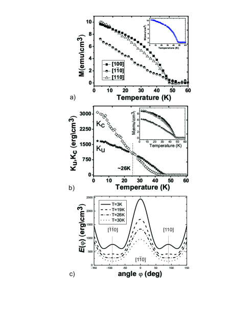
Here is the measured projection of the magnetization on the axis of the SQUID pick-up coils, which are aligned parallel to the magnetic field. While is known from the SQUID measurement at saturating fields, and are temperature dependent parameters to be derived by fitting. Assuming a magnetization dependence of the anisotropy constants close to and wang we can use equations (1) and (2) to fit the SQUID data as shown in the inset of Fig. 1(b). The fits shown for the three directions [10], [110] and [100] are derived using one and the same fit parameters and in addition to the magnetization exponents 1.8 and 4.1 for the expressions of and , respectively.
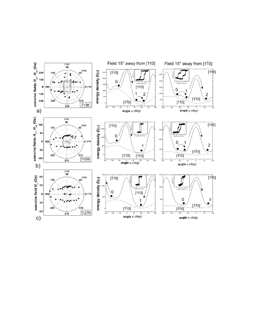
In Fig. 1(b) the temperature dependence of and is plotted as a result of the fitting procedure. A clear crossover is observed from biaxial to uniaxial magnetic anisotropy at approximately 26K where . As a consequence along the [110] direction the second derivative of the energy, , changes sign at and the number of local minima in is reduced from 4 to 2 due to the disappearance of the biaxial induced energy barrier in the [110] direction (see Fig. 1(c)). As extensively shown in magneto-transport measurements by Pappert et al. pappert this crossover is directly visible in polar coercivity plots of Fig. 2, which summarize the coercive fields derived from MOKE hysteresis loops taken in different directions with respect to the [10] crystal axis. The shape of the angular dependence of the coercivities at K and K clearly confirms the change from a four-fold dominated to a two-fold dominated symmetry at low and high temperatures, respectively. At low temperatures in agreement with the literature the biaxial four-fold symmetry leads to two step reversals via intermediate local minima in . Specifically for our samples transitions at K have been shown to be mediated by two individual domain walls with DW angles 120∘ and 60∘, respectively ourpaper , triggered at the coercive fields and . The reversal via an intermediate state is illustrated in the two right plots of Fig. 2(a) where is shown for fields applied along angles away from the [110] and [10] directions, respectively. For the measured values at K in the respective direction were taken. From the diagram it also becomes immediately clear that we expect measured close to the [110] directions to be higher compared to [10] because in the former case the barrier that has to be overcome is governed by the larger uniaxial part of the anisotropy landscape. Since we will later characterize DW transitions in detail using Kerr microscopy we want to stress the fact that measuring the coercivities at different can trigger magnetization transitions with either clockwise (CW) or counter-clockwise (CCW) sense of rotation. From Fe/GaAs thin film systems with an equivalent magnetic anisotropy symmetry it is known that the sense of rotation changes whenever the magnetic field direction crosses a local minimum or a maximum in the magnetic energy landscape Daboo95 .
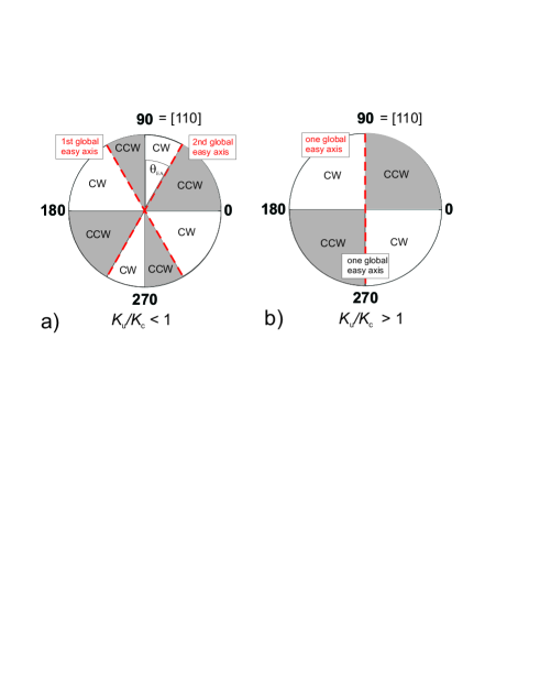
Therefore, as shown in Fig. 3(a), at low temperatures where , the sense of the transition changes 8 times when is swept over the full angle range 111The change of the sense at the maxima of at [10] and [110] is directly visible when measuring the magneto-transport in our Hall-bars. The transverse Hall-voltage changes sign for measurements away from the respective directions.. Four of the eight sign changes occur when the magnetic field direction crosses the two equivalent global easy axis directions located at angles away from the [110] direction as shown in Fig. 3(a). At high temperatures K in agreement with Fig. 2(c) only one single transition at is observed and we expect DWs with angles 180∘. Accordingly, we expect that the sense of the transitions only change sign 4 times during a full angle sweep of (see Fig. 3(b) for the case ). At K in a very narrow angle window close to the [10] low coercivities of about Oe are found. When the field direction sufficiently deviates from the [10] axis, coercivities quickly jump to higher values larger than Oe. In an angle window away from the [110] direction the values of the coercivities are stable around 30 Oe indicating that in this region the magnetic reversal is highly reproducible and not critically dependent on the sample orientation. Therefore, applying the field along the [110] direction at different temperatures below and beyond the crossing point of and should allow for the observation of the transition between 120∘ and 180∘ DWs. From an application point of view this direction is interesting since in this regime the transition was shown to be propagation dominated with a relatively small number of domains involved in the process ourpaper .
Observation of temperature dependent domain wall dynamics in patterned GaMnAs Hall-bars
The Kerr-microscopic observation of magnetic domains was performed
using the same procedure as described in Ref. ourpaper .
Before presenting the microscopy results which focus on the
temperature dependent dynamics of DWs for magnetic fields applied
close to the [110] direction we would like to shortly discuss the
expected change of the DW angle and sense of
rotation with temperature as well as with increasing deviations
from the [110] direction.
From simple
symmetry arguments reflected in Fig. 3 it is evident
that generally small deviations of to both
sides of the [110] direction will trigger DW transitions of opposite
sense. However, despite the opposite sense in rotation the absolute
DW angles remain exactly the same. More specifically, at low
temperatures K and CW
(CCW) deviations lead to CW (CCW) transitions at and
, whereas for CW
(CCW) deviations lead to a CCW (CW) transition. The angle
is shown in Fig. 3(a). For
K CW (CCW) deviations always lead to a CCW (CW) transition.
For a full understanding of DW dynamics at different temperatures it
is therefore important to trace the temperature dependent global
easy axis direction. To give an example of the influence of
on , Fig. 4 shows the
temperature dependent angle of the global
easy axis direction with respect to [110] at zero magnetic field
together with the expected DW angle of the first transition at
for and for a field deviation
with respect to [110]. The easy axis
directions were obtained by tracing one of the two energy minima in
closest to the [110] uniaxial easy axis (see
Fig. 1(c)). is determined by
and given in Fig. 1. As expected at
26 Kelvin, the temperature of the crossing between and
(see Fig. 1), the global easy axis starts to be
fully aligned with the [110] direction. The calculation of the DW
angle of the first transition includes the temperature dependence of
the coercive field applied close to the [110] direction. Coherent
rotation effects in two domains separated by the DW are thus taken
into account.
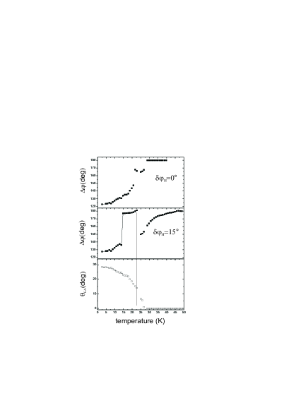
The DW angle for
and for the field deviation shows two
distinct jumps caused by the sequential destabilization of the
initial and the final magnetization state of the transition. In the
three middle row plots of Fig. 2 this effect is
illustrated for the case . At around
20K the intermediate state of the CCW two-step transition becomes
instable and the magnetization rotates to the final state in one
single step (in the MOKE hysteresis shown in the inset the
intermediate step has vanished). thus increases
abruptly at this point, however the CCW sense of the transitions is
preserved. Finally, at temperatures K where
(see
Fig. 4) the sense of the transition changes to CW and the
initial magnetization state rotates towards the [0]
direction leading to a reduction in . As the
temperature is further elevated
the initial and final magnetization states approach the global easy axis direction along [110].
In the following the effect of the temperature dependent change from
four-fold to two-fold symmetry in on the DW dynamics is
studied on the basis of extensive Kerr microscopy measurements with
magnetic fields applied close to the [110] direction.
Domain wall alignment - Charging of walls
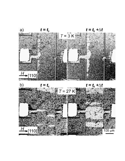
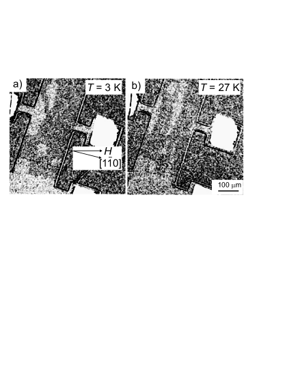
The Kerr images in Fig. 5(a) and (b) (Hall-bar [110]) and Fig. 6(a) and (b) (Hall-bar [10]) show typical domain structures for the field applied along the [110] direction at 3K and 27K, respectively. For all four cases two consecutive frames at times and were extracted from a movie to picture the time evolution. Fig. 5 and Fig. 6 demonstrate that the alignment of the DWs with respect to the [110] direction is clearly temperature dependent. While at low temperatures the DWs avoid the alignment with the [110] direction along the Hall bar they prefer the parallel alignment at higher temperatures in both cases. Only the DW nucleation behavior seems to be dependent on the Hall-bar orientation. Here we observe that only in Fig. 6 nucleation happens preferentially at the long sides of the Hall-bar. We will discuss nucleation effects in detail in the next section.
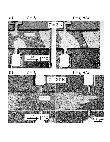
In most magnetic systems the alignment of DWs is correlated to the surface divergence of the magnetization at the domain boundary due to magnetization components normal to the DW bookdomains ; bookred ; bookblue . In general, this creates so-called magnetic charges proportional to at the DW boundary accompanied by a cost of stray field energy, where and are the magnetization vectors of the two domains separated by the DW and the wall normal facing towards domain 2. Hence, in our GaMnAs samples, in order to avoid magnetic charges, DWs should be aligned along [110] for the low temperature 120∘ DW transition with fields along [110]. At higher temperatures in the case of DW transitions where the magnetization vectors and are collinear with the global easy axis along [110] we expect the system to try and avoid head-to-head type of boundaries with maximum amounts of magnetic charges vogel . In agreement with the latter, the observed DWs at 27 K show typical zigzag patterns throughout the reversal dynamics with pointing preferentially parallel to the [10] direction where holds. At low temperatures, however, out results are clearly not according to the above described model. As discussed, the reversal dynamics shown in Fig. 5 (a) with the field applied along the [110] direction corresponds to a 120∘ DW ourpaper where the initial and final magnetization states and are aligned with two of the biaxial global easy axes which lay at from the [110] direction (see Fig. 4). The preferential orientation of the DWs around 25∘ away from [10] observed in the Kerr images, thus, points to significant amounts of magnetic charges accumulated at the walls.
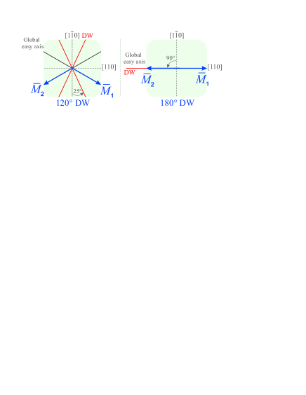
Fig. 7(left) and (right) summarizes the experimentally
observed DW orientations for the case of 120∘ and
180∘ DW transitions at low and high temperatures together
with the respective easy axis directions. It should be noted at this
point that the DW orientations are found to be the same in our
virgin film samples and therefore are not a consequence of the
Hall-bar patterning process.
Before we start to discuss the physics leading to the
observed DW alignment behavior it is helpful to estimate the
expected contributions of the stray field to the energy density. In
the diluted ferromagnetic semiconductor GaMnAs the magnetization is
about 2 orders of magnitude lower compared to typical 3 metal
ferromagnets like Fe and therefore stray field energy contributions
to the total energy density are generally reduced by a factor
10-4. One of the consequences is that in GaMnAs films Néel
walls are energetically preferred to Bloch walls up to relatively
large film thicknesses . In this regime the system
avoids magnetic surface charges at the film surfaces and encounters
volume charges within the Néel wall. It was shown that the
critical thickness can be approximated by , where is the exchange coupling constant.
With a typical value of for
GaMnAs and magnetization values of the order of
10 one gets a critical thickness of about
m (compare to Permalloy where =50nm). Thus,
we can assume that the magnetic dynamics in our GaMnAs films of
170nm thickness is governed by Néel-type walls in agreement with
experiments by Sugawara et al.. sugawara08 .
The low magnetization value also reduces the stray field energy
density caused by magnetic charges situated at a DW. It
is given by for an infinitely extended DW. For epitaxial Fe films of
thickness grown on GaAs with a predominant cubic
anisotropy and large values of the order of
1 a strict preferential DW
alignment according to the stray field minimization condition
has been reported by Gu et al. gu . The
authors observe the alignment of 90∘ and 180∘ DWs
with the hard and easy axis, respectively, when the field is applied
along the easy axis parallel to the cubic crystal symmetry
direction. For our GaMnAs samples with low concentrations of Mn,
however, stray field energy densities are only of the
order of 100 at most. Moreover, in thin
films is further reduced due to the limited lateral
extension of the DW when oriented perpendicular to the film. It can
be shown that stray fields produced by magnetic charges in laterally
confined Néel walls decay like at large distances away
from the wall Kronmueller65 . As a consequence for very thin
films more complex Néel wall shapes occur and total wall
energies have to be evaluated numerically including exchange
stiffness and magnetic anisotropy, which leads to solutions
including isolated charged walls with hubert79 . From calculations by A. Hubert hubert79
with therein defined dimensionless parameters and
one expects charged 120∘ DWs in
our GaMnAs samples of thickness nm with and
in accordance with our results of the
Kerr-measurements at . DW charging effects similar to ours are
visible also in epitaxial Fe films in the ultrathin film limit grown
on GaAs. Although the authors of Ref. gu did not discuss this
aspect in detail the film thickness dependent cross-over from
uncharged to partly charged 90∘ DWs clearly shows in their
Lorentz microscopy data for and , respectively Daboo95 . In GaMnAs epilayers Sugawara
et al. found both 90∘ Néel walls oriented along
the [10] direction and 20∘ away from the
[10] (see DW (iii) in Fig. 1(b) of Ref. sugawara08 ).
The latter configuration again should correspond to a charged wall
although the authors did not comment on this issue. It should be
noted, however, that since the Lorentz microscopy technique only
permits the observation of domains close to the film edges where a
non-magnetic reference signal is available, the local orientation of
the DWs can also be affected by inhomogeneous morphology induced by
the lithography process as well as flux closure processes.
Temperature dependence of domain nucleation
As mentioned in the previous section a clear asymmetry in the
nucleation behavior is observed for Hall-bars oriented in the [110]
and [10] direction (see Fig. 5 and
Fig. 6). While in the former case, for both
120∘(K) and 180∘(K) DWs, a small number
of domains occur and the contact pads of the Hall bar devices tend
to serve as nucleation centers, for [10] oriented Hall-bars
nucleation events happen preferentially at the long sides of the bar
and appear larger in number.
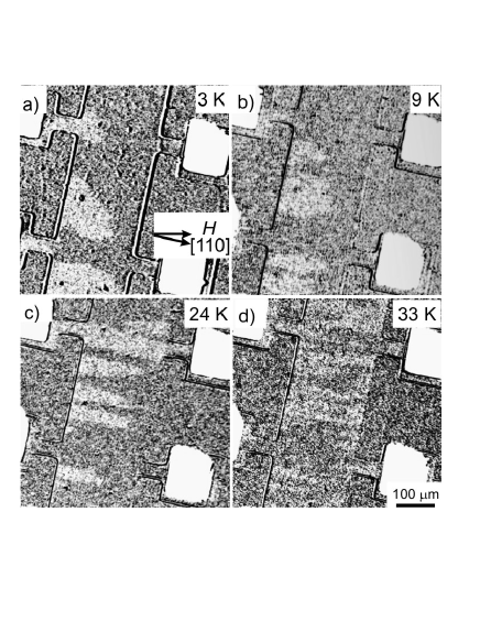
In order to study influences of geometry and temperature on the
nucleation in more detail, Kerr microscopy was performed in small
temperature steps on a Hall-bar having its longitudinal axis along
the [10] axis. We observe that below temperatures of Kelvin the number of domains involved in the transition remain
fairly small and constant as shown in Fig. 8 (a) and (b)
corresponding to temperatures of 3 and 16 Kelvin, respectively.
However, beyond this temperature the number of nucleation events at
the long sides of the Hall-bar edge grow dramatically and at the
same time domains become increasingly elongated as illustrated in
the Kerr images in Fig. 8(c) and (d) taken at 24 and 33
Kelvin, respectively. The number of domains involved in the reversal
process versus temperature are plotted Fig. 10 (open
symbols) in a temperature range going from 3 to 33 Kelvin and show
an exponential behavior. Due to the decreasing contrast in the Kerr
signal with decreasing magnetization values Kerr images could not be
evaluated
in the temperature range between 33 Kelvin and .

Comparing the nucleation dynamics for the Hall-bar oriented in the
[110] and [10] directions it is evident that only
180∘ DWs appearing at temperatures around 25 Kelvin
are strongly affected by the orientation of the Hall bar with
respect to the crystal axis and field vector. Generally, the Kerr
images in Fig. 8 confirm that for fields applied close
to the [110] direction nucleation of domains is happening at film
edges facing the [110] direction. Indeed, Fig. 5 (a)
and (b) show that domains are never nucleated at the edges facing
exactly the [10] direction. Instead nucleation in
Fig. 5 happens at the square shaped Hall-bar pads with
two edges facing [110] or at the far Hall-bar ends (not visible in
the Kerr images) again facing [110]. To prove that the asymmetry is
indeed connected with the crystal orientation we looked at a
Hall-bar patterned in the [110] direction with an applied field
close to the [10] direction (see Fig. 9). In
accordance to our earlier work ourpaper we see multiple
nucleation events within the film at low temperatures characteristic
for DW transitions and no preferential nucleation
at the sides of the Hall-bar. At high temperatures K again the
domains are elongated along the easy axis direction [110], however
this time preferential nucleation at the long sides of the Hall-bar
is not observed.
Anisotropic nucleation of domains in thin ferromagnetic films as
observed in Fig. 8, where the observed preferred
nucleation occurs at the Hall-bar sides [10], can have
different origins:
Lithography induced Anisotropies: During the Hall-bar
lithography process differences in the edge profiles along [110] and
[10] can be introduced. As an example it is known that the
wet etching process of GaAs exhibits a different dynamics in the
respective directions, leading to different edge profiles. However,
the ion milling technique used in our case leads to direction
independent processing and a homogeneous edge profile in all
directions of the Hall-bar. This was verified using x-sectional
scanning electron microscopy. Also lattice relaxation effects as
observed at stripe edges Wunderlich ; Wenisch that lead to
local changes in the magnetic anisotropy energy should
be equal in strength for edges [110] and [10]. We
therefore claim the observed asymmetric nucleation behavior not to
be a consequence of the Hall-bar patterning process.
Anisotropies through closure domains: Anisotropies in the
nucleation rates can be induced by local dipolar fields, which decay
like away from the edges and trigger flux closure domains. In
micropatterned biaxial epitaxial Fe films on GaAs DW transitions of
90∘ type are triggered preferentially at film edges where
the rotation of the magnetization due to local dipolar fields has
the same sense as the DW transition itself Ebels97 . The local
rotation of can then be understood as a partial transition due
to dipolar fields which facilitates the domain nucleation induced by
the external field . Indeed for the CCW 120∘ DW
transitions shown in Fig. 8 (-field that induces the
transition is slightly rotated CW from the global easy axis
direction) we see nucleation at the edges [10] where
the dipolar fields will rotate the magnetization vector in the
common sense. The opposite is true for edges [110]. In the
measurement configurations shown in Fig. 5(a) and
Fig. 6(a) due to small deviations
of the field direction from [110] the sense
of the transition can be either CW or CCW. However, independent of
that again the local rotation of at the [110] edges is opposite
in sense and therefore do not support nucleation in accord with our
experimental results. At higher temperatures K and K
(Fig. 8(c) and (d)) transitions are CW (-field that
induces the transition is rotated CCW by from [110]).
Since the easy axis is exactly along [110] it is obvious that
nucleation is again only facilitated at edges [10],
where produces maximum stray fields. However, we believe in this
case the sense of local rotation is not a priori predictable.
While the model of closure domain formation supports our
experimental observations for fields applied close to [110], the
results in Fig. 9 do not fit into this picture. At low
temperatures for CCW 60∘ DWs we would expect nucleation at
the edges [110] and at high temperatures nucleation at those
[10]. Instead we observe rather statistical nucleation
within the entire device. We again tend to attribute this difference
in nucleation dynamics to the reduced DW nucleation/propagation
energy with respect to 120∘
DWs ourpaper . Moreover, in the case of Fig. 9 at
low temperatures stray fields proportional to the projection of on [10] are
significantly reduced when compared to those
in Fig. 8.
It remains to discuss the drastic increase of the number of domains involved in the transitions above temperatures K. The problem resembles that of Fatuzzo’s domain-nucleation model developed for ferroelectrics Fatuzzo . As described in the beginning of this section the increase of is accompanied by a change in the average width of the domains, where is the dimension of domains measured along [10] in Fig. 8. From the time resolved dynamics in our Kerr-movies above K it is evident that after nucleation of a domain at the Hall-bar edges, DW propagation is mainly happening in the [110] direction with little change in of the respective domain. As proposed by Fatuzzo we therefore attribute the drastic increase in to a complex interplay of temperature dependent nucleation rates at the film edges, a reduced DW mobility along [10] and effects of coalescence of domains. If is the average domain width at the coercive field where of the area of the film has switched, then the respective number of domains in a given section of the Hall-bar with a length [10] is approximately . Here will be a function of the mobilities along and and the nucleation rates . With this we can qualitatively understand the temperature dependent nucleation dynamics. The Kerr data prove that with increasing temperature and especially for K the ratio between and is significantly shifted towards propagation along [110], which assuming a constant would reduce and increase . On the other hand we expect to increase with temperature according to a thermally activated process which supports coalescence of domains at an early stage after nucleation. Generally, both a decrease in the mobilities and leads to an increase in the coercive field at constant sweep rates of the magnetic field. Indeed, the temperature dependence of shown in Fig. 10 (full symbols) indicates a distinct decrease in slope at K, which points towards a change in the mobilities and/or ( decreases rather monotonously in this temperature range as shown in the inset of Fig. 1(a)). Sudden changes in or would not be unexpected since they occur in close vicinity to the crossing point between and (26 Kelvin), where the magnetic transitions change their character. Above the crossing temperature we interpret the drastic increase in to be mainly due to a monotonous reduction of .
Conclusions
This work presents an extensive characterization of the temperature
dependent magnetic domain wall dynamics in Hall-bars made from
compressively strained GaMnAs and identifies limits for single
domain wall logic devices in the high temperature regime. Kerr
microscopy allows to locally observe nucleation events of domains as
well as the alignment and propagation behavior of domain walls. A
correlation of the preferential domain wall alignment with respect
to the temperature dependent magnetic easy axis direction is found.
The latter is determined by the temperature dependent in-plane
uniaxial and biaxial anisotropy energy contributions. At low
temperatures magnetically charged domain walls with domain wall
angles considerably smaller than are observed. Above
the biaxial-to-uniaxial transition temperature this charging effect
is lost and domain walls are oriented along the easy axis. Domain
nucleation is happening almost exclusively at Hall-bar edges aligned
along the [10] uniaxial hard axis direction. This behavior
is attributed to small demagnetizing fields contribution at the
edges of the device, that locally facilitate the magnetic transition
and therefore nucleation of domains. This effect is asymmetric and
favors nucleation at edges [10]. This first extensive
study of domain nucleation and propagation dynamics at variable
temperatures in GaMnAs shows that multi-domain states can be avoided
by a suitable device geometry. This together with our finding that
the orientation of domain walls can be tuned by the ratio between
uniaxial and biaxial anisotropy energy has important consequences
for applications in the field of magneto-logics and in particular
for single domain wall devices where domain walls are manipulated
through spin-polarized currents.
Acknowledgments
We would like to thank Prof. H. Kronmüller for valuable discussions and Ulrike Waizman for conducting the SEM measurements.
References
- (1) H. Ohno, Science 281, 951 (1998).
- (2) T. Jungwirth, J. Sinova, J. Masek, J. Kucera, A. H. MacDonald, Rev. Mod. Phys 78, 809 (2006).
- (3) T. Dietl, H. Ohno, F. Matsukura, J. Cibert, D. Ferrand, Science 287, 1019 (2000).
- (4) H. Tang, R. Kawakami, D. Awschalom, M. Roukes, Phys. Rev. Lett. 90, 107201 (2003).
- (5) K. Pappert, C. Gould, M. Sawicki, J. Wenisch, K. Brunner, G. Schmidt, L. W. Molenkamp, New J. Phys. 9, 354 (2007).
- (6) A. Sugawara, H. Kasai, A. Tonomura, P. D. Brown, R. P. Campion, K. W. Edmonds, B. L. Gallagher, J. Zemen, and T. Jungwirth, Phys. Rev. Lett. 100, 047202 (2008).
- (7) L. Herrera Diez, R. K. Kremer, J. Honolka, K. Kern, A. Enders, M. Rössle, E. Arac, E. Placidi, F. Arciprete, Phys. Rev. B 78, 155310 (2008).
- (8) K.Y. Wang, M. Sawicki, K. W. Edmonds, R. P. Campion, S. Maat, C. T. Foxon, B. L. Gallagher, and T. Dietl , Phys. Rev. Lett. 95, 217204 (2005).
- (9) A. Hubert, R. Schaefer, Magnetic Domains: The analysis of magnetic microstructures, Springer-Verlag, Berlin, (1998).
- (10) K. H. Stewart, Ferromagnetic Domains, Cambrdge University Press, Cambridge, (1954).
- (11) R. S. Tebble, Magnetic Domains, Methuen, London, (1969).
- (12) I. Horcas, R. Fernández, J. M. Gómez-Rodríguez, J. Colchero, Rev. Sci. Instrum. 78, 013705 (2007).
- (13) J. Vogel, S. Cherifi, S. Pizzini, F. Romanens, J. Camarero, F. Petroff, S. Heun, A. Locatelli, J. Phys.: Condens. Matter 19, 476204 (2007).
- (14) E. Gu, J. A. C. Bland, C. Daboo, M. Gester, L. M. Brown, R. Ploessl, N. J. Chapman, Phys. Rev. B 51, 013705 (1995).
- (15) H. Kronmüller, phys. stat. sol. 11, K125 (1965).
- (16) A. Hubert, IEEE Trans. Mag. 15, 1251 (1979)
- (17) C. Daboo, R.J. Hicken, E. Gu, M. Gester, C. Gray, D.E.P. Eley, E. Ahmad, J. A. C. Bland, R. Ploessl, N. J. Chapman, Phys. Rev. B 51, 015965 (1995).
- (18) S. Wunderlich, A. C. Irvine, J. Zemen, V. Holý, A. W. Rushforth, E. De Ranieri, U. Rana, K. Výborný, J. Sinova, C. T. Foxon, R. P. Campion, D. A. Williams, B. L. Gallagher, T. Jungwirth, Phys. Rev. B 76, 054424 (2007).
- (19) J. Wenisch, C. Gould, L. Ebel, J. Storz, K. Pappert, M. J. Schmidt, C. Kumpf, G. Schmidt, K. Brunner, L. W. Molenkamp, Phys. Rev. Lett. 99, 077201 (2007).
- (20) U. Ebels, A.O. Adeyeye, M. Gester, C. Daboo, R.P. Cowburn, and J.A.C. Bland, J. Appl. Phys. 81, 4724 (1997).
- (21) E. Fatuzzo, Phys. Rev. 127, 1999 (1962).
- (22) G. Vèrtesy, I. Tomáš, L. Pust, and J. Pačes, J. Appl. Phys. 71, 3462 (1992).