Spin-bias driven electron properties of a triple-quantum-dot ring
Abstract
Electron transport through a three-electrode triple-quantum-dot ring with the source electrode of spin-dependent splitting of chemical potentials (spin bias) is theoretically investigated. We find clear charge and spin currents in the drain electrodes driven by the spin bias, despite the absence of charge bias between the source and drain electrodes, and their directions and amplitudes can be adjusted by altering the structure parameters or magnetic field. The distinct characteristics of spin-bias driven persistent charge and spin currents in the ring are also shown. When an appropriate charge bias is applied, the single-spin electron motion can be achieved in this structure.
The manipulation and control of the behaviors of electron spins in nanostructures have become one subject of intense investigation due to its relevance to quantum computation and quantum information.Ohno ; Dasarma The electron spin in quantum dot (QD) is a natural candidate for the qubit, QD has therefore been regarded as an elementary cell of such a field and much attention has been paid to the manipulation of the electron spin degree of freedom in QD for its application.Loss ; Loss2 However, one of the challenge is to efficiently realize the spin transport without any appreciable charge transfer, for the reason that the spin is difficult to be manipulated by a charge bias voltage. Many schemes have been proposed to work out this problem, based on the case of a charge bias between two leads with a magnetic field or the spin-obit coupling for a QD system.Datta ; Rashba ; Rashba2 ; Sun Despite these existed works, any new suggestions to realize the pure spin current are still necessary. Recently, it has been reported that spin bias in leads for mesoscopic systems can be feasible,Nagaosa ; Hubner ; Cui ; Li ; Jpn which induces rich physical phenomena and potential applications different from the traditional charge bias.
In this letter, we propose a theoretical approach to realize the pure spin transport in a three-terminal triple-QD ring by assuming the source electrode of spin bias. Our theoretical investigation indicates that it is possible to form the pure spin current in either normal lead. Meanwhile, the spin-bias driven pure persistent spin current is apparent with its adjustable direction and amplitude. In the case of an appropriate charge bias applied, the single-spin electron transmission can also be achieved.
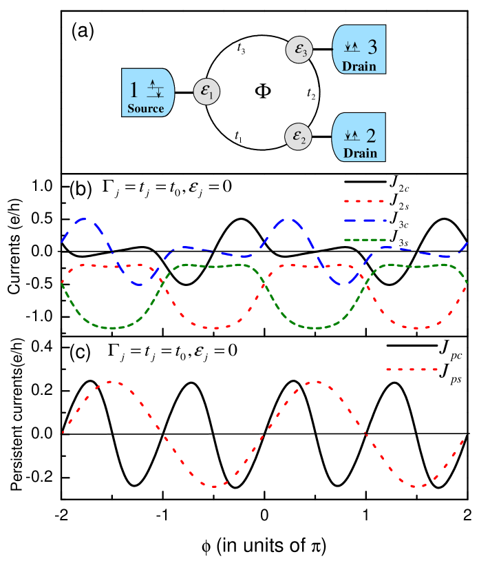
The structure under consideration is illustrated in Fig.1(a), and the Hamiltonian to describe the electron motion in the system can be written as . Here and ( and ) is an operator to create (annihilate) an electron of the continuous state in lead- (QD-) with being the spin index, and and is the corresponding single-particle energy with to . denotes the intradot Coulomb interaction, and represents the interdot hopping coefficient. In the case of the identical QDs distributed in the ring equidistantly, we can use uniform parameters to denote the interdot hopping coefficients, which is real at the zero-magnetic-field case. If a magnetic field is applied perpendicular to the ring plane, in the symmetrical gauge it becomes with , where is the magnetic flux threading the ring and is the magnetic flux quantum. By means of the Green function technique, at zero temperature, the current flow in lead- can be written as ,Meir ; Gong1 where is the transmission function, describing the electron tunneling ability from lead- to lead-, and is the Fermi distribution function of -spin electron in lead-. , the strength of the coupling between QD- and lead-, can be usually regarded as a constant. and , the retarded and advanced Green functions, obey the relationship . By adopting the equation of motion method, we can work out the retarded Green function by means of the second-order (i.e., Hubbard) approximation to truncate the higher-order Green function without the electron correlation being considered.Gong1 In order to clarify the electron and spin transport behaviors in such a structure, the charge and spin currents in lead- are defined respectively as and . In addition, the persistent current for the -spin electron in the QD ring can be given by Hancock with and , so the persistent charge and spin currents in such a ring are thereby well-defined with and .
Consider the chemical potentials of electrons in lead-1 ( the Source ) are spin-dependent, i.e., , whereas in the other leads ( the Drains ) with being the charge bias voltage between the leads and the spin bias, we now proceed on to investigate the electron transport properties in such a double-channel structure. Before calculation, we assume the uniform interdot hopping as the unit of energy and as the zero point of this system, and, the spin bias is taken to be .
With the adjustment of the threading magnetic flux, the current flows in the drains (i.e., lead-2 and lead-3) are first calculated in the zero-charge-bias case. The relevant parameters take the values as , whereas , the QD levels, are fixed at zero. The many-body terms are here not taken into account, since we are only interested in the electron and spin transport. Fig.1(b) shows the changes of the charge and spin currents in the drains versus the magnetic phase factor , respectively. It can be first found that, the amplitudes and directions of the charge currents in the two drains are tightly dependent on the tuning of magnetic flux with the periodicity , but obviously they vary out of phase; on the other hand, due to the consideration of spin bias, there also distinctly emerge spin currents in the two drains, and they reach their maxima alternately with the adjustment of magnetic flux. Furthermore, in the range of the magnetic flux factor from to [ to ], both the amplitudes of the charge and spin currents in lead-2 (lead-3) are suppressed, which indicates that the electron traveling between lead-1 and lead-2 (lead-3) is forbidden. In contrast to the above case, when the magnetic flux is tuned in the other regimes the electron transmission in the two channels are correspondingly allowed and at the position of [ ] the direction of the charge current is just inverted, where the pure spin current comes into being in lead-2 ( lead-3 ) with its maximal amplitude. Also, we can find that in the regimes where the electron transport is allowed, the amplitudes of the spin currents are larger than those of the charge currents, so high-efficiency spin injection can be realized in this structure.
Since the structure of quantum ring, the persistent current is another concern. In Fig.1(c), both the persistent charge and spin currents versus are shown. Clearly, by the adjustment of magnetic flux the oscillation of the persistent charge and spin currents with different periodicities. In the vicinity of , namely, the magnetic phase factor is the odd multiple of , reaches its maximum, where the persistent charge current is just at a zero point. Moreover, with the variation of magnetic flux from to the polarization direction of the persistent spin current in inverted. Thus, with the help of these results, one can understand that in this structure, the spin bias can drive the appearance of the pure persistent spin currents, the polarization direction of which can be changed by tuning the applied magnetic field.
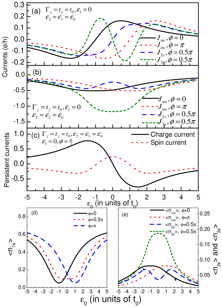
One of the well-known characteristics of QD is its tunable level via the adjustment of gate voltage in experiment. So, it is necessary for us to pay attention to the behaviors of the currents with the change of QD levels. In order to especially observe the spin accumulation of QD-1, is fixed at zero, but the levels of the other QDs are taken to be , which can be shifted by tuning the gate voltage. The profiles of the relevant quantities as functions of are plotted, and the corresponding results are exhibited in Fig.2, where, for simplicity, the many-body terms are ignored. We can readily find, in Fig.2(a) that, similar to the results in Fig.1, for the case of the charge currents in the two drains are the same as each other. But the shift of gate voltage can effectively change the directions of the charge currents, namely, in the absence of magnetic flux when exceeds the position of , the direction of the charge currents in the drains will be inverted, whereas when such a point is shifted to the position of . However, when the magnetic flux is tuned to , the profiles of the charge currents are separate from each other with their remarkable differences, though both of them are asymmetric about the point of . In Fig.2(b) we show the spectra of the spin currents in the drains, as a result, it is seen that the symmetric points of the spin currents just correspond to the anti-symmetric points of the charge currents and at these positions the spin currents present their exterma, respectively. Consider the case of , the spectra of persistent charge and spin currents are shown in Fig.2(c). It is clear that when goes beyond the zero point of the energy the direction of the persistent charge current is inverted, but with respect to the persistent spin current, its spectrum is just symmetric about the position of where the maximum of its amplitude emerges. In Fig.2(d) and Fig.2(e), we turn our attention to the spin accumulation in respective QDs. Associated with the results of the spin currents in Fig.2(b), it can be found that where there occurs the active spin transport are just the positions of the minimal spin accumulation in QD-1 in despite of its fixed level, but meanwhile in such regions in the other QDs the spin accumulations reaches their maxima (Here is considered to denote the spin accumulations in the respective QDs).
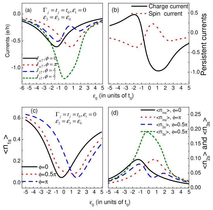
It is interesting that when a charge bias in introduced with , only the spin-up electron in the source can flow through this structure to the drains, and in such a case the spin current is just the charge current. Accordingly, in Fig.3 we show the spin-up electron properties driven by the charge and spin bias. It is seen that only the amplitude of the current can be adjusted by the tuning of magnetic flux or the shift of gate voltage, and in the case of the spin polarization in lead-3 is more apparent than that in lead-2. On the other hand, the application of charge bias influences the persistent currents in a nontrivial way. In such a case, the persistent charge current is apt to rotate along the negative direction, because of the left shift of the position where the direction of the persistent charge current inverts and the increase of the amplitude of the persistent charge current in the negative direction. This brings about the reversal of the direction of the pure persistent spin current, in comparison with that in the case of zero charge bias. Simultaneously, as shown in Fig.3(c) and (d), the extrema of the spin accumulations in respective QDs well coincide with the results in Fig.3(a).
In conclusion, we have discussed the electron transport through a triple-quantum-dot ring of three terminals. We found that despite the absence of the charge bias between the electrodes, in the drain electrodes there appear distinct charge and spin currents driven by the spin bias in the source electrode. Besides, in such a QD ring the persistent charge and spin currents driven by the spin bias are also remarkable and the directions and amplitudes of them can be adjusted by altering the structure parameters. On the other hand, the application of a finite charge bias between the source and drains of this structure can lead to the single-spin electron transmission. With respect to the many-body terms, we have to point out that the influence of the Coulomb repulsion on the electron transport is to divide the electron transport spectra into two groups, and in each group the results are similar to that in the noninteracting case. However, based on our calculated results, the amplitudes of the currents are correspondingly suppressed compared with those in the case of zero electron interactions, which can be clarified by the fact that the Coulomb repulsion reflects the localization of electrons.
References
- (1) Y. Ohno, D. K. Young, B. Beschoten, , Nature, 402, 790 (1999).
- (2) Zutic, J. Fabian, and S. Das Sarma, Rev. Mod. Phys. 76, 323 (2004); R. Hanson, L. P. Kouwenhoven, J. R. Petta, S. Tarucha, and L. M. K. Vandersypen, Rev. Mod. Phys. 79, 1217 (2004); S. A. Wolf, ., Science 294, 1488 (2001).
- (3) D. Loss and D. P. DiVincenzo, Phys. Rev. A 57, 120 (1998); G. Burkard, D. Loss, and D. P. DiVincenzo, Phys. Rev. B 63, 2070 (1999).
- (4) D. V. Bulaev and D. Loss, Phys. Rev. B 71, 205324 (2005).
- (5) A. A. Kiselev and K. W. Kim, Appl. Phys. Lett. 78, 775 (2001); T. P. Pareek, Phys. Rev. Lett. 92, 076601 (2004).
- (6) J. Nitta, T. Akazaki, H. Takayanagi, and T. Enoki, Phys. Rev. Lett. 78, 1335 (1997).
- (7) G. Engels, J. Lange, Th. Schäpers, and H. Lüth, Phys. Rev. B 55, R1958 (1997); D. Grundler, Phys. Rev. Lett. 84, 6074 (2000).
- (8) Q. F. Sun, J. Wang, and H. Guo, Phys. Rev. B 71, 165310 (2005); B. K. Nikolic and S. Souma, Phys. Rev. B 71, 195328 (2005).
- (9) A. Brataas, Y. Tserkovnyak, G. E. W. Bauer and B. I. Halperin, Phys. Rev. B 66, 060404 (2002); S. O. Valenzuela and M. Tinkham, Nature (London) 442, 176 (2006); Y. K. Kato, R. C. Myers, A. C. Gossard and D. D. Awschalom, Science 306, 1910 (2004); S. D. Ganichev, et al., Nature Physics 2, 609 (2006).
- (10) J. Hubner, et al., Phys. Rev. Lett., 90, 216601 (2003); Martin J. Stevens et al., Phys. Rev. Lett, 90, 136603 (2003)
- (11) X.-D. Cui, S.-Q. Shen, J. Li, Y. Ji, W. Ge, and F.-C. Zhang, Appl. Phys. Lett. 90, 242115 (2007).
- (12) J. Li and S. Q. Shen, Phys. Rev. B 76, 153302 (2007); P. Zhang, Q. K. Xue, and X. C. Xie, Phys. Rev. Lett. 91, 196602 (2003).
- (13) H. Katsura,J. Phys. Soc. Jpn. 76, 054710 (2007); Y.-J. Bao, N.-H. Tong, Q.-F. Sun, and S.-Q. Shen, Europhys. Lett. 83, 37007 (2008).
- (14) Y. Meir and N. S. Wingreen, Phys. Rev. Lett. 68, 2512 (1992); A.-P. Jauho, N. S. Wingreen, and Y. Meir, Phys. Rev. B 50, 5528 (1994).
- (15) W. Gong, Y. Zheng, Y. Liu, and T. Lü, Phys. Rev. B 73, 245329 (2006).
- (16) Y. Hancock, J. Suorsa,1 E. Tölö, and A. Harju, Phys. Rev. B 73, 245329 (2006); G.-H. Ding and B. Dong, Phys. Rev. B 76, 125301 (2007).