Probing punctual magnetic singularities during magnetization process in FePd films
Abstract
We report the use of Lorentz microscopy to observe the domain wall structure during the magnetization process in FePd thin foils. We have focused on the magnetic structure of domain walls of bubble-shaped magnetic domains near saturation. Regions are found along the domain walls where the magnetization abruptly reverses. Multiscale magnetic simulations shown that these regions are vertical Bloch lines (VBL) and the different bubble shapes observed are then related to the inner structure of the VBLs. We were thus able to probe the presence of magnetic singularities as small as Bloch points in the inner magnetization of the domain walls.
It has been shown that alloys with perpendicular magnetic anisotropy (PMA) are good candidates for applications in new recording media with high density storage capacity or in magneto-logical devices Weller et al. (2000). Recently such materials, namely iron palladium (FePd) alloys have been used in spin-valves where they act as the polarizer and the free layer Seki et al. (2006). These devices are believed to work through the nucleation of a reversed domain followed by the propagation of a domain wall Seki et al. (2008). Numerous studies have advanced the knowledge of the magnetic configuration of FePd alloys by means of MFM imaging Asenjo et al. (1999); Samson et al. (1999), X-ray scattering Mulazzi et al. (2004), or numerical simulations Toussaint et al. (2002). Moreover it has been shown recently that it is possible, using Lorentz Transmission Electron Microscopy (LTEM) to image the magnetic distribution in PMA thin foils at the domain wall scale Masseboeuf et al. (2008). This method enables quantitative information to be obtained with a spatial resolution below ten nanometers coupled to the opportunity of applying magnetic field during imaging. Here we show that it is also possible to probe the micromagnetic configuration inside the domain wall enabling the detection of defects smaller than the expected spatial resolution.
Along a domain wall one can find some regions where the chirality abruptly switches. The area where the magnetization reverses is called a Bloch line, which can be either horizontal or vertical. An horizontal Bloch line is parallel to the magnetization inside the domain wall while the vertical Bloch line is perpendicular to the magnetization. Domain walls in PMA materials are Bloch-like walls and the in-plane magnetization inside the domain wall can thus be oriented in one or the other direction of the wall plane and defines its chirality. We can thus expect some vertical Bloch lines in FePd delimiting two different chirality of the domain wall. Vertical Bloch lines were extensively studied in the 80s in garnets. Experimental Thiaville and Miltat (1990); Thiaville et al. (1991, 2001) and numerical Hubert (1974); Slonczewski (1975); Nakatani and Hayashi (1988); Miltat et al. (1989) approaches have helped us to understand these types of magnetic defects. Observations were possible using magneto-optical microscopy due to the large width of domain walls in garnets (). This large value has to be compared with the domain wall width in FePd of around 8 nm Masseboeuf et al. (2009), well below the resolution of optical methods. The simulation of the magnetic structure in garnets is also much easier than for FePd. Indeed, in garnets the very high quality factor , where is the anisotropy constant and the saturation magnetization, enables local approximations for the computation of the demagnetizing field Slonczewski (1975). This assumption is a priori not valid in the case of FePd, which exhibits smaller values of in the order of 1.6.
The aim of this letter is to show that new magnetic modeling coupled to recent developments in LTEM enables the observation of such small magnetic defects as VBL in domain walls of less than 10 nm width. We focus in this work on VBL which are trapped in magnetic bubbles appearing in FePd thin foils near the saturation state.
A thin layer of L10-FePd (37 nm) has been deposited on a “soft” layer of chemically disordered FePd2 layer, grown on a MgO (001) substrate by Molecular Beam EpitaxyBeutier et al. (2004). The soft layer is used to enhance the recording efficiency in perpendicular recording hard drives (see for example the section 2.4 of Khizroev and Litvinov, 2004). The sample for LTEM has been then prepared using classical method by mechanical polishing and ion milling. The microscope used is a JEOL 3010 fitted in with a Gatan imaging filter for contrast enhancement by zero-loss filtering Dooley and De Graef (1997). The in-situ magnetization is performed with the objective lens while imaging is realized with the objective mini lens traditionally used for low magnification imaging. The field produced by the objective lens has been carefully calibrated by inserting a dedicated sample holder mounted with a Hall probe before the experiment.
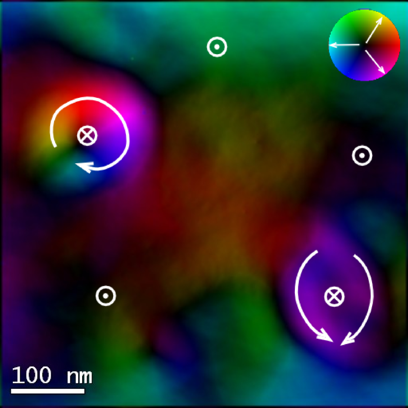
We measured the half hysteresis loop of the film in Fresnel mode Chapman (1984). For a field of 775 mT, just before the complete saturation of the magnetic layer, a focal series has been performed. The complete description of this magnetization process can be found elsewhereMasseboeuf et al. (2008). Fig. 1 shows the focal series reconstruction using the Transport-of-Intensity Equation Paganin and Nugent (1998). The magnetic information is originally mixed with an electrostatic contribution Aharonov and Bohm (1959) which has been removed by considering a constant variation of the thickness of the sample Masseboeuf et al. (2009). Due to the Lorentz force, the LTEM is sensitive to magnetic induction integrated along the electron beam direction in the TEM. However, assuming that stray fields on both side of the layer are antiparallel, the integrated induction may be considered approximately the same as the integrated magnetization. In the following we will discuss about simulation on integrated magnetization.
In Fig. 1 we can clearly see two types of magnetic bubbles. On the upper left corner one can see a magnetic bubble where the magnetization swirls continuously along the domain wall between the residual magnetic domain (indicated as down in Fig. 1) and the reversed domain. On the bottom right corner, one finds a magnetic bubble where the magnetization experiences two rotations of 180∘ resulting in two “different” domain walls pointing in similar directions.
At this point of the hysteresis loop a lot of bubbles are present in the film and both kinds of bubbles can be easily found. The two switching points observed in the second bubble type are supposed to be vertical Bloch lines (VBL)Hubert and Shäfer (1998). It must be noticed that the geometric deformation observed for the bubble with two VBL (the bubble showing a lemon shape) is fully reproducible.
In order to investigate the internal structure of these lines, we have performed magnetic simulations on bubbles with and without VBL. Due to the large range of scale needed to model these objects, we developed and used a multiscale efficient method. This method uses an adaptive mesh refinement technique to achieve both computational efficiency and numerical accuracy (details on the method can be found in Ref. Jourdan et al., 2008). This is particularly useful in the case of bubbles as the inner and outer part of the bubble can be loosely meshed, whereas the domain wall and the VBL must be densely meshedJourdan et al. (2009). Moreover, the code we used has the particularity to take into account the atomic structure of the material which is ignored in standard micromagnetic codes. The size of the micromagnetic mesh is then automatically adapted and switch to atomistic mode to keep a good precision when necessary. This ensures that all magnetic configuration is correct as the micromagnetic fundamental assumption of low spatial variations is fulfilled (see Jourdan, 2008 for more details and comparisons with traditional code) and at the same time decrease drastically the number of mesh (thus decreasing the calculation time). The following calculation would have cost 8 times more mesh with a traditional micromagnetic parallel code.
In these simulations the saturation magnetization is , the anisotropy constant is and the exchange stiffness constantGehanno et al. (1997) is . With these parameters the exchange length, . Two different thicknesses have been considered : 15 and 20.7 nm. In Fig. 2 the integrated magnetization along the thickness obtained from the simulations is shown for a bubble without VBL (A) and two bubbles with VBL for thicknesses of 15 (B) and 20.7 nm (C) in a field of 0.25 and 0.3 T respectively.
It can be seen that for a thickness of 15 nm (Fig. 2 B) the bubble is deformed in agreement with the LTEM observations, whereas for a thickness of 20.7 nm its shape remains circular (Fig. 2 C).
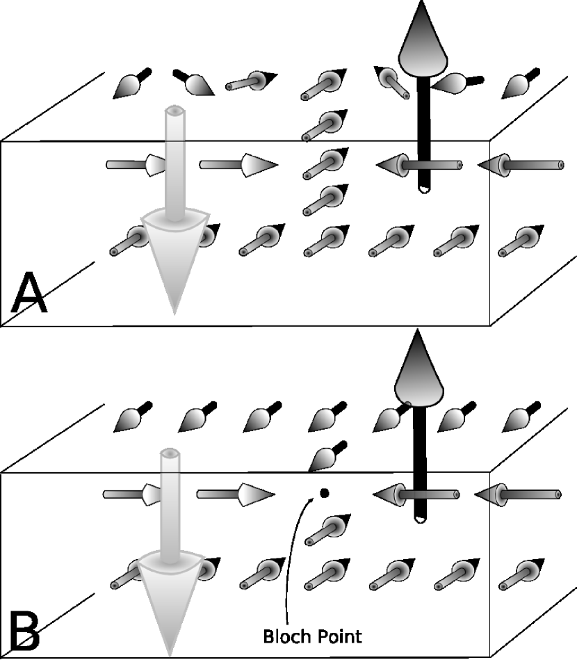
The modification of the shape can be explained by analysing precisely the structure of the VBL, depending of the thickness. Two kinds of VBL can thus be found. In the case of a small thickness, the magnetization is uniform along the VBL (Fig. 3 A), whereas it reverses along the VBL in the second case (large thickness), which leads to a magnetic singularity called a Bloch point (BP) (Fig. 3 B). The reason for the transition is a competition between the exchange and demagnetizing energies: the presence of a Bloch point leads to an increase in the exchange energy, whereas the demagnetizing energy decreases because the magnetization in the two segments of the line is aligned along the stray field generated by the domains.
Such a transition as a function of the thickness, has been reported by Hubert to be with an analytical model for a straight domain wallHubert (1976). According to our simulations for the particular geometry considered here, the transition is found between 4.5 and 6.3 . Given the thickness, of the films observed by LTEM, the VBL should contain a Bloch point, which is not consistent with the deformed states observed. However, the soft layer under the L10 FePd film changes the magnetic configuration and alters the respective contributions of the exchange and demagnetizing terms to the energy. As described in a previous articleMasseboeuf et al. (2007), the main role of the soft layer on the domain wall is an enhancement of the size (and as a consequence, the thickness) of the bottom Néel cap of the Bloch walls. This vertical dissymmetry could thus favours the configuration with no BP by increasing the dipolar energy.
The deformation observed in the absence of a BP gives rise to a reduction of magnetic chargesJourdan et al. (2009): it is analogous to the small buckling of the magnetization identified in straight domain walls in garnetsMiltat et al. (1989). In these materials, the buckling reduces the so-called “dipolar” charges which are related to the variation of the magnetization perpendicular to the domain wall. In the case of FePd, the lower quality factor, reduces the lateral extension of the VBL, which leads to large “monopolar” charges. A far larger buckling than could be expected following the studies on garnets is obtained, beside a reduction of charges, it also reduces charges by a compensation of these two types of charges. It is worthy to note that the magnetization is oriented in the same direction in both VBL, so that the 360∘-like domain walls are located on opposite surfaces. To compensate these charges, a different orientation in the VBL would lead to a “heart”-shape bubble, which is not found to be stable in our simulations.
To conclude, in this letter we have highlighted the very high resolution obtained by combining Lorentz Transmission Electron Microscopy and multiscale simulations. The resolution we achieved by conventional electron microscopy enables us to probe magnetic singularities well below the LTEM spatial resolution. Furthermore a main advantage of the multiscale code was its rapidity and its low memory requirements. In that particular case we decrease the number cells thanks to a factor 8 regarding traditional parallel code. The successful comparison of the two methods shown that it is possible to determine the inner magnetic configuration of a VBL, namely the presence or the absence of Bloch points in them.
References
- Weller et al. (2000) D. Weller, A. Moser, L. Folks, M. E. Best, W. Lee, M. Toney, M. Schwickert, J.-U. Thiele, and M. Doerner, IEEE Transaction on Magnetics 36, 10 (2000).
- Seki et al. (2006) T. Seki, S. Mitani, K. Yakushiji, and K. Takanashi, Applied Physics Letters 88, 172504 (pages 3) (2006).
- Seki et al. (2008) T. Seki, S. Mitani, and K. Takanashi, Physical Review B (Condensed Matter and Materials Physics) 77, 214414 (pages 8) (2008).
- Asenjo et al. (1999) A. Asenjo, J. Garcia, D. Garcia, A. Hernando, M. Vazquez, P. Caro, D. Ravelosona, A. Cebollada, and F. Briones, Journal of Magnetism and Magnetic Materials 196, 23 (1999), ISSN 0304-8853, 7th European Magnetic Materials and Applications Conference (EMMA 98), ZARAGOZA, SPAIN, SEP 09-12, 1998.
- Samson et al. (1999) Y. Samson, A. Marty, R. Hoffmann, V. Gehanno, and B. Gilles, in J. Appl. Phys. (AIP, 1999), vol. 85, pp. 4604–4606.
- Mulazzi et al. (2004) M. Mulazzi, K. Chesnel, A. Marty, G. Asti, M. Ghidini, M. Solzi, M. Belakhovsky, N. Jaouen, J. M. Tonnerre, and F. Sirotti, Journal of Magnetism and Magnetic Materials 272-276, E895 (2004), proceedings of the International Conference on Magnetism (ICM 2003).
- Toussaint et al. (2002) J. C. Toussaint, A. Marty, N. Vukadinovic, J. B. Youssef, and M. Labrune, Computational Materials Science 24, 175 (2002).
- Masseboeuf et al. (2008) A. Masseboeuf, C. Gatel, A. Marty, J. C. Toussaint, and P. Bayle-Guillemaud, in Journal of physics: conference series (Institute of Physics Publishing, 2008), vol. 126, p. 012055.
- Thiaville and Miltat (1990) A. Thiaville and J. Miltat, Journal of Applied Physics 68, 2883 (1990).
- Thiaville et al. (1991) A. Thiaville, J. B. Youssef, Y. Nakatani, and J. Miltat, 35th annual conference on magnetism and magnetic materials 69, 6090 (1991).
- Thiaville et al. (2001) A. Thiaville, J. Miltat, and J. Ben Youssef, European Physical Journal B 23, 37 (2001).
- Hubert (1974) A. Hubert, AIP Conference Proceedings 18, 178 (1974).
- Slonczewski (1975) J. C. Slonczewski, AIP Conference Proceedings 24, 613 (1975).
- Nakatani and Hayashi (1988) Y. Nakatani and N. Hayashi, Magnetics, IEEE Transactions on 24, 3039 (1988).
- Miltat et al. (1989) J. Miltat, A. Thiaville, and P. Trouilloud, Journal of Magnetism and Magnetic Materials 82, 297 (1989).
- Masseboeuf et al. (2009) A. Masseboeuf, C. Gatel, J. C. Toussaint, A. Marty, and P. Bayle-Guillemaud, Ultramicroscopy In press, doi:10.1016/j.ultramic.2009.08.006 (2009).
- Beutier et al. (2004) G. Beutier, A. Marty, K. Chesnel, M. Belakhovsky, J. Toussaint, B. Gilles, G. Van der Laan, S. Collins, and E. Dudzik, Physica B 345, 143 (2004).
- Khizroev and Litvinov (2004) S. Khizroev and D. Litvinov, Perpendicular Magnetic Recording (Kluwer Academic Publishers, 2004).
- Dooley and De Graef (1997) J. Dooley and M. De Graef, Micron 28, 371 (1997).
- Chapman (1984) J. Chapman, Journal of Physics D : Applied Physics 17, 623 (1984).
- Paganin and Nugent (1998) D. Paganin and K. Nugent, Physical review letters 80, 2586 (1998).
- Aharonov and Bohm (1959) Y. Aharonov and D. Bohm, Physical Review 115, 485 (1959).
- Hubert and Shäfer (1998) A. Hubert and R. Shäfer, Magnetic Domains (Springer, 1998).
- Jourdan et al. (2008) T. Jourdan, A. Marty, and F. Lançon, Physical Review B 77, 224428 (2008).
- Jourdan et al. (2009) T. Jourdan, A. Masseboeuf, F. Lançon, P. Bayle-Guillemaud, and A. Marty, submitted to Journal of Applied Physics (2009).
- Jourdan (2008) T. Jourdan, Ph.D. thesis, Universit Joseph Fourier (2008).
- Gehanno et al. (1997) V. Gehanno, A. Marty, B. Gilles, and Y. Samson, Physical Review B 55, 12552 (1997).
- Hubert (1976) A. Hubert, Journal ofMagnetism andMagneticMaterials 2, 25 (1976).
- Masseboeuf et al. (2007) A. Masseboeuf, F. Cheynis, J. C. Toussaint, O. Fruchart, C. Gatel, A. Marty, and P. Bayle-Guillemaud, in Materials Research Society Symposium Proceedings (2007), vol. 1026, pp. 1026–C22.