Current–phase relation in Josephson junction coupled with a magnetic dot
Abstract
The current-phase relation for a short Josephson junction placed in the nonuniform field of a small ferromagnetic particle is studied. The effect of the particle produced on the junction appears to be strong due to the formation of the pair of oppositely directed Abrikosov vortices which pierce the thin film superconducting electrode and cause a small–scale inhomogeneity of Josephson phase difference. The induced phase difference inhomogeneity is shown to result in the nonzero fixed phase drop across the junction. The equilibrium value corresponding to the ground state of the junction depends the configuration of the vortex–antivortex pair. The possibility to tune the ground state phase difference is discussed.
pacs:
Valid PACS appear hereI Introduction
Usually the current–phase relation (CPR) in Josephson junction close to the critical temperature is sinusoidal , and the dependence of the free energy assumes positive values of the critical current (see Ref. Golubov-RMP04, ). So, in the absence of a supercurrent, , the phase drop across the conventional junction equals zero Josephson-PL62 . But under certain conditions one can fabricate so-called Josephson junction Bulaevskii-JETPL77 which has an energy minimum at , i.e., it provides a phase shift of in the ground state (Refs. Golubov-RMP04, ; Buzdin-RMP05, ). The CPR of junctions reads and can be formally described by the negative value of the critical current . The states have been observed in Josephson junctions consisting of two wave superconductors Tsuei:00 in superconductor/ferromagnet/superconductor (SFS) junctions utilizing ferromagnetic barriers Ryazanov-PRL01 ; Kontos-PRL02 ; Blum-PRL02 , and also in multiterminal superconductor/normal-metal/superconductor (SNS) Josephson junctions Baselmans-Nature00 . Such junctions are supposed to open up new opportunities for designing Josephson effect–based devices Ioffe-Nature99 ; Yamashita-PRL05 ; Ustinov-JAP03 .
Recently the investigations of Josephson junctions which provide the realization of an unusual current–phase relation
| (1) |
have been attracting a lot of attention Buzdin-PRB03 ; Goldobin-PRB07 ; Buzdin-PRL08 . The minimum of the Josephson energy of junctions corresponds to the nonzero value of the phase difference such as . The realization of the junction is possible in the case of periodic structures composed of alternating and mini–junctions Buzdin-PRB03 ; Goldobin-PRB07 , or in the case of SNS structures when the normal layer is a noncentrosymmetric magnetic metal Buzdin-PRL08 . Josephson junctions demonstrate unusual properties and may serve as phase shifters in the superconducting (SC) electronics circuits Terzioglu-ASC98 .
The junctions described above utilize an intrinsic phase change due to the peculiarities of tunneling through the ferromagnetic layer or/and superconducting wavefunction symmetry. An alternative approach is to produce a phase shift across the junction using flux- or current–biasing. Examples are tools based on trapping fluxoids in a mesoscopic ring incorporated into dc-SQUID Majer-APL02 or Josephson junction with the additional current injector–extractor pair which creates an arbitrary discontinuity of the Josephson phase difference Ustinov-APL02 ; Goldobin-PRL04 . Here we suggest to use small ferromagnetic particles to create the phase–biased Josephson system. An arbitrary phase drop across the junction is shown to be caused by a small–scale phase difference inhomogeneity induced by the particle.
Let us briefly remind of the basic mechanisms which could provide a strong phase variation along the contact on a scale which is smaller than the Josephson penetration depth. First of all, the natural source of a phase inhomogeneity is an Abrikosov vortex (AV) pinned in the SC electrodes. Even a single misaligned AV, trapped in the SC electrodes perpendicular to the junction plane, is known to modify strongly the critical current and the current–voltage characteristics of Josephson junctions Uchida-JAP83 ; Miller-PRB85 ; Golubov-JETP87 ; Ustinov-PRB93 ; Fistul-PRB98 . Next, discontinuities in the phase difference along the barrier appear in a Josephson junction composed of alternating and mini-junctions Mints-PRB97 (the zigzag junctions between high- and conventional superconductors Smilde-PRL02 as well as SFS junctions with a steplike thickness of the ferromagnetic interlayer Goldobin-PRL06 ). Finally, arbitrary phase inhomogeneity can be formed with a current injection into Josephson junction on a scale smaller than the characteristic Josephson length Ustinov-APL02 ; Goldobin-PRL04 . The presence of such phase singularities results in the unusual CPR Buzdin-PRB03 , an anomalous non-Fraunhofer dependence Smilde-PRL02 , and spontaneous generation of fractional Josephson vortices at the boundaries between and regions Mints-PRB98 ; Mints-PRL02 .
Another method for creating of a controlled phase inhomogeneity in Josephson junctions has been proposed and successfully realized recently. This method is based on the interaction of a Josephson contact with the nonuniform magnetic field of submicron ferromagnetic particles located close to the junction Aladyshkin-JMMM03 ; Vdovichev-JETPL04 ; Fraerman-PRB06 . These experiments have demonstrated a essential dependence of the critical current on the magnetic state of the particles. This means that the transport properties of Josephson contacts can be effectively controlled by the magnetic field of the small particles. Experimentally detected additional maxima in the field dependence of the critical current have unambiguously indicated commensurability effects between a periodic distribution of the Josephson phase difference created by the particles and the scale of the phase modulation induced by an applied magnetic field Fraerman-PRB06 ; Samokhvalov-JETP07 . While the macroscopic commensurability effects have already been demonstrated in such hybrid ferromagnet–superconductor (FS) systems, the insight into the current–phase relation is still lacking.
In this paper we study theoretically the hybrid FS system consisting of a Josephson junction coupled with a single magnetic dot as it is shown in Fig.1. We demonstrate that the phase shift in the ground state of the Josephson junction depends on the magnetic state of the particle. We discuss the possibility to realize of Josephson -junction based on such hybrid FS structure. The paper is organized as follows. In Sec.II, we introduce a model used to explain the appearance of a nonuniform phase–difference distribution in Josephson junction coupled with a magnetic dot. In Sec.III, we study the ground state of this hybrid system which is characterized by the finite phase difference drop across the junction. In Section IV we summarize our results.
II Josephson phase modulation induced by a magnetic particle
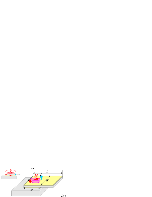
We consider a generic example of the FS hybrid system consisting of a short square () Josephson junction and an elongated magnetic particle on its top electrode. The junction is formed by overlapping two long SC strips () of thickness (top) and (bottom) as shown in Fig.1a. The single-domain magnetic dot with in-plane magnetization is separated from the top SC electrode by a thin insulating layer, which prevents the proximity effect. The interaction between the junction and the particle may be provided by the magnetic field generated by the dot and supercurrents. For the sake of simplicity, we consider here only the case of a rather small junction with
| (2) |
where and are the London penetration depth and the Josephson penetration depth, respectively, and is the thin–film screening length. The gauge invariant phase difference across the junction is given by the expression
| (3) |
Here and are distributions of the phase of Cooper wave function in the bottom and the top SC electrodes, respectively, is a vector in the junction plane, is the normal to the junction plane component of the magnetic vector potential , and - is the flux quantum. In a thin SC strip with , the self–field of the sheet current can be disregarded, and the top electrode is assumed to be transparent to the magnetic field of the particle. In its turn, this magnetic field partially penetrates into the bottom superconductor and induces in-plane screening Meissner currents in it. Since the top film thickness is assumed to be small it is reasonable to apply the gauge to avoid the strong singularity of the vector potential in the limit . For this gauge the phase difference across the junction (3) is determined by the distributions and of the phase of the wave functions only.
In the absence of vortex lines trapped in the electrodes the ground state of the system can be described by the uniform phase and screening Meissner currents are determined by the the in-plane component of the vector potential . So, the gauge invariant phase difference (3) across the junction equals zero: , and the magnetic field of the particle does not modify the critical current of the Josephson junction.
Vortex (antivortex), if appears, must be located near the negative (positive) pole of the magnetic dot VanBael-PRL01 , as shown in Fig. 1a. According to the concept proposed in Ref.Fraerman-PRB06, , a pair of vortices of opposite directions pierce the top electrode of the junction. As before, we put due to the absence of vortex lines in the bottom electrode. Suppose that the pair size (i.e., the vortex–antivortex distance) is rather large compared with the superconducting coherence length , then the electrodynamic mechanism based on the spatial dependence of the gauge invariant phase difference
| (4) |
is dominant Miller-PRB85 ; Golubov-JETP87 . Here and are the vortex and antivortex positions, respectively.
II.1 Basic equations
As a next step we should find the phase difference distribution over the junction area. The small size of the junction means that self–field effects of the Josephson current can be neglected compared to the in-plane currents. In this case, the phase-difference distribution obeys the two-dimensional Laplace equation Barone:Joseph ; Barone-JAP82 :
| (5) |
In the presence of trapped Abrikosov vortices the top electrode of the Josephson contact becomes a multiply connected domain. So, it is necessary to take into account the topological singularities of the phase distribution which are caused by presence of the vortex–antivortex pair Bulaevskii-PRB92 . According to the Eq. (4) we obtain the following condition for :
| (6) |
which fixes the circulation around the singularities.
For , the in-plane sheet current density in the top electrode
| (7) |
is determined mainly by the phase gradient induced by the trapped vortices rather than the vector potential . Indeed, the term with in the Eq. (7) is of the order of and can be neglected. It means that the sheet current density (7) is determined by the gauge invariant phase difference : . At the edges of the top stripe ( ; ) the normal component of the sheet current vanishes, and the Eq. (5) must be supplemented with the following boundary conditions:
| (8) |
Finally, a local phase inhomogeneity due to the presence of a vortex–antivortex pair has to vanish at distances larger as compared with the pair size . For the sake of simplicity the top electrode is assumed to be a semi–infinite SC strip, and the condition
| (9) |
has to be satisfied. Thus, the equations (5),(6) and the boundary conditions (8),(9) describe the phase difference distribution which is induced by a vortex–antivortex pair trapped in the top electrode of the contact.
At a constant value of the critical current density and the standard sinusoidal form of CPR the ground state of this junction in the absence of a supercurrent corresponds to a minimum of the Josephson energy
| (10) |
where the integral is evaluated over the junction area , and . The current–phase relation for the junction
| (11) |
reveals the shift which depends on the phase difference distribution .
By minimizing the Josephson energy (10) with respect to one can find the equilibrium distribution of the gauge invariant phase difference for the junction containing the vortex–antivortex pair, where the additive constant
| (12) |
determines the fixed phase shift between the top and bottom electrodes away from the junction area. The coefficients and in (12) depend on the distribution of the phase difference induced by the trapped Abrikosov vortices:
| (13) |
Varying the magnetic state of the particle one may control changing the vortex(antivortex) position, and, thereby, tune the average phase difference across the junction.
II.2 Phase Difference Distribution
The the gauge invariant phase difference due to the presence of a single vortex–antivortex pair trapped in the top electrode can be calculated as follows. First of all, let’s neglect the edge effects (8). The distribution , which satisfies the Laplace equation (5) and provides for the required phase circulation (6) around the singularities , can be written as a superposition of contributions from two point opposite vortices:
| (14) |
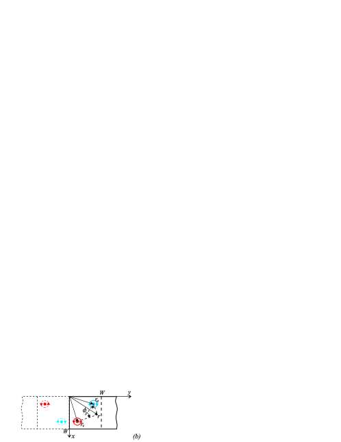
The phase of the wave function describing a point vortex (antivortex) is determined by the polar angle specifying the direction from the position of the vortex axis to the reference point (see Fig. 1b):
| (15) |
It is evident that for and, thus, the distribution (14),(15) satisfies the condition (9). Figure 2 illustrates schematically the distribution of the phase difference created by a pair of opposite vortices. The dark central area between the vortices shows the region where and . This domain provides with an additional positive contribution to the Josephson energy (10) and, as a consequence, such state of the junction appears to be an energetically unfavourable. The energy excess associated with the pair presence grows as the intervortex distance increases.
To take into account the boundary conditions (8) the solution may be written in the following convenient form:
| (16) |
Here is the phase distribution created by the vortice images (see Fig. 1b)
| (17) |
and is the solution of the Laplace equation
| (18) |
in the infinite stripe ( , ) with the following boundary conditions at the stripe edges and
| (19) |
where
The expressions (14)-(17),(II.2) determine the distribution of the gauge invariant phase difference created by the pair of opposite point vortices trapped in the thin top electrode of the Josephson junction. This phase distribution is used to calculate the Josephson energy (10) and the total current through the contact (11) for different positions of vortex and antivortex.
III Ground state of Josephson junction coupled with a magnetic particle
Now we proceed with the calculations of the ground state of the Josephson junction which depends on the size and orientation of the vortex–antivortex pair induced by the magnetic particle. We restrict ourselves to the case of zero homogeneous external magnetic field. For simplicity, the vortex and antivortex are assumed to be placed symmetrically with respect to the center of the junction :
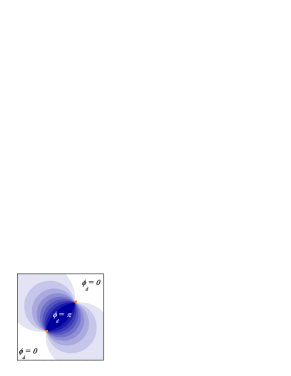
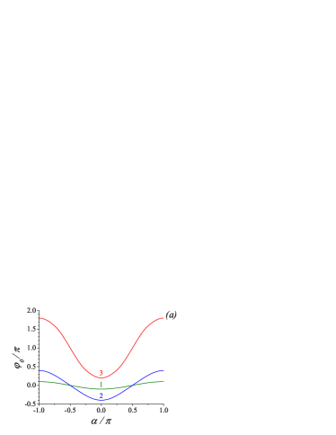
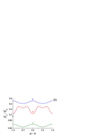
Figures 3 shows the dependence of the average phase difference (12) and the Josephson energy (10) on the location of the vortices. As an example we consider the change in the phase due to the rotation of the vortex–antivortex pair with respect to the midpoint . In this case the location of the vortices is determined by the intervortex distance and the angle of the pair rotation
relative to the direction of -axis (see Fig. 1). The range of the change in depends on the pair size . For (Fig. 3, curve 1) the phase inhomogeneity occupies a small part of the junction area, and the presence of the vortex–antivortex pair does not affect the junction properties essentially. The value of varies weakly round about the point , and the junction demonstrates mainly the properties of a conventional junction: the ground state corresponds to the almost zero phase drop across the junction. An increase in the pair size leads to forming a strong phase modulation , and the average phase difference can take practically any value between and in dependence on the angle (Fig. 3, curve 2). This is accompanied by the growth of the Josephson energy due to the expansion of the domain where . The further increase in the pair size () leads to the additional shift of the average phase difference (Fig. 3, curve 3), and the junction exhibits the switching into the new ground state which is specific for junctions: the value of oscillates about the point .
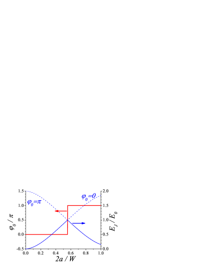
Figure 4 shows the dependences of the average phase difference and the Josephson energy of the ground state vs the intervortex distance for the fixed orientation of the vortex-antivortex pair . For a small intervortex distance , the domain, where the energetically unfavourable phase difference exists, occupies the central part of the junction. The size of the domain is small, and this part of the junction gives a small additional positive contribution to the Josephson energy . As a result, the conventional ground state realizes, which is described by the zero value of the average phase difference . The increase in the intervortex distance provokes an expansion of the energetically unfavourable domain, and, consequently, the rise in the Josephson energy of the state corresponding to a choice of . Let’s introduce the complementary phase difference distribution which differs from the initial one by the shift: . In the absence of trapped vortices the complementary state is unrealizable, since it corresponds to a maximum of the Josephson energy (10). The generation of the vortex-antivortex pair results in a decrease of the Josephson energy of the complementary state . The crossing of the curves and occurs at , so that the switch between the conventional state () and the shifted one () takes place. As a result, the ground state of the junction changes for sufficiently large intervortex distances . Certainly, the switching point depends on configuration of the vortex-antivortex pair. Such a crossover between and states manifests itself as a shift of the superconducting phase between the electrodes of the junction.
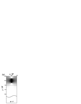
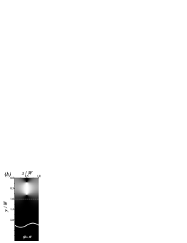
In Fig. 5 we present examples of the simulations of the equilibrium phase difference for the junction containing the vortex–antivortex pair. For a small intervortex distance (), the conventional ground state realizes (Fig. 5a). This state corresponds to the zero phase drop across the junction in the absence of a supercurrent. With the increase in the intervortex distance (), the additive phase shift decreases in part the Josephson energy corresponding the central domain between the vortices (Fig. 5b). As a result, there appears a shift in the phase of the superconducting order parameter across the junction.
IV Summary
In conclusion, we have studied theoretically the properties of the hybrid system consisting of a short Josephson junction located in a nonuniform field of the magnetic particle. The effect of the particle on the junction is shown to be strong due to the formation of the pair of oppositely directed Abrikosov vortices which pierce the top electrode of the junction. From an experimental point of view the vortex–antivortex pair can be created by cooling the junction through transition temperature in the dipole magnetic field of a magnetic dot VanBael-PRL01 . As a result, one should use single–domain magnetic dots with in–plain magnetization such as elongated submicron dots. For parameters of magnetic dots taken from the experiments, Fraerman-PRB06 (the saturation magnetization , lateral dimensions and a thickness of ) we can estimate typical dimension of the Josephson junction as . Magnetostatic calculations show that the stray field of both poles of the dot creates a (positive or negative) flux through the top SC electrode, and the criterion VanBael-PRL01 ; Milosevic-PRB04 for the nucleation of the vortex–antivortex pair is satisfied. Since the flux rapidly decreases when a distance between the magnetic dot and a superconductor becomes comparable with the lateral sizes of the dot, the Meissner state is more energetically favorable in the thick bottom electrode upon cooling through .
The vortex–antivortex pair trapped in the top electrode causes the inhomogeneity of the gauge invariant phase–difference on scales that are significantly smaller than the Josephson length. The pair size and orientation are determined by the size and magnetization of the particle. We have calculated the corresponding distribution of the Josephson phase difference over the junction and have studied the dependence of the Josephson energy on the vortex configuration. It was shown that the ground state of the junction corresponds to the nonzero drop of the average phase difference across the junction . The equilibrium value of the phase difference depends on the size and orientation of the vortex–antivortex pair, i.e. on the magnetic state of the particle. This demonstrates the possibility to realize the tunable current–phase relation by changing the magnetization of the particle. Finally, note that such hybrid FS system incorporated into a superconducting ring should induce spontaneous currents and may serve as a natural phase shifter in the superconducting electronic circuits.
Acknowledgements.
I would like to thank A. S. Mel’nikov for critical reading of the manuscript and for valuable suggestions. I am thankful to A. I. Buzdin and A. A. Fraerman for stimulating discussions. This work was supported, in part, by the Russian Foundation for Basic Research, and by the program ”Quantum Physics of Condensed Matter” of the Russian Academy of Sciences.References
- (1) A. A. Golubov, M. Yu. Kupriyanov, and E. Il’ichev, Rev. Mod. Phys. 76, 411 (2004).
- (2) B. D. Josephson, Phys. Lett. 1, 251 (1962).
- (3) L. N. Bulaevskii, V. V. Kuzii, and A. A. Sobyanin, Pis’ma Zh. Eksp. Teor. Phys. 25, 314 (1977) [JETP Lett. 25, 290 (1977)].
- (4) A. I. Buzdin, Rev. Mod. Phys. 77, 935 (2005).
- (5) C. C. Tsuei and J. R. Kirtley, Rev. Mod. Phys. 72, 969 (2000).
- (6) V. V. Ryazanov, V. A. Oboznov, A. Yu. Rusanov, A. V. Veretennikov, A. A. Golubov, and J. Aarts, Phys. Rev. Lett. 86, 2427 (2001).
- (7) T. Kontos, M. Aprili, J. Lesueur, F. Genet, B. Stephanidis, and R. Boursier, Phys. Rev. Lett. 89, 137007 (2002).
- (8) Y. Blum, A. Tsukernik, M. Karpovski, and A. Palevski, Phys. Rev. Lett. 89, 187004 (2002).
- (9) J. J. A. Baselmans, A. F. Morpurgo, B. J. van Wees, and T. M. Klapwijk, Nature (London) 397, 43 (1999).
- (10) L. B. Ioffe et al., M. V. Feigel’man, A. L. Fauchere G. Blatter, Nature (London) 398, 679 (1999).
- (11) T. Yamashita, K. Tanikawa, S. Takahashi, and S. Maekawa, Phys. Rev. Lett. 95, 097001 (2005).
- (12) A. V. Ustinov and V. K. Kaplunenko, J. Appl. Phys. 94, 5405 (2003).
- (13) A. I. Buzdin, A.E. Koshelev, Phys. Rev. B, 67, 220504(R) (2003).
- (14) S. M. Frolov and D. J. Van Harlingen, V. V. Bolginov, V. A. Oboznov, and V. V. Ryazanov, Phys. Rev. B 74, 020503 (2006); E. Goldobin, D. Koelle, R. Kleiner, and A. Buzdin, Phys. Rev. B, 76, 224523 (2007).
- (15) A. I. Buzdin, Phys. Rev. Lett, 101, 107005 (2008); A. A. Reynoso, G. Usaj, C. A. Balseiro, D. Feinberg, and M. Avignon, Phys. Rev. Lett., 101, 107001 (2008); A. Zazunov, R. Egger, T. Jonckheere, and T. Martin, Phys. Rev. Lett., 103, 147004 (2009).
- (16) E. Terzioglu and M. R. Beasley, IEEE Trans. Appl. Supercond. 8, 48 (1998).
- (17) J. B. Majer, J. R. Butcher, and J. E. Mooij, Appl. Phys. Lett. 80, 3638 (2002).
- (18) A. V. Ustinov, Appl. Phys. Lett. 80, 3153 (2002).
- (19) E. Goldobin, A. Sterck, T. Gaber, D. Koelle, and R. Kleiner, Phys. Rev. Lett. 92, 057005 (2004).
- (20) N. Uchida, K. Enpuku, Y. Matsugaki, S. Tomita, and F. Irie, J. Appl. Phys., 54, 5287 (1983).
- (21) S. L. Miller, K. R. Biagi, J. R. Clem, and D. K. Finnemore, Phys. Rev. B, 31, 2684 (1985).
- (22) A. A. Golubov, M. Yu. Kupriyanov, Zh. Exsp. Teor. Phys., 92, 1512 (1987); J. Low Temp.Phys. 70, 83 (1988).
- (23) A. V. Ustinov, T. Doderer, B. Mayer, and R. P. Huebener, A. A. Golubov, V. A. Oboznov, Phys. Rev. B, 47, 944 (1993);
- (24) M. V. Fistul, G. F. Giuliani, Phys. Rev. B, 58, 9348 (1998).
- (25) R. G. Mints and V. G. Kogan, Phys. Rev. B 55, R8682 (1997)
- (26) H.J.H. Smilde, Ariando, D. H. A. Blank, G. J. Gerritsma, H. Hilgenkamp, and H. Rogalla, Phys. Rev. Lett. 88, 057004 (2002).
- (27) M. Weides, M. Kemmler, H. Kohlstedt, R. Waser, D. Koelle, R. Kleiner, and E. Goldobin, Phys. Rev. Lett. 97, 247001 (2006).
- (28) R. G. Mints, Phys. Rev. B 57, R3221 (1998).
- (29) R. G. Mints and Ilya Papiashvili, J. R. Kirtley, H. Hilgenkamp, G. Hammerl and J. Mannhart, Phys. Rev. Lett. 89, 067004 (2002).
- (30) A. Y. Aladyshkin, A. A. Fraerman, S. A. Gusev, et al., J. Magn. Magn. Mater. 258-259, 406 (2003).
- (31) S. N. Vdovichev, B. A. Gribkov, S. A. Gusev, E. Il ichev, A. Yu. Klimov, Yu. N. Nozdrin, G. L. Pakhomov, V. V. Rogov, R. Stolz, and A. A. Fraerman Pis’ma Zh. Eksp. Teor. Fiz. 80, 758 (2004) [JETP Lett. 80, 651 (2004).
- (32) A.A. Fraerman, S. A. Gusev, Yu. N. Nozdrin, A. V. Samokhvalov, S. N. Vdovichev, L. Fritzsch, E. Il’ichev, and R. Stolz, Phys. Rev. B 73, 100503(R) (2006).
- (33) A. V. Samokhvalov, Zh. Eksp. Teor.Fiz. 131, 500 (2007) [Sov. Phys. JETP 104, 451 (2007).
- (34) M. J. Van Bael, J. Bekaert, K. Temst, L. Van Look, V. V. Moshchalkov, Y. Bruynseraede, G.D. Howells, A. N. Grigorenko, S. J. Bending, and G. Borghs, Phys. Rev. Lett. 86, 155 (2001).
- (35) A. Barone and G. Paterno, Physics and Application of the Josephson Effect, (Wiley,New York,1982).
- (36) A. Barone, F. Esposito, K. K. Likharev, V. K. Semenov, and B. N. Todorov, R. Vaglio, J. Appl. Phys. 53, 5802 (1982).
- (37) L. N. Bulaevskii, M. Ledvij, and V. G. Kogan, Phys. Rev. B 46, 366 (1992).
- (38) M. V. Milosevic, and F. M. Peeters, Phys. Rev. B,69, 104522 (2004).