Magnetic dipole moments in single and coupled split-ring resonators
Abstract
We examine the role of magnetic dipoles in single and coupled pairs of metallic split-ring resonators by numerically computing their magnitude and examining their relative contributions to the scattering cross section. We demonstrate that magnetic dipoles can strongly influence the scattering cross section along particular directions. It is also found that the magnetic dipole parallel to the incident magnetic field and/or high-order multipoles may play a significant role in the linear response of coupled split-ring resonators.
I Introduction
In a seminal paper published in 1999, Pendry et al. proposed that an array of metallic split-ring resonators (SRRs) can, in the long-wavelength approximation, possess an effective negative permeability at its inductor-capacitor resonance john1 . This proposal lead to the development of an artificial structured medium, a metamaterial, consisting of interspaced SRR and metallic rods which simultaneously displays negative permeability and permittivity smith . Such novel metamaterials are absent in nature and have potential application such as subwavelength or even perfect imaging john2 ; marques ; solymar . Metallic SRR arrays are a popular building block for metamaterials and have attracted intensive attention in the last decade marques ; solymar . Such arrays are sometimes referred to as magnetic metamaterials due to the significant role played by magnetic dipoles in their optical response.
Experimentally single- and multi- layered metallic single-slit SRR membranes have been fabricated and their optical responses are usually studied by measuring their transmission spectra at normal incidence linden ; liu ; gansel . A magnetic dipole moment perpendicular to the membrane, arising from a current circulating inside the SRR, is frequently mentioned as having a role in the observed transmission spectrum and in the coupling between adjacent SRRs liu ; liu2 ; schneider ; hesmer . However we propose that the role of this magnetic dipole is unclear or even over emphasized in the literature perhaps due to the difficulty in experimentally measuring magnetic dipoles. Furthermore, rarely mentioned is the contribution from a magnetic dipole parallel to the incident magnetic field arising from the strongly localized conduction electrons near the metallic surfaces jackson .
The main aim of this article is to clarify the role of these magnetic dipoles by numerically computing their magnitude and examining their relative contributions to the scattering cross section. To achieve our purposes, we simulate the optical response of an isolated single SRR and a coupled pair of SRRs using the finite-difference time-domain (FDTD) method taflove . Our numerical results show that the strength of the magnetic dipoles can be determined by measuring the scattering cross section along particular directions. We also note that in certain circumstances the magnetic dipole parallel to the membrane plays a significant role. For isolated pairs of coupled SRRs high-order multipoles contribute considerately to the scattering cross section. Finally we numerically verify the qualitative assumption in earlier literature liu that the magnetic dipole-dipole interaction must be considered to interpret the coupling strength between coupled SRRs.
The papers is arranged as follows. In Section II we show that in the presence of an electric dipole the analytical expression for a magnetic dipole is not translational invariant. In section III we numerically compute the various electric and magnetic dipole moments and present a quantitative analysis of their relative contributions to the scattering cross section. The role of magnetic dipoles and higher order multipoles in second harmonic generation from an individual SRR are studied in an appendix.
II Multipole theory in electromagnetic scattering and radiation
Let us first recall basic multipole theory in electromagnetic scattering and radiation jackson . For a localized current source , with sinusodial time dependence, the relevant vector potential at position is given by
| (1) |
where is the wave number, and the integration is performed over the current source. Its asymptotic form
| (2) |
can be achieved by approximating as in the denominator while in the numerator is replaced by with being the observation direction. Consequently, the far-zone electromagnetic fields can be formulated as
| (3) |
We can now write the time-averaged power scattered per unit solid angle as yong1
| (4) |
with being the intrinsic impedance of free space. In addition, according to the optical theorem the extinction power taken from an incident wave takes the form yang
| (5) |
This expression suggests that can be interpreted as interference between the incident wave and the forward scattering wave mishchenko .
The derivations above clearly demonstrate that the direction-dependent vector contains all the information for scattering and/or radiation. Using Taylor expansion, we can reformulate as
| (6) |
Mathematically this transformation is always valid, however, to achieve physically meaningful quantities the spatial dimensions of the current volume must be much smaller than the incident wavelength. In other words, the quantity should be small compared to unity, and consequently the successive terms in the expansion fall off rapidly with . The first term represents the electric dipole moment,
| (7) |
which corresponds to the electrostatic limit. The antisymmetric part of the second term is given by
| (8) |
with standing for the magnetic dipole moment, while the symmetric counterpart corresponds to electric quadrupole jackson .
Despite the fact that these definitions can be found from any popular undergraduate electromagnetism textbook, determining the electric and magnetic dipole of a realistic system is not straightforward. The main reason is that as long as exists is not translational invariant (independent of the choice of origin of coordinates). More specifically rewriting the above in a new coordinate system , which connects to the original as , we obtain an identical far-zone vector potential but a slightly different given by
| (9) |
In this new coordinate system the electric dipole is identical to that defined in Equation 7, however, the magnetic dipole must be reformulated as
| (10) |
The new formulation of the magnetic dipole depends on and is therefore not translationaly invariant, similarly for the high-order multipoles raab ; papasimakis . In order to compare the relative contributions of the magnetic dipoles to the linear scattering we therefore take the advantage of the structural symmetries by choosing the center of mass as the coordinate origin.
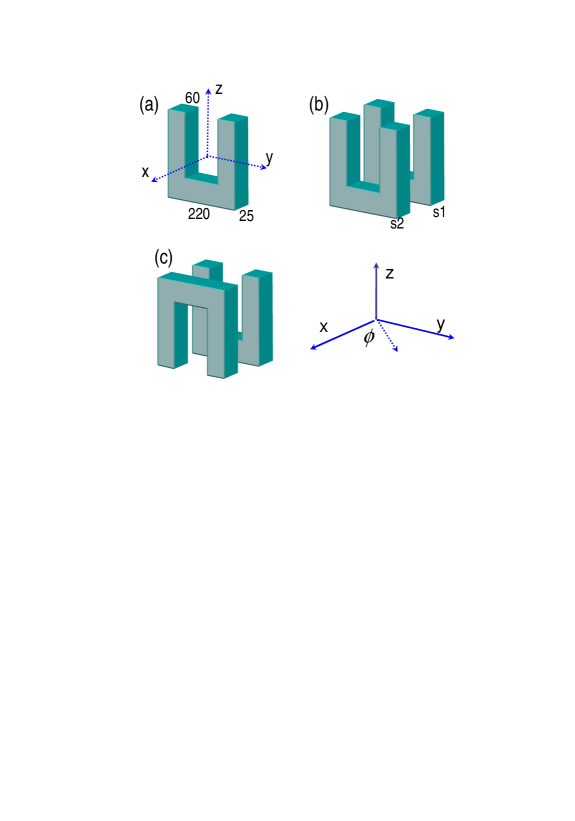
We apply this analysis to the configurations of gold SRRs embedded in vacuum as shown in Figure 1. The structures are excited by a -polarized plane wave propagating along the direction. It excites not only a -component electric dipole , but also a magnetic dipole possessing both and components. The component is due to the strongly localized conduction electrons of the metal, while is induced by the structural symmetry breaking. In order to simplify our analysis we ignore higher order multipoles and only consider contributions from the three dipoles , and .
From Equation 4 the scattering cross section along the three primary axes are given by
| (11) |
For example, along the direction the forward- or backward- scattering strength is influenced by the interference between the and dipoles, while the -component magnetic dipole does not contribute. This observation is at odds with the commonly stated assumption that the dipole plays a significant role in one valley of the transmission spectrum of SRR arrays where it is often referred to as the magnetic resonance linden . Similarly, along the direction the scattering cross section is due solely to the and dipoles and receives no contribution from the electric dipole . This observation may provide an insight on how to determine the relative magnitude of the various magnetic dipoles by experimentally measuring the scattering cross section along the orthogonal axes.
III Results and discussions
To quantify the relative contributions of the various electric and magnetic dipole moments we perform a numerical simulation of the structures shown in Figure 1 using the FDTD method. The relative dielectric constant of gold is fitted by the Drude model of
| (12) |
where s-1 is the bulk plasma frequency determined by the density of conduction electrons, s-1 represents the phenomenological damping rate palik . Using FDTD, with a center of mass coordinate system, we compute the polarization current inside the metallic structures and employ Equations 7 and 8 to determine the magnitude of the electric and magnetic dipole moments. Using Equations 4 and 5, which are independent of the chosen coordinate system, we compute the scattering and extinction cross sections yong1 .
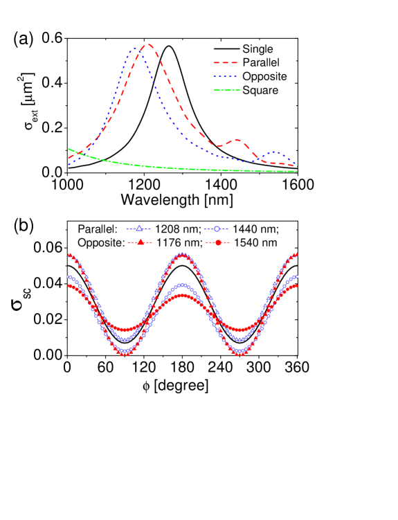
As before the structures are excited with a plane wave propagating along the positive direction and polarized in the direction. The absolute extinction cross section of the various SRR structures are shown in Figure (2a). For the single SRR (solid line) a peak corresponding to the fundamental plasmonic resonance was found at a wavelength of 1264 nm. A similar individual SRR is experimentally studied in Ref.husnik and the experimental extinction cross section and our numerical results are in excellent agreement. A periodic array of SRRs with lattice spacing of 305 nm was shown to have a fundamental resonance at 1212 nm wavelength, which is very close to the isolated SSR resonance indicating a weak coupling between adjacent SRRs yong3 .
The scattering cross section of the isolated SRR, at 1264 nm wavelength, as a function of the azimuthal angle in the plane is shown in Figure (2b) (solid line). This dependence curve can be fitted by which suggests that the linear scattering of this individual SRR is dominated by a -component electric dipole moment . Based on the analysis related to Equation 11 we can further estimate the magnitude of the magnetic dipoles from the scattering along the and directions. The plotted values of along directions are almost identical indicting a negligible -component magnetic dipole . Similarly for scattering along the directions the cross section is nonzero indicating the presence of a finite total magnetic dipole. Consequently we can deduce that the SRR possesses a considerable -component magnetic dipole .
To compare the relative strength of the numerically computed electric and magnetic dipole moments we normalize them to the electric dipole moment of the single SRR as follows
| (13) |
and the results are shown in Table 1. It is found that, for the individual SRR, while is almost zero, in agreement with the scattering-cross-section-based analysis above. For comparison we also plot in Figure (2a) the extinction cross section of a gold square of size nm. In the wavelength range of 1000 nm to 1600 nm the square exhibits no resonance peaks and has a weak extinction cross section consistent with its small normalized electric dipole of 0.23. However, it exhibits a larger -component magnetic dipole than the single SRR and, because of its symmetry, does not present a -component magnetic dipole .
We proceed to coupled SRRs oriented as depicted in Figure (1b,1c) with a separation between and of 30 nm. Two different configurations are studied. The two SRRs are parallel to each other in the first arrangement (named Parallel) while in the second arrangement s2 is rotated 180 degree in the plane (named Opposite). Their extinction spectra are shown in Figure (2a). For both configurations the 1264 nm peak of the individual SRR is split into two peaks induced by inter-SRR coupling. For the Parallel structure the peaks are located at 1208 nm and 1440 nm, and for the Opposite structure they are lactated at 1176 nm and 1540 nm. The larger separation between the peaks of the Opposite configuration indicates stronger inter-SRR coupling sakurai . Furthermore, for each structure the longer wavelength peak has a magnitude comparable to that of the individual SRR, while the shorter wavelength peak has significantly reduced extinction cross sections.
For each configuration the extinction cross section as a function of the angle in the plane is shown in Figure (2b). The scattering cross section along the direction indicates the strength of the total magnetic dipole moment. Along the direction the Parallel configuration at 1208 nm possesses a scattering cross section comparable to that of the single SRR. This is confirmed in Table 1 where is 0.25 and 0.26 for the single SRR and Parallel configuration, respectively. For the Opposite configuration at 1176 nm, however, scattering along the direction is almost zero indicating a negligible total magnetic dipole. This is also confirmed in the numerically computed values where is 0.008 and is an order of magnitude smaller than the single SRR with a value of 0.02.
The role of the component of the magnetic dipole can be determined by looking at the difference in scattering between the positive and negative directions. For example the Opposite configuration at 1540 nm has a relative scattering difference of 14% along these two directions. This difference is induced by interference between a -component electric dipole and a -component magnetic dipole . Consequently, we can infer that this structure possesses a significant -component magnetic dipole relative to the electric dipole. Again this is confirmed in Table 1 where the ratio of magnetic to electric dipole strength has a value of 0.23.
| Structure | Wavelength[nm] | |||
|---|---|---|---|---|
| Single | 1264 | 1 | ||
| Square | 1264 | 0.23 | 0 | 0.001 |
| Parallel | 1440 | 0.45 [1.65, -0.66] | 0.08 [1.93, -0.93] | 0.08 [0.68, 0.32] |
| Parallel | 1208 | 1.02 [0.54, 0.46] | 0.26 [0.56, 0.44] | 0.01 [4.3, -3.3] |
| Opposite | 1540 | 0.31 [2.06, -1.07] | 0.18 [0.58, 0.42] | 0.07 [0.63, 0.37] |
| Opposite | 1176 | 0.99 [0.53, 0.47] | 0.02 [9.1, -8.1] | 0.008 [4.9, -3.9] |
Higher order multipoles play a more profound role in the linear scattering of coupled SRRs since their effective thickness of 80 nm is much larger than 25 nm of a single SRR. At the shorter wavelength peaks both coupled configurations possess an electric dipole comparable to that of the single SRR, however, their scattering along the direction differ by 12%. Taking into account that is negligible for all three structures this difference cannot be interpreted by interference between the electric and magnetic dipoles alone. Consequently, contributions from higher-order multipoles, such as electric quadrupole, must be included. It should be mentioned that higher-order multipoles are also found to affect the optical properties of stereometamaterials liu .
To distinguish the relative contribution from each SRR in the coupled structures we compute their individual dipoles and normalize them to the total dipole moment. These values are listed in square brackets in Table 1 where values with opposite sign indicate the relevant dipoles are out of phase. For both Opposite and Parallel configurations the -component electric dipoles are in phase at the shorter wavelength peaks and out of phase at longer wavelength peaks. This is consistent with the fact that a coupled system possesses a high-energy symmetric mode as well as a lower-energy anti-symmetric mode. The inverse of this rule applies to the -component magnetic dipoles in that they are out of phase at shorter wavelengths and in phase at longer wavelengths due to the different symmetry of electric and magnetic fields. Because of the structural symmetry a more complicated phase relationship exists between the -component magnetic dipoles . For example, at the shorter-wavelength resonance they are in phase for the Parallel configuration while out of phase for the Opposite one. Table 1 further implies that although electric dipole-dipole interaction dominates the inter-SRR coupling, magnetic dipole-dipole interaction and in particular the interaction must be included to interpret the fact that the Opposite configuration presents a larger separation between resonance peaks than its counterpart.
IV Conclusions
This paper clarifies the role of magnetic dipoles in single and double metallic split-ring resonators (SRRs) by numerically computing their magnitudes and examining their relative contributions to the scattering cross section. We propose that the strength of the magnetic dipoles can be determined by measuring the scattering cross section along particular directions. It is demonstrated that the magnetic dipole parallel to the incident magnetic field plays a significant role for Opposite configuration at its longer wavelength resonance. Moreover, we found that for isolated pairs of coupled SRRs higher-order multipoles contribute considerately to the scattering cross section. By considering the relative phase between the partial dipoles possessed by individual SRRs, in coupled configurations, we have shown that the electric dipole-dipole interaction dominates the coupling between adjacent SRRs and also that the magnetic dipole-dipole interaction is responsible for the larger resonance separation in the Opposite configuration.
This work is supported by the Air Force Office of Scientific Research (AFOSR), under Grant No. FA9550-07-1-0010 and FA9550-04-1-0213. J. V. Moloney acknowledges support from the Alexander von Humboldt foundation.
V Appendix
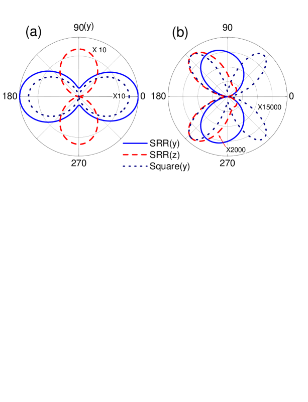
Using a recently developed classical theory yong2 , we numerically studied second-harmonic radiation from an individual SRR as schematically shown in Figure (1a). The fundamental plane wave propagates along the positive direction and has a wavelength of 1264 nm, corresponding to the fundamental resonances excited by a -polarized light. Its linear scattering cross section in the plane is shown in Figure (3a). For comparison we also considered a gold square of size nm. Its linear response is quite close to that of the SRR with a -polarized excitation, that is, they both possess an almost identical-strength electric dipole and a negligible magnetic dipole. The strongest electric dipole appears in the SRR with a -polarized excitation.
Figure (3b) plots second-harmonic radiation in the plane. Because of structural symmetry the gold square presents a dominant electric quadrupole pattern. On the other hand, magnetic dipoles are found to contribute considerably to the SRR with the -polarized excitation, and the radiation exhibits a slightly distorted dipole pattern. It is mainly due to the fact that the second-harmonic wavelength is around 600 nm while the lateral size of the SRR is roughly 200 nm. In addition, although the square has almost identical linear response as the SRR with -polarized excitation, its second-harmonic strength is much weaker. This is because its radiation is dominated by an electric quadrupole, while the SRR radiation is dominated by the electric and magnetic dipole.
References
- (1) J. B. Pendry, A. J. Holden, D. J. Robbins, and W. J. Stewart, “Magnetism from conductors and enhanced nonlinear phenomena”, IEEE Trans. Microwave Theory Tech. 47, 2075 (1999).
- (2) D. R. Smith, W. J. Padilla, D. C. Vier, S. C. Nemat-Nasser, and S. Schultz, “Composite Medium with Simultaneously Negative Permeability and Permittivity”, Phys. Rev. Lett. 84, 4184 (2000).
- (3) J. B. Pendry, “Negative refraction makes a perfect lens”, Phys. Rev. Lett. 85, 3966 (2000).
- (4) R. Marqués, F. Martín, and M. Sorolla, Metamaterials with negative parameters (Wiley, 2008).
- (5) L. Solymar and E. Shamonina, Waves in Metamaterials (Oxford University, 2009).
- (6) S. Linden, C. Enkrich, M. Wegener, J. Zhou, T. Koschny, and C. M. Soukoulis, “Magnetic Response of Metamaterials at 100 Terahertz”, Science 306, 1351 (2004).
- (7) N. Liu, H. Liu, S. Zhu, and H. Giessen, “Stereometamaterials”, Nature Photon. 3, 157 (2009).
- (8) J. K. Gansel, M. Thiel, M. S. Rill, M. Decker, K. Bade, V. Saile, G. von Freymann, S. Linden, and M. Wegener, “Gold Helix Photonic Metamaterial as Broadband Circular Polarizer”, Science 325, 1513 (2009).
- (9) N. Liu, S. Kaiser, and H. Giessen, “Magnetoinductive and electroinductive coupling in plasmonic metamaterial molecules”, Adv. Mater. 20, 4521 (2008).
- (10) A. Schneider, A. Shuvaev, S. Engelbrecht, S. O. Demokritov, and A. Pimenov, “Electrically Excited Inverse Electron Spin Resonance in a Split-Ring Metamaterial Resonator”, Phys. Rev. Lett. 103, 103907 (2009).
- (11) F. Hesmer, E. Tatartschuk, O. Zhuromskyy, A. A. Radkovskaya, M. Shamonin, T. Hao, C. J. Stevens, G. Faulkner, D. J. Edwards, and E. Shamonina, “Coupling mechanisms for split ring resonators: Theory and experiment”, phys. stat. sol. (b) 244, 1170 (2007).
- (12) J. D. Jackson, Classical Electrodynamics, 3rd Ed. (Wiley, 1999).
- (13) A. Taflove and S. C. Hagness, Computational Electrodynamics: the finite-difference time-domain method, 2nd Ed. (Artech House, 2000).
- (14) Y. Zeng and J. V. Moloney, “Polarization-current-based, finite-difference time-domain, near-to-far-field transformation”, Opt. Lett. 34, 1600 (2009).
- (15) P. Yang and K. N. Liou, “Finite-difference time domain method for light scattering by small ice crystals in three-dimensional space”, J. Opt. Soc. Am. A 13, 2072 (1996).
- (16) M. I. Mishchenko, “Radiation force caused by scattering, absorption, and emission of light by nonspherical particles”, J. Quant. Spectrosc. Radiat. Transf. 70, 811 (2001).
- (17) R. E. Raab and O. L. De Lange, Multipole theory in electromagnetism (Oxford University, 2005).
- (18) N. Papasimakis, V. A. Fedotov, K. Marinov, and N. I. Zheludev, “Gyrotropy of a Metamolecule: Wire on a Torus”, Phys. Rev. Lett. 103, 093901 (2009).
- (19) Handbook of optical constants of solids, edited by E. D. Palik (Academic, 1985).
- (20) M. Husnik, M. W. Klein, N. Feth, M. König, J. Niegemann, K. Busch, S. Linden, and M. Wegener, “Absolute extinction cross-section of individual magnetic split-ring resonators”, Nature Photon. 2, 614 (2008).
- (21) Y. Zeng and J. V. Moloney, “Volume electric dipole origin of second-harmonic generation from metallic membrane with noncentrosymmetric patterns”, Opt. Lett. 34, 2844 (2009)
- (22) J. J. Sakurai, Modern Quantum Mechanics, Revised Ed. (Addison-Wesley, 1994).
- (23) Y. Zeng, W. Hoyer, J. Liu, S. W. Koch, and J. V. Moloney, “Classical theory for second-harmonic generation from metallic nanoparticles”, Phys. Rev. B 79, 235109 (2009).