The entanglement beam splitter: a quantum-dot spin in a double-sided optical microcavity
Abstract
We propose an entanglement beam splitter (EBS) using a quantum-dot spin in a double-sided optical microcavity. In contrast to the conventional optical beam splitter, the EBS can directly split a photon-spin product state into two constituent entangled states via transmission and reflection with high fidelity and high efficiency (up to 100 percent). This device is based on giant optical circular birefringence induced by a single spin as a result of cavity quantum electrodynamics and the spin selection rule of trion transition (Pauli blocking). The EBS is robust and it is immune to the fine structure splitting in a realistic quantum dot. This quantum device can be used for deterministically creating photon-spin, photon-photon and spin-spin entanglement as well as a single-shot quantum non-demolition measurement of a single spin. Therefore, the EBS can find wide applications in quantum information science and technology.
pacs:
78.67.Hc, 03.67.Mn, 42.50.Pq, 78.20.EkI Introduction
The optical beam splitter is a fundamental device in optics loudon03 and is widely used in quantum information science and technology, such as quantum communications gisin02 , linear-optics quantum computation klm01 ; obrien07 (based on non-classical interference of photons hom87 ), and even quantum metrology giovannetti04 . The conventional beam splitter is simply a cube with two triangular prisms glued together, or a plate of glass with a thin coating. The photon reflected or transmitted by such a beam splitter leaves no imprint in the splitter itself, and the conventional beam splitter can not deterministically generate photonic entanglement fattal04 . In this paper, we propose a beam splitter consisting of a singly charged quantum dot (QD) strongly coupled to a double-sided microcavity. Such a structure can act as an entanglement beam splitter(EBS) which directly splits an initial product state of photon and spin into two entangled states via transmission and reflection in a deterministic way.
In this paper, we introduce the transmission and reflection operators for such an EBS as
| (1) |
where , are right-circular and left-circular polarization states of photon and , are the electron spin-up and spin-down states. We note that the transmission or reflection operator for our splitter is the same as the entanglement filter recently demonstrated by Okamoto et al okamoto09 . This entanglement filter is constructed from partially polarizing beam splitters and can be used for the creation and purification of photon-photon entanglement probabilistically (with success probability)hofmann02 . However our EBS is in principle 100% efficient in converting the input photon-spin product state into the two constituent entangled states: in the transmission port and in the reflection port. Besides the photon-spin entanglement, we show that the EBS can easily be configured to transfer the quantum state between a photon and a spin by measuring out the photon (spin) information in a suitable basis. Similarly by sending two photons in a product state into the EBS, all combinations of photon outputs can be shown to be deterministically entangled once the spin is measured out. As a result, the EBS can be widely applied in quantum information science and technology.
In our previous work, we introduced another photon-spin entangling gate hu08 . The current EBS and the previous gate are both deterministic for entanglement generation and are immune to the fine structure splitting in realistic semiconductor QDs. The two quantum devices are both based on the giant circular birefringence induced by a single spin strongly coupled to an optical microcavity. The giant circular birefringence for such spin-cavity systems can manifest itself as the differences in e.g., effective refractive index, phase, or reflection/transmission coefficients between the two circular polarizations. The previous gate works in the reflection geometry and is constructed from a single-sided cavity with one mirror partially reflective and another mirror reflective. Such a spin-cavity system shows large phase difference between the uncoupled (cold) cavity and the coupled (hot) cavity, which induces the giant Faraday rotation and is exploited to build the gate. This gate is fragile because it demands that the reflectance for the uncoupled and the coupled cavity should be balanced to get high fidelity. However, the EBS works in reflection/transmission geometry, and is constructed from a double-sided cavity with both mirrors partially reflective. Such a spin-cavity shows large reflectance and transmittance difference between the uncoupled and the coupled cavity, which is exploited to build the EBS. The larger the spin-cavity coupling strength, the higher the EBS fidelity. Therefore, the EBS is robust and flexible compared to the previous gate.
The paper is organized as follows: In Sec. II, the photon-spin EBS is introduced, and we discuss the efficiency and the fidelity to generate the photon-spin entanglement. We also discuss how the photon-spin entanglement can be used for a single-shot quantum non-demolition measurement of a single spin. In Sec. III we show the EBS can be used to implement a photon-spin quantum interface. In Sec. IV, we discuss another application of the EBS in entangling independent photons, and show how remote spin entanglement can be also generated by the EBS. Finally, we present our conclusions and the outlook.
II Photon-spin entanglement beam splitter
We consider a singly charged QD (e.g., self-assembled In(Ga)As QD, GaAs interfacial QD, or semiconductor nanocrystal) placed at the antinode of an double-sided optical microcavity. For example, Fig. 1(a) shows a micropillar microcavity where two GaAs/Al(Ga)As distributed Bragg reflectors (DBR) and transverse index guiding provide three-dimensional confinement of light. In contrast to our previous work hu08 , the two DBRs are made partially reflective (double-sided), symmetric, and low loss in order to achieve high on-resonance transmission. The cross section of the micropillar is made circular to make the cavity mode degenerate for circularly polarized light.
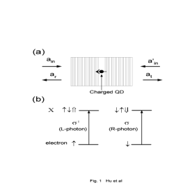
Singly charged QDs show the optical resonance of trion (also called negatively-charged exciton) which consists of two electrons bound to one hole warburton97 . Due to the Pauli exclusion principle, shows spin-dependent optical transitions [see Fig. 1(b)]hu98 : the left circularly polarized photon (indicated by L-photon) only couples the electron in the spin state to in the spin state with the two electron spins antiparallel; the right circularly polarized photon (indicated by R-photon) only couples the electron in the spin state to in the spin state . Here and represent electron spin states , and represent heavy-hole spin states . This spin selection rule for is also called Pauli blocking warburton97 ; calarco03 , and its imperfection due to the heavy-light hole mixing will be discussed later. For self-assembled QDs, the in-plane anisotropy lifts the degeneracy of the bright neutral exciton, which is called fine structure splitting, via the anisotropic electron-hole exchange interactions, but induces no splitting for the charged exciton due to the quenched exchange interaction bayer02 . Therefore, the spin levels of are degenerate as shown in Fig. 1(b). However, the in-plane anisotropy could modify the hole states and thus affect the spin selection rule. The light-hole sub-band and the split-off sub-band are energetically far apart from the heavy-hole sub-band and can be neglected. The spin is quantized along the normal direction of the cavity, i.e., the propagation direction of the input (or output) light.
For GaAs-based or InAs-based charged QDs, recent experiments have shown long electron spin coherence time (s) after suppressing the nuclear spin fluctuations petta05 , and long electron spin relaxation time (ms) kroutvar04 due to the suppressed electron-phonon and spin-orbit interactions in QDs. These results indicate that QD-confined spin is one of the promising solid-state quantum-bit (qubit) systems.
The reflection and transmission coefficients of this -cavity system can be investigated by solving the Heisenberg equations of motion for the cavity field operator and dipole operator , and the input-output relations walls94 :
| (2) |
where , , and are the frequencies of the input photon, cavity mode, and transition, respectively. g is the -cavity coupling strength and is the dipole decay rate. , are the cavity field decay rate into the input/output modes, and the leaky modes, respectively. The background absorption can also be included in . , are the noise operators related to reservoirs. , and , are the input and output field operators.
In the approximation of weak excitation where the charged QD is predominantly in the ground state, we take . The reflection and transmission coefficients in the steady state can be obtained
| (3) |
The weak excitation approximation demands that the intracavity photon number should be less than the critical photon number which measures the number of photons in the cavity required to saturate the QD response kimble94 . This condition is satisfied if the input beam is a train of single photons with the photon rate less than , where is the cavity lifetime. This situation is what we consider in this work exp1 . Moreover, for the high fidelity operation of the EBS, the spectral width of single photons should be much smaller than the linewidth of the cavity mode, i.e., the coherence length of single photons should be much longer than the cavity lifetime. This means the photon is never completely localized in the cavity, therefore, the charged QD almost remains in the ground state all the time. Although single photons as the input are discussed in this work and our previous work hu08 (as single photons are robust), we have to emphasize here that all discussions can be extended to a weak laser as the input as long as the weak excitation condition is satisfied. This can be done by replacing the single photon state with the coherent state. Details shall be discussed elsewhere hu09 .
Instead of the dispersive interaction raimond01 , we consider here the resonant interaction with . By taking , we get the reflection and transmission coefficients , for a uncoupled cavity (or cold cavity) where the QD does not couple to the cavity exp3 :
| (4) |
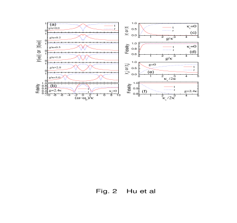
The reflection and transmission spectra versus the detuning are presented in Fig. 2(a) for different coupling strength g. With increasing g (e.g. by reducing the modal volume or increasing the oscillator strength), the cavity mode splits into two peaks due to the quantum interference in the “one-dimensional atom”regime waks06 with (which has been demonstrated recently englund07 ), and the vacuum Rabi splitting in the strong coupling regime reithmaier04 with . We can see that the transmittance or reflectance are different between the uncoupled cavity with and the coupled cavity (or hot cavity) with .
If the spin lies in the state , the L-photon feels a coupled cavity with reflectance and the transmittance , whereas the R-photon feels the uncoupled cavity with the reflectance and transmittance ; Conversely, if the spin lies in the state , the R-photon feels a coupled cavity, whereas the L-photon feels the uncoupled cavity. The difference in transmission and reflection, or even in the phase turchette95 ; hu08 , between the right and left circular polarizations are all called the giant circular birefringence induced by a single spin. This enables us to make a quantum device - an entanglement beam splitter. For any quantum input we can define the transmission operator as
| (5) |
and the reflection operator as
| (6) |
where , and , are the reflection and transmission coefficients of the uncoupled and coupled cavity, respectively. Both operators include the contributions from the uncoupled and coupled cavity.
In the strong coupling regime and in the central frequency regime , we have and [see Fig. 2(a)], thus the transmission operator can be simplified as
| (7) |
including the contribution from the uncoupled cavity only. Under the same conditions, we get . If the side leakage is small, i.e., , we have at [see Eq.(3)]. So the reflection operator can be simplified as
| (8) |
including the contribution from the coupled cavity only.
Thus we get the EBS transmission and reflection operators defined in Eq. (1): and where the coefficients determine the EBS efficiency. As and when , the EBS can be made efficient by optimizing the pillar cavity (e.g., suppress the side leakage and other loss reitzenstein07 ).
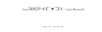
The EBS can directly split a photon-spin product state into two constituent entangled states via transmission and reflection (see Fig. 3). However, the entanglement fidelity is different between transmission and reflection. We can define the amplitude entanglement fidelity for the transmission and reflection operators as
| (9) |
As shown in Fig. 2(b) and Fig. 2(d), near-unity entanglement fidelity in transmission (solid curve) can be achieved within a small frequency window in the strong coupling regime . The strongly coupled QD-cavity has been demonstrated in various microcavities and nanocavities recently reithmaier04 , and can be achieved for the In(Ga)As QD-cavity system reithmaier04 ; reitzenstein07 ; exp2 . Experimentally is about several eV, so we take . Our calculations are based on these experimental values. High fidelity in reflection occurs in a much narrower bandwidth with unity achieved only at [see Fig. 2(b), dotted curve], and shows no dependence on g [see Fig. 2(d), dotted curve] due to when , suggesting we could make high-fidelity entanglement even in the weakly coupling regime. However, a practical pillar microcavity has side leakage which reduces the entanglement fidelity [see Fig. 2(f)]. shows a weak dependence on the side leakage (solid curve), but decreases rapidly (dotted curve) because when is significant.
The spin selection rule is not perfect for a realistic QD due to the heavy-light hole mixing. This can reduce the entanglement fidelity by a few percent as the hole mixing in the valence band is in the order of a few percent bester03 ; calarco03 [e.g., for self-assembled In(Ga)As QDs]. The hole mixing could be reduced by engineering the shape and size of QDs or choosing different types of QDs.
The exciton dephasing can also reduce the entanglement fidelity by amount of , where is the cavity photon lifetime and is the exciton coherence time. Two kinds of dephasing processes should be mentioned here: the optical dephasing and the spin dephasing of . It is well-known that the optical coherence time of excitons in self-assembled In(Ga)As QDs can be as long as several hundred picoseconds borri01 , which is ten times longer than the cavity photon lifetime (around tens of picoseconds in the strong coupling regime for cavity Q-factor of ). So the optical dephasing can only slightly reduce the entanglement fidelity by less than . The spin dephasing of the is mainly due to the hole-spin dephasing. In the absence of the contact hyperfine interaction that happens for holes heiss07 , the QD-hole spin is expected to have long coherence time, and ns has been reported recently brunner09 . This spin coherence time is at least three orders of magnitude longer than the cavity photon lifetime, so the spin dephasing of the can be safely neglected in our considerations.
The photon-spin entanglement enables us to make an ideal quantum measurement of the single spin by measuring the helicity of the transmitted or reflected photon. Although the resonant interaction is considered here, the weak excitation condition implies the real excitation of transition is negligible. As a result, the spin disturbance by the input photon is small. This optical spin-detection method, as well as another way based on the giant Faraday rotation hu08 , is thus a single-shot quantum non-demolition measurement (QND) grangier98 .
The QD-spin eigenstate can be prepared, for example, by optical spin pumping and cooling atature06 . The proposed single-shot QND measurement could also be used to prepare/cool the spin state via single-photon measurement liu05 , or via quantum Zeno effect misra77 . The spin superposition state can be made from the eigenstates by performing single spin rotations using nanosecond ESR pulses or picosecond optical pulses as reported recentlyberezovsky08 .

III Photon-spin quantum interface
We could use the created photon-spin entanglement as a resource to teleport the state from a photon to a spin bennett93 , thus making a quantum interface yao05 which is a crucial component for quantum networks cirac97 . However, we can do it directly using our EBS. In Fig. 4(a), a photon in an arbitrary state is sent to the cavity with the spin prepared in the state . After transmission, the photon and the spin become entangled, i.e,
| (10) |
By applying a Hadamard gate on the photon state using a polarizing beam splitter, we obtain a spin state on detecting a photon in the or state. Therefore, the photon state is transferred to the spin. The storage time is limited by the spin coherence time (s) petta05 .
In Fig. 4(b), a photon in the polarization state is sent to the cavity with the spin in an arbitrary state . After transmission, the state transforms to the same state as Eq. (10). After applying a Hadamard gate on the spin (e.g., using a microwave or optical pulse berezovsky08 ), the spin is detected in the and basis by the QND measurement as discussed above. Depending on the measured spin states, the photon is then projected in the state , and the spin state is transferred to the photon.
The state transfer can also be performed if the photon is reflected. Therefore, the total success probability is , which can reach if the cavity is optimized and . The state transfer fidelity is limited by the entanglement fidelity discussed in Sec. II.

IV Entangling independent photons
Another application of the EBS is to create polarization entanglement between independent photons (see Fig. 5). Photon 1 and photon 2 are both prepared in the superposition state and sent to the cavity in sequence. The spin is prepared in the state .
If both photons are transmitted [see Fig. 5(a)] with a possibility of , the state transformation is
| (11) |
After applying a Hadamard gate on the electron spin berezovsky08 , the spin is detected in the and basis by the QND measurement using another photon in H or V polarization. Depending on the measured spin states, we get two Bell states .
Similarly, if the two photons are both reflected [see Fig. 5(b)]with a possibility of , the Bell states can be obtained again. If one photon is transmitted and another reflected [see Fig. 5(c)] with a possibility of , we get another two Bell states . So the full set of Bell states can be created. This EBS-based entanglement scheme is efficient if the cavity is optimized and [see Fig.2(c) and (e)]. The time interval between two photons should be much shorter than the spin coherence time (s) to achieve high entanglement fidelity hu08 , but it should be long enough to make the weak excitation approximation valid exp1 . Note that this deterministic scheme for photon entanglement generation is immune to the fine structure splitting in realistic semiconductor QDs bayer02 as discussed in Sec. II, in contrast to another scheme based on the biexciton cascade emissions stevenson06 where the fine structure splitting should be suppressed to get high entanglement fidelity (this is a hard task).
This scheme can be extended to deterministically generate multi-photon entanglement devitt07 , such as Greenberger-Horne-Zeilinger(GHZ) states greenberger90 or cluster states briegel01 , by repeating the above Bell-state creation procedure to increase the size. An alternative way to create multi-qubit entanglement is entangling in different degrees of freedom with no need to increase the number of photons. This type of entanglement is called hyper-entanglementkwiat97 . If we take the spatial modes (different paths) in Fig. 5 into account, we actually create the two-photon three-qubit states entangled in polarization and spatial modes.
V Conclusions and outlook
We have proposed an entanglement beam splitter which can directly split a product state into two constituent entangled states with high fidelity and efficiency using a QD spin strongly coupled to an optical microcavity. This device is robust and is immune to the fine structure splitting in a realistic QD. This entanglement beam splitter can be used to deterministically create photon-spin, photon-photon, and spin-spin entanglement. This high-fidelity entanglement would find wide applications in quantum communications such as quantum cryptography and quantum teleportation gisin02 . Moreover, this entanglement is essential to implement a quantum busspiller06 , quantum interface yao05 , quantum memories and quantum repeaters briegel98 , all of which are critical building blocks for quantum networks cirac97 . The high-order multiparticle entanglement could be used for entanglement-enhanced quantum measurement giovannetti04 , or cluster-state based quantum computing raussendorf01 ; nielsen06 . The single-shot QND measurement could be used to prepare or cool the single spin state.
The entanglement beam splitter can also work as an active device such as a polarization-controlled single photon source driven by the electron spin dynamics. This source benefits from cavity quantum electrodynamics, therefore it has high high quantum efficiency cui05 and time-bandwidth limited photon pulses santori02 . On the other hand, techniques for manipulating single photons are well developed, and significant progress on fast QD-spin cooling and manipulating has been made recently atature06 ; berezovsky08 . Together with this work and our previous work hu08 , we believe that the QD spin-cavity systems are quite promising for solid-state quantum networks and scalable quantum computing.
It’s worthy to point out here that the entanglement beam splitter can be also made from a QD-hole spin in a double-sided microcavity because the positively charged exciton is governed by the same spin selection rule as the negatively charged exciton heiss07 ; brunner09 . Recent experiments have demonstrated that the QD-confined hole has long spin relaxation time ( ms) heiss07 and spin coherence time ( ns)brunner09 due to the suppressed electron-phonon interaction and the lack of hole-nuclear hyperfine interaction. Moreover, the cooling and fast coherent control of hole-spin states have been reported recently heiss07 ; ramsay08 ; brunner09 . Therefore, this type of entanglement beam splitter based on the hole spin is also promising.
ACKNOWLEDGMENTS
C.Y.H. thanks M.S. Kim, M. Atatüre, X.Q. Zhou, S. Bose, and S. Popescu for helpful discussions. J.L.O’B. and J.G.R. each acknowledge support from the Royal Society. This work is partly funded by EPSRC-GB IRC in Quantum Information Processing, QAP (Contract No. EU IST015848), and MEXT from Japan.
References
- (1) R. Loudon, The Quantum Theory of Light (Oxford Scientific Publications, Oxford, 2003).
- (2) N. Gisin, G. Ribordy, W. Tittel, and H. Zbinden, Rev. Mod. Phys. 74, 145 (2002).
- (3) E. Knill, R. Laflamme, and G. Milburn, Nature (London) 409, 46 (2001).
- (4) P. Kok, W. J. Munro, K. Nemoto, T. C. Ralph, J. P. Dowling, and G. J. Milburn, Rev. Mod. Phys. 79, 135 (2007); J. L. O’Brien, Science 318, 1567 (2007).
- (5) C. K. Hong, Z. Y. Ou and L. Mandel, Phys. Rev. Lett. 59, 2044 (1987).
- (6) V. Giovannetti, S. LIoyd, and L. Maccone, Science 306, 1330 (2004).
- (7) D. Fattal, K. Inoue, J. Vučković, C. Santori, G. S. Solomon, and Y. Yamamoto, Phys. Rev. Lett. 92, 037903 (2004); D. Fattal, E. Diamanti, K. Inoue, and Y. Yamamoto, Phys. Rev. Lett. 92, 037904 (2004).
- (8) R.Okamoto, J.L. O’Brien, H.F. Hofmann, T. Nagata, K. Sasaki, S. Takeuchi, Science 323, 483 (2009).
- (9) H.F. Hofmann and S. Takeuchi, Phys. Rev. Lett. 88, 147901 (2002).
- (10) C.Y. Hu, A. Young, J. L. O’Brien, W. J. Munro, and J. G. Rarity, Phys. Rev. B 78, 085307 (2008); C.Y. Hu, W.J. Munro, and J.G. Rarity, Phys. Rev. B 78, 125318 (2008).
- (11) R. J. Warburton, C. S. Dürr, K. Karrai, J. P. Kotthaus, G. Medeiros-Ribeiro, and P. M. Petroff, Phys. Rev. Lett. 79, 5282 (1997).
- (12) C.Y. Hu, W. Ossau, D.R. Yakovlev, G. Landwehr, T. Wojtowicz, G. Karczewski, and J. Kossut, Phys. Rev. B 58, R1766 (1998).
- (13) T. Calarco, A. Datta, P. Fedichev, E. Pazy, and P. Zoller, Phys. Rev. A 68, 012310 (2003).
- (14) M. Bayer, G. Ortner, O. Stern, A. Kuther, A. A. Gorbunov, A. Forchel, P. Hawrylak, S. Fafard, K. Hinzer, T. L. Reinecke, S. N. Walck, J.P. Reithmaier, F. Klopf, and F. Schäfer, Phys. Rev. B 65, 195315 (2002); J.J. Finley, D.J. Mowbray, M.S. Skolnick, A.D. Ashmore, C. Baker, A.F.G. Monte, and M. Hopkinson, Phys. Rev. B 66, 153316(2002).
- (15) J. R. Petta, A. C. Johnson, J. M. Taylor, E. A. Laird, A. Yacoby, M. D. Lukin, C. M. Marcus, M. P. Hanson, and A. C. Gossard, Science 309, 2180 (2005); A. Greilich, D. R. Yakovlev, A. Shabaev, Al. L. Efros, I.A. Yugova, R. Oulton, V. Stavarache, D. Reuter, A. Wieck, and M. Bayer, Science 313, 341 (2006); Xiaodong Xu, Wang Yao, Bo Sun, Duncan G. Steel, Allan S. Bracker, Daniel Gammon, and L.J. Sham, Nature, 459, 1105 (2009).
- (16) J. M. Elzerman, R. Hanson, L. H. Willems van Beveren, B. Witkamp, L. M. K. Vandersypen, and L. P. Kouwenhoven, Nature (London) 430, 431(2004); M. Kroutvar, Y. Ducommun, D. Heiss, M. Bichler, D. Schuh, G. Abstreiter, and J. J. Finley, Nature (London) 432, 81 (2004).
- (17) D.F. Walls and G.J. Milburn, Quantum Optics (Springer-Verlag, Berlin, 1994).
- (18) H.J. Kimble, Cavity Quantum Electrodynamics, Edited by P. Berman (Academic Press, San Diego, 1994).
- (19) By taking the parameters used in this paper, i.e, and , we get the critical photon number . If taking ps for a microcavity with and m, the single photon rate should be less than MHz to make the weak excitation approximation valid. If the mode-mismatch is included, the single photon rate can be slightly higher.
- (20) C.Y. Hu et al, (unpublished).
- (21) J. M. Raimond, M. Brune, and S. Haroche, Rev. Mod. Phys. 73, 565 (2001).
- (22) Experimentally we can measure the side leakage rate by measuring the ratio .
- (23) E. Waks and J. Vučković, Phys. Rev. Lett. 96, 153601 (2006); A. Auffeves-Garnier, C. Simon, J.M. Gerard, and J.P. Poizat, Phys. Rev. A 75, 053823 (2007).
- (24) D. Englund, D. Fattal, E. Waks, G. Solomon, B. Zhang, T. Nakaoka, Y. Arakawa, Y. Yamamoto, and J. Vuc̆ković, Nature(London) 450, 857 (2007).
- (25) J.P. Reithmaier, G. Sȩk, A. Löffler, C. Hofmann, S. Kuhn, S. Reitzenstein, L. V. Keldysh, V. D. Kulakovskii, T. L. Reinecke, A. Forchel, Nature 432, 197 (2004);T. Yoshie, A. Scherer, J. Hendrickson, G. Khitrova, H. M. Gibbs, G. Rupper, C. Ell, O. B. Shchekin,D.G. Deppe, Nature 432, 200 (2004); E. Peter, P. Senellart, D. Martrou, A. Lemaître, J. Hours, J. M. Gérard, and J. Bloch, Phys. Rev. Lett. 95, 067401 (2005).
- (26) Q. A. Turchette, C. J. Hood, W. Lange, H. Mabuchi, and H. J. Kimble, Phys. Rev. Lett. 75, 4710 (1995).
- (27) S. Reitzenstein, C. Hofmann, A. Gorbunov, M. Strauß, S. H. Kwon, C. Schneider, A. Löffler, S. Höfling, M. Kamp, and A. Forchel, Appl. Phys. Lett. 90, 251109 (2007).
- (28) g and can be controlled independently as g is determined by the oscillator strength and the cavity modal volume, while by the cavity quality factor only.
- (29) G. Bester, S. Nair, and A. Zunger, Phys. Rev. B 67, 161306(R) (2003).
- (30) P. Borri, W. Langbein, S. Schneider, U. Woggon, R. L. Sellin, D. Ouyang, and D. Bimberg, Phys. Rev. Lett. 87, 157401 (2001); D. Birkedal, K. Leosson, and J. M. Hvam, Phys. Rev. Lett. 87, 227401 (2001); W. Langbein, P. Borri,U. Woggon, V. Stavarache, D. Reuter, and A. D. Wieck, Phys. Rev. B 70, 033301 (2004).
- (31) D. Heiss, S. Schaeck, H. Huebl, M. Bichler, G. Abstreiter, J.J. Finley, D. V. Bulaev, and D. Loss, Phys. Rev. B 76, 241306(R) (2007); B.D. Gerardot, D. Brunner, P.A. Dalgarno, P. öhberg, S. Seidl, M. Kroner, K. Karrai, N.G. Stoltz, P.M. Petroff, and R.J. Warburton, Nature(London) 451, 441 (2008).
- (32) D. Brunner, B.D. Gerardot, P.A. Dalgarno, G. Wüst, K. Karrai, N.G. Stoltz, P.M. Petroff, and R.J. Warburton, Science 325, 70 (2009).
- (33) P. Grangier, J.A. Levenson, and J.P. Poizat, Nature(London) 396, 537 (1998).
- (34) M. Atatüre, J. Dreiser, A. Badolato, A. Hogele, K. Karrai, and A. Imamoglu, Science 312, 551 (2006); Xiaodong Xu, Yanwen Wu, Bo Sun, Qiong Huang, Jun Cheng, D. G. Steel, A. S. Bracker, D. Gammon, C. Emary, and L.J. Sham, Phys. Rev. Lett. 99, 097401 (2007).
- (35) R.B. Liu, W. Yao, and L.J. Sham, Phys. Rev. B 72, 081306(R) (2005).
- (36) B. Misra and E.C.G. Sudarshan, J. Math. Phys. 18, 756 (1977); W.M. Itano, D.J. Heinzen, J. J. Bollinger, and D.J. Wineland, Phys. Rev. A 41, 2295 (1990).
- (37) J. Berezovsky, M.H. Mikkelsen, N.G. Stoltz, L.A. Coldren, and D.D. Awschalom, Science 320, 349 (2008); D. Press, T.D. Ladd, B. Zhang, and Y. Yamamoto, Nature (London) 456, 218 (2008).
- (38) C.H. Bennett, G. Brassard, C. Crépeau, R. Jozsa, A. Peres, and W.K. Wootters, Phys. Rev. Lett. 70, 1895 (1993).
- (39) W. Yao, R.B. Liu, and L. J. Sham, Phys. Rev. Lett. 95, 030504 (2005).
- (40) J.I. Cirac, P. Zoller, H.J. Kimble, and H. Mabuchi, Phys. Rev. Lett. 78, 3221 (1997); H.J.Kimble, Nature (London) 453, 1023 (2008).
- (41) R. M. Stevenson, R. J. Young, P. Atkinson, K. Cooper, D. A. Ritchie, and A. J. Shields, Nature (London) 439, 179 (2006); N. Akopian, N. H. Lindner, E. Poem, Y. Berlatzky, J. Avron, D. Gershoni, B.D. Gerardot, and P. M. Petroff, Phys. Rev. Lett. 96, 130501 (2006).
- (42) Simon J. Devitt, Andrew D. Greentree, Radu Ionicioiu, Jeremy L. O’Brien, William J. Munro, and Lloyd C. L. Hollenberg, Phys. Rev. A 76, 052312 (2007); Ashley M. Stephens, Zachary W. E. Evans, Simon J. Devitt, Andrew D. Greentree, Austin G. Fowler, William J. Munro, Jeremy L. O’Brien, Kae Nemoto, and Lloyd C. L. Hollenberg, Phys. Rev. A 78, 032318 (2008).
- (43) M. Greenberger, M.A. Horne, A. Shimony, and A. Zeilinger, Am. J. Phys. 58, 1131 (1990).
- (44) H.J. Briegel and R. Raussendorf, Phys. Rev. Lett. 86, 910 (2001).
- (45) Paul G. Kwiat, J. Mod. Opt. 44, 2173 (1997).
- (46) T.P. Spiller, K. Nemoto, S.L Braunstein, W.J. Munro, P. van Loock, and G.J. Milburn, New J. Phys. 8, 30 (2006).
- (47) H.-J. Briegel, W. Dür, J. I. Cirac, and P. Zoller, Phys. Rev. Lett. 81, 5932 (1998); L.-M. Duan, M. D. Lukin, J. I. Cirac and P. Zoller, Nature (London) 414, 413(2001).
- (48) R. Raussendorf and H.J. Briegel, Phys. Rev. Lett. 86, 5188 (2001).
- (49) M.A. Nielsen, Rev. Math. Phys. 57, 147 (2006).
- (50) G.Q. Cui and M.G. Raymer, Opt. Express 13, 9660 (2005).
- (51) C. Santori, D. Fattal, J. Vuckovic, G.S. Solomon, and Y. Yamamoto, Nature (London) 419, 594 (2002).
- (52) A.J. Ramsay, S.J. Boyle, R.S. Kolodka, J.B.B. Oliveira, J. Skiba-Szymanska, H. Y. Liu, M. Hopkinson, A. M. Fox, and M. S. Skolnick, Phys. Rev. Lett. 100, 197401 (2008).