[1]\mbox
Casimir experiments showing saturation effects
Abstract
We address several different Casimir experiments where theory and experiment disagree. First out is the classical Casimir force measurement between two metal half spaces; here both in the form of the torsion pendulum experiment by Lamoreaux and in the form of the Casimir pressure measurement between a gold sphere and a gold plate as performed by Decca et al.; theory predicts a large negative thermal correction, absent in the high precision experiments. The third experiment is the measurement of the Casimir force between a metal plate and a laser irradiated semiconductor membrane as performed by Chen et al.; the change in force with laser intensity is larger than predicted by theory. The fourth experiment is the measurement of the Casimir force between an atom and a wall in the form of the measurement by Obrecht et al. of the change in oscillation frequency of a Bose-Einstein condensate trapped to a fused silica wall; the change is smaller than predicted by theory. We show that saturation effects can explain the discrepancies between theory and experiment observed in all these cases.
pacs:
42.50.Nn, 12.20.-m, 34.35.+a, 42.50.CtI Introduction
The Casimir force in the purest geometry is extremely fascinating: There is an attractive force between two parallel, perfectly reflecting metal plates embedded in vacuum; this geometry was treated by Casimir in his classical paper Casi of 1948. One may say that the fact that Maxwell’s equations have solutions in vacuum, that electromagnetic waves need no medium to propagate in, gives rise to these forces. One way to calculate the forces is to calculate the energy in the system and then take minus the derivative with respect to separation, , between the plates. At zero temperature the energy may be obtained as a summation of the zero-point energy of all the electromagnetic normal modes of the system. The normal modes change when changes and so do the zero-point energies. At finite temperature the actual population of the modes affects the forces.
If the idealized perfectly reflecting metallic plates are replaced by plates of real materials the boundary conditions are different. There is still a force, but it is now different. For real metals the vacuum modes penetrate to some extent into the plates and furthermore new modes appear, modes that are bound to the surfaces of the plates; these are evanescent waves, so-called surface modes Ser . For large separations the vacuum modes, or propagating waves, dominate and the force, at least at zero temperature, is identical to the force in the idealized system. For smaller separations the surface modes dominate and the force acquires different characteristics; in this range the force is called the van der Waals force.
In a pioneering work Sparnaay Spar tried to verify the existence of the Casimir force experimentally between two parallel plates. However, the uncertainties were of the same order of magnitude as the force itself so the experiment was non-conclusive. The interest in the Casimir force virtually exploded a decade ago. This increase in interest was spurred by the torsion pendulum experiment by Lamoreaux Lamo , which produced results with good enough accuracy for the comparison between theory and experiment to be feasible. This stimulated both theorists BosSer ; LamRey ; Bordag ; BreAar ; Svet ; Nogu and experimentalists Mohi ; Ede ; DecLop ; Bres and the field has grown constantly since then. Another reason for this increase of interest in Casimir forces is the huge shift of general focus of the science community into nanoscience and nanotechnology where these forces become very important.
A setback came immediately. Theory and experiment agree quite well for low temperatures, but at room temperature, where most experiments are performed there are serious deviations. Each new type of experiment has lead to new puzzling discrepancies between theory and experiment. In the torsion pendulum experiment by Lamoreaux Lamo and in the micromachined torsion oscillator experiment by Decca et al. Decca the Casimir force and Casimir pressure, respectively, were found to agree much better with the theoretical zero temperature results than with the room temperature results although both experiments were performed at room temperature. The problems appeared when one improved the treatment of the dielectric properties of the metals by inclusion of dissipation BosSer ; this can be done either by using tabulated, experimental optical data or by using the Drude dielectric function. The origin of the dissipation is carrier scattering against impurities and lattice imperfections; at finite temperature also carrier-phonon scattering contributes. Removing dissipation from the Drude dielectric function, i.e., using the so-called Plasma model has the effect that the discrepancies go away. One was facing the dilemma that improving the theory led to worse results. There were also claims that the theory did not obey the Nernst heat theorem, the second law of thermodynamics. This could, however, be shown not to be the case SerBos ; BosSer2 ; Brev . There still remained a problem for perfect crystals where the dissipation comes from phonon scattering, only. This was, however resolved by inclusion of spatial dispersion Ser2 ; it turned out that spatial dispersion had a very small effect on the Casimir force, but it removed the remaining problem with the Nernst heat theorem for perfect crystals.
The sphere and plate geometry used in these two experiments has the benefit compared to the two plate geometry used in Refs. Spar ; Bres that one avoids the alignment problem. However, one has to rely on the so-called proximity force approximation (PFA) Derj in the interpretation of the experiments and that could be a source of error. Fortunately, the PFA, although based on a rather shaky foundation, seems to work quite well SerRom .
To get a better insight into what goes wrong, or where, it would be very useful to have experiments performed in the whole temperature range from very low temperature up to room temperature or even higher, keeping everything else fixed. This is very difficult to do in practice. Chen et al. Chen came up with a very clever idea about how to collect complementing information. By using a gold sphere and a laser irradiated semiconductor wafer one could study how the force changed with carrier density in the wafer, keeping everything else fixed.
Here one was facing another setback. The change in force in the presence of light compared to in the absence of light was larger than expected. In the previous experiments one could get agreement between experiment and theory by neglecting the dissipation. In this experiment it did not matter if dissipation was included or not. One could get good agreement if one completely neglected the very few carriers, present in the absence of light but kept the contribution from the laser excited carriers in the presence of light. Thus, it seemed to be quite different reasons for the discrepancies in the two types of experiment.
Another experiment Ante where the Casimir force can be measured is based on Bose-Einstein condensates (BEC) near a surface. For a harmonically trapped BEC placed at a distance from the surface of a substrate the centre-of-mass oscillation frequency changes due to the surface-atom potential. Experiments were performed Obrecht on a BEC trapped to a fused silica wall. Theory predicted a too big a change in frequency. Good agreement was obtained if one neglected the contribution to the dielectric properties of the fused silica from the very small amount of thermally excited carriers in the material KliMos .
Thus, in the last two experimental setups it seems as if the dielectric properties of the carriers in a semiconducting system with very small carrier concentration have to be modified. This has been done in two recent publications Pita ; DalLam but if this resolves the problems is not so clear.
In this work we put forward what we think is the solution to all the problems discussed above, or at least the first step towards a solution. It is applicable to all the discussed experimental setups. The idea is that the discrepancies are due to saturation effects. We have previously discussed these ideas in a very short and condensed article Ser4 . Here, we make a much more detailed presentation. In Sec. II we present the formalism that is common to all three experimental geometries. Then all three geometries are treated one by one, starting by two metal plates in Sec. III, followed by the semiconductor and metal plates in Sec. IV, and ending by the atom wall geometry in Sec. V. Finally, we end with summary and discussions in Sec. VI.
II Basic Formalism
The formalism we use is based on the electromagnetic normal modes of the system Ser . At zero temperature the force, , between two objects as a function of separation, , is given by the derivative of the energy, :
| (1) |
where the energy is the sum of the zero-point energies of the modes,
| (2) |
In a simple system with a small number of well-defined modes this summation can be performed directly. In the general case this is not so. Then we can rely on an extension of the so-called Argument Principle Ser ; BrevEl to find the results. Let us study a region in the complex frequency plane. We have two functions defined in this region; one, , is analytic in the whole region; one, , has poles and zeros inside the region. The following relation holds for an integration path around the region:
| (3) |
where and are the zeros and poles, respectively, of function . In the Argument Principle the function is replaced by unity and the right hand side then equals the number of zeros minus the number of poles of the function inside the integration path. If we choose the function to be the function in the defining equation for the normal modes of the system, , the function as , and let the contour enclose all the zeros and poles of the function then Eq. (3) produces the energy in Eq. (2). By using this theorem we end up with integrating along a closed contour in the complex frequency plane. In most cases it is fruitful to choose the contour shown in Fig. 1.
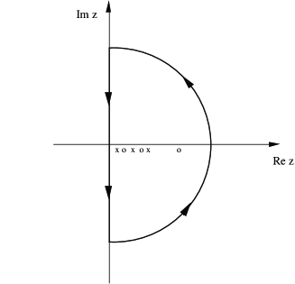
We have the freedom to multiply the function with an arbitrary constant without changing the result on the right hand side of Eq. (3). If we choose the constant carefully we can make the contribution from the curved part of the contour vanish and we are only left with an integration along the imaginary frequency axis:
| (4) |
where the result was obtained from an integration by parts. At finite temperatures the force is Ser5
| (5) |
where Helmholtz’ free energy is
| (6) |
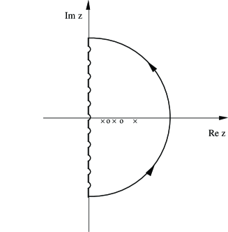
We make the observation that we may use the generalized Argument Principle but now with instead of for in the integrand. There is however one complication. This new function has poles of its own in the complex frequency plane. We have to choose our contour so that it includes all poles and zeros of the function but excludes the poles of . The poles of function all are on the imaginary frequency axis. We use the same contour as in Fig. 1, but now let the straight part of the contour lie just to the right of, and infinitesimally close to, the imaginary axis. We have
| (7) |
The coth function has poles on the imaginary z-axis and they should not be inside the contour. The poles are at
| (8) |
and all residues are the same, equal to . We integrate along the imaginary axis and deform the path along small semicircles around each pole. The integration path is illustrated in Fig. 2. The integration along the axis results in zero since the integrand is odd with respect to . The only surviving contributions are the ones from the small semicircles. The result is
| (9) |
Since the summand is even in we can write this as
| (10) |
where the prime on the summation sign indicates that the term should be multiplied by a factor of one half. This factor of one half is because there is only one term with in the original summation but two for all other integers. When the temperature goes to zero the spacing between the discrete frequencies goes to zero and the summation may be replaced by an integration:
| (11) |
and we regain the contribution to the internal energy from the interactions, the change in zero-point energy of the modes.
In all the three geometries we discuss in this work the interaction energy per unit area, , can at zero temperature be written on the form Ser
| (12) |
where is the distance between the objects, k the two-dimensional wave vector in the plane of the plate(s), the area of a plate, and is the condition for an electromagnetic normal mode in the particular geometry. The integration is along the imaginary frequency axis. At finite temperature the integration is replaced by a discrete summation over Matsubara frequencies,
| (13) |
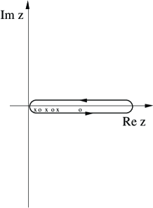
Alternatively one may integrate along the real frequency axis,
| (14) |
where is the distribution function for massless bosons. This form can also be used at zero temperature; then the distribution function vanishes. These last results one arrives at by using the contour in the complex frequency plane shown in Fig. 3.
The force per unit area, or pressure, is obtained as minus the derivative with respect to distance, .
In all three geometries there are two groups of normal mode, transverse magnetic (TM) and transverse electric (TE), each with a different mode condition function. The interaction potential is a sum of two terms, . In the two plate geometries the mode condition functions are
| (15) |
where the Fresnel amplitude reflection coefficients at an interface between medium i and j are
| (16) |
for TM modes (p-polarized waves) and
| (17) |
for TE modes (s-polarized waves), respectively. We have let the objects be of medium 1 and 2 and let the surrounding vacuum be denoted by medium 0. The gamma functions are
| (18) |
Now we have all material we need for now. The interaction potential for the atom wall geometry can also be derived from these relations using a limit procedure. We make that derivation in Sec. V.
III Two parallel metal plates
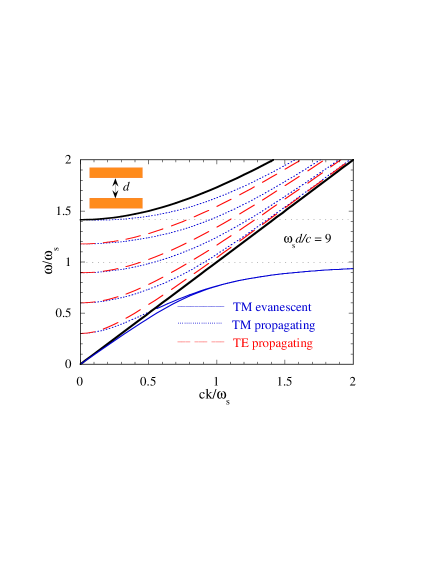
The dispersion curves for the electromagnetic normal modes for two gold plates Ser2 is shown in Fig. 4 . This figure is valid in neglect of dissipation in the plate materials. The modes are propagating (evanescent) above and to the left (below and to the right) of the light dispersion curve. The light dispersion curve is the straight diagonal line in the figure; it has slope unity with the chosen scaling of the axes. Note that there are no TE evanescent modes. When the system is allowed to have dissipation there are modes everywhere. Each original mode is replaced by a continuum of modes Ser3 . Evanescent TE modes appear and the continuum extends all the way down to the momentum axis. These modes are the cause of all the problems with the thermal Casimir force in this geometry.
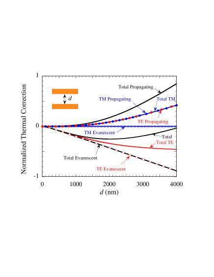
In Fig. 5 we show the thermal correction to the Casimir energy. The contribution from all four mode types are given separately. These curves have been obtained from Eq. (14) and the Drude dielectric function suited for gold has been used. We note that the TE evanescent waves give a negative contribution. For larger separations the total TE contribution saturates when it has completely eliminated the zero temperature TE contribution.
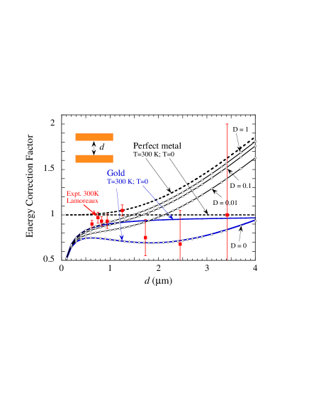
In Fig. 6 we show the energy correction factor for the two-gold-plate geometry. The energy correction factor is the Casimir energy per unit area divided by the zero temperature Casimir energy per unit area for two perfectly reflecting metal plates, . The experimental results Lamo obtained by Lamoreaux are shown as squares with error bars. The larger the separation the bigger the errors. There is a cluster of experimental points near separation. Here the deviation between theory and experiment is over . Theory and experiment are in clear disagreement. The proposed prescription has been to neglect the dissipation in the intraband part of the dielectric function but keep it in the interband part MosGey .
Let us now explain our view of what goes wrong in the theory of the thermal Casimir effect in presence of dissipation. The traditional theory relies fully on the concept of electromagnetic normal modes. These are assumed to be independent massless bosons. The possibility to excite one of these modes is assumed to be completely independent of how many modes are already excited. An excitation of a mode involves excitations of the charged particles in the system, electrons in the geometries studied here. These are the sources of the fields. Now, the electrons are fermions and there is at most one electron in each particle state. An electron that is excited at one instant of time cannot immediately be excited again – the state is empty. The more modes that are excited the more difficult it is to excite new modes — there are saturation effects. It is a matter of logistics. In the theoretical treatment this is not taken care of. In most cases this fact will not cause any problems, but sometimes it could. We think that the thermal Casimir effect is one such case. When dissipation is included each mode is replaced by a continuum of an infinite number (for an infinite system) of new modes. The distribution function diverges towards zero frequency and the saturation effects should appear here. This is very difficult to treat in a strict way. We use an approximation which is very easy to implement. We shift the distribution function in Eq. (14) downwards in frequency, so that it never reaches the point of divergence, by adding a damping parameter, ,
| (19) |
The discrete frequency summation in Eq. (13) is the result of the poles of the distribution function that all fall on the imaginary axis, see Ref. Ser . Our new distribution function has its poles shifted away from the axis the distance into the left half plane. The new form of the interaction potential is
| (20) |
Each term in the summation is replaced by an integral. For small values it is enough to replace only the zero frequency term.
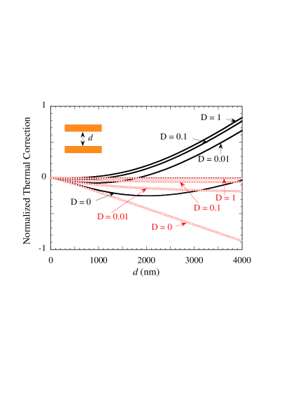
The circles in Fig. (6) are the results with damping parameters 0, 0.01, 0.1, and 1.0, respectively, counting from below. We have used Eq. (14) with the modified distribution function to get the thermal correction. A word of caution is in place. This approach changes the population of modes at all energies, not just at the low frequency limit where saturation effects are predicted to appear. To limit the damage of this we have just taken into account the change in the contribution from TE evanescent waves. These contributions are the dominating ones at low energies. In Fig. 7 we show the thermal correction from the TE evanescent waves, including the damping, as circles and the total correction as solid curves.
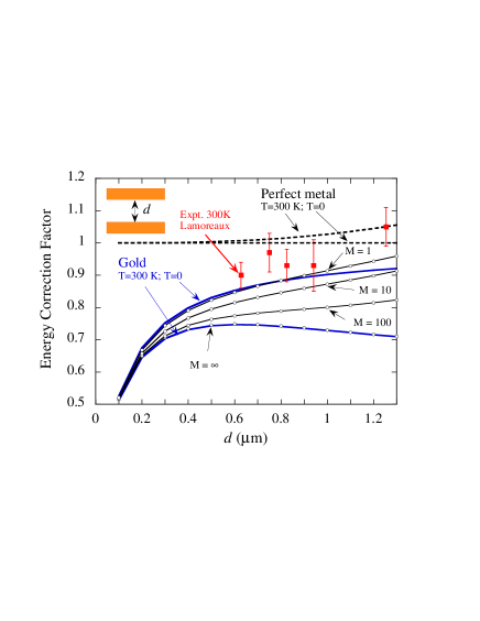
An alternative way to treat the saturation is to simply introduce a cutoff in the distribution function. In Fig. 8 we show the results for the energy correction factor from using Eq. (14) with a cutoff. The parameter M is the maximum allowed value of the distribution function. We have here limited the separation range to focus on the interesting cluster of experimental points near separation. This cutoff method forces us to stay on the real frequency axis where the results are more sensitive to variations in the dielectric function and the numerical calculation more difficult to perform.
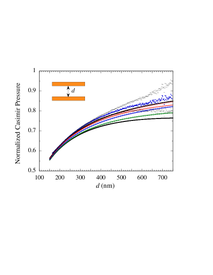
The experimental result Decca for the normalized Casi-mir pressure at 295 K is shown as dots in Fig. 9. The bars are the endpoints of the experimental error bars. The upper (lower) thick solid curve is the theoretical result for zero temperature (295 K) calculated with Eqs. (12) and (13), respectively. The dielectric function on the imaginary frequency axis was derived from experimental tabulated optical data for gold. We note that the zero temperature result agrees much better with the experimental result. The large negative thermal correction comes entirely from the TE evanescent modes TorLam . All curves are normalized with the zero temperature Casimir pressure between two perfectly reflecting metal plates, . We have neglected surface roughness effects. The circles are the results for different damping parameters from using Eq. (14) with the modified distribution function of Eq. (19) in the contribution from the TE evanescent waves. To each set of circles corresponds a thin solid curve. This curve is the result of using Eq. (13), where just the zero frequency pole of the cosh function has been moved into the left half of the complex frequency plane and the corresponding term in the summation has been modified according to Eq. (20). We note that for the two lowest set of curves with small damping the two results agree. For very high damping there are deviations. These deviations have two reasons: One is that in the thin solid curves all mode types are affected by the damping; the second is that for strong enough damping more terms in the summation, leading to the sets of circles, should be modified.
IV Two parallel plates, one metallic and one semiconducting
The third experiment we consider here is the measurement of the Casimir force between a gold plate and a laser irradiated semiconductor membrane as performed by Chen et al. Chen . They measured the change in force with the laser irradiation compared to without any irradiation. The idea is to find out how the force varies with carrier concentration in the semiconducting membrane. The results are shown in Fig. 10. The open squares with error bars are the experimental result. The dashed curve with open circles is the theoretical result for 300 K. The deviations are clear. In this geometry it is not enough to neglect dissipation to get agreement with experiment; the theoretical results with and without dissipation are very similar. Besides, it is now the TM modes that cause the problems. In the non-irradiated semiconductor material there is always some thermally excited carriers present. One postulated that for the non-irradiated semiconductor one should completely omit the contribution to the dielectric function from the thermally excited carriers. That brought theory and experiment into agreement, see Fig. 10 in Ref. Chen . In the present Fig. 10 the solid curve with filled (open) circles is our saturation based result with equal to 0.01 (0.1). We find that both these curves agree with the experiment within the experimental uncertainty. Here we have used Eq. (13) and just modified the zero frequency contribution according to Eq. (20). We have derived the dielectric function for the gold plate from experimental tabulated optical data. For the silicon with and without laser irradiation we have used the dielectric function given in Ref. Chen .
V Atom wall geometry
The Casimir force between an atom and a wall can be obtained from the results of the two plate geometry. One takes the limit when the thickness of one of the plates goes to zero and at the same time lets the material of the thin plate be diluted. We start with a half space of medium 1 and a layer of medium 2 emersed in vacuum (medium 0) separated by the distance . The function in the condition for electromagnetic normal modes is then given by
| (21) |
where we have suppressed the arguments and . We have furthermore divided the original function with the one corresponding to infinite separation. This corresponds to choosing our reference system to be the one at infinite separation. There will be one function like this for TM modes and one for TE modes. Using that the thickness of layer 2 is small and that the material in this layer is diluted with a small reflection coefficient as a result leads to
| (22) |
We now let the dielectric function in the layer be . We have assumed that there is only one atom in the layer, with polarizability . At this point we need to specify the mode type. We start with TE modes:
| (23) |
We furthermore have
| (24) |
Thus, the result is
| (25) |
For the TM modes we have
| (26) |
and in the limit
| (27) |
In this geometry we want the interaction energy, not the interaction energy per unit area, so we multiply with the area of the plate and find
| (28) |
for zero temperature and
| (29) |
for finite temperature, where
| (30) |
and
| (31) |
respectively. We note that the zero frequency contribution vanishes for the TE modes, but not for the TM modes. The force between the atom and the wall is
| (32) |
where the first term is the TE contribution and the second the TM contribution. The suppressed arguments of the functions in the integrand are .
In the experiment by Obrecht et al. Obrecht one studied indirectly the force between a rubidium atom and a dielectric substrate. This was done by measuring the collective oscillation frequency of the mechanical dipole mode of a BEC near enough to a dielectric substrate for the force to measurably distort the trapping potential. In that work one studied both the equilibrium case when the substrate was of the same temperature as the surrounding environment and the non-equilibrium case when the substrate was of a different temperature. We concentrate on the equilibrium case when both the surroundings and the wall have the same temperature, 310 K. The fractional change in trap frequency is defined as in terms of the unperturbed trap frequency, , and , the trap frequency perturbed by the force. This may be obtained as
| (33) |
where the expression for is identical to Eq. (32) except that the integrand or summand has an extra factor . In the experiment is the amplitude of oscillation, is the Thomas-Fermi radius in the -direction and is the mass of the rubidium atom. The function is the Bessel function and . These results were obtained in Ref. KliMos after an analytical averaging procedure had been performed.
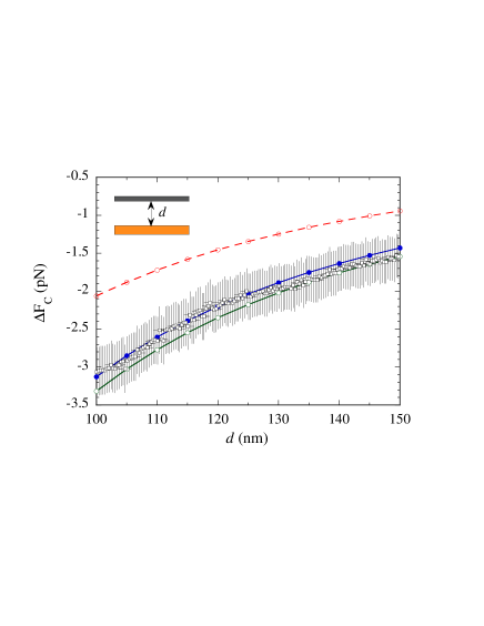
In Fig. 11 the experimental result Obrecht is shown as open squares with error bars. The upper (lower) curve is the theoretical result, without saturation, including (neglecting) the conductivity from the few thermal carriers in the silica wall. We see that also here the neglect of the contribution, to the dielectric function of the silica wall, from the very few thermally excited carriers brings the theoretical result into agreement with experiment. This neglect is the postulated remedy in Ref. KliMos . In this geometry, just as in gold-plate silicon-wafer geometry, the TM modes cause the problems and it is not enough to neglect dissipation to get good agreement between theory and experiment. To include saturation effects we have just modified the zero frequency contribution in analogy with Eq. (20). We note that in this experiment it is enough to have a damping parameter as small as to bring the theoretical result into agreement with experiment. We have assumed that the thermally excited carriers in the wall material have the conductivity (), which is the upper limit of the range given in Ref. KliMos . Using smaller values leads to even weaker demands on the damping parameter.
VI summary and discussions
In summary we have proposed that saturation effects are responsible for the discrepancy between theory and experiment in several quite different Casimir geometries. It is quite difficult or even impossible to derive the saturation effects from first principles. We have treated saturation within a very simple calculation model and demonstrated that the problems may go away in all cases. The basic assumption is that the electromagnetic normal modes can not be fully treated as independent massless bosons. There are limitations on the number of excited modes and this limitation shows up at low frequencies where the distribution function for massless bosons diverges in the case of non-zero temperature. We encourage experimentalists to design experiments where the occupation of these modes is directly investigated.
Acknowledgements.
We are grateful to R.S. Decca, G.L. Klimchitskaya, and U. Mohideen for providing us with experimental data. The research was sponsored by the VR-contract No:70529001 and support from the VR Linné Centre LiLi-NFM and from CTS is gratefully acknowledged.References
- (1) H. B. G. Casimir, Proc. K. Ned. Akad. Wet. 51, 793 (1948).
- (2) Bo E. Sernelius,Surface Modes in Physics (Wiley-VCH, Berlin, 2001).
- (3) M. J. Sparnaay, Physica 24, 751 (1958)
- (4) S. K. Lamoreaux, Phys. Rev. Lett. 78, 5 (1997).
- (5) M. Boström and Bo E. Sernelius, Phys. Rev. Lett 84, 4757 (2000).
- (6) A. Lambrecht, and S. Reynaud, Eur. Phys. J. D 8, 309 (2000).
- (7) M. Bordag, B. Geyer, G. L. Klimchitskaya, and V. M. Mostepanenko, Phys. Rev. Lett 87, 259102 (2001).
- (8) I. Brevik, J. B. Aarseth, and J. S. Høye, Phys. Rev. E 66, 026119 (2002).
- (9) V. B. Svetovoy, and M. V. Lokhanin, Mod. Phys. Lett. A 15, 1437 2000
- (10) C. Noguez, C. E. Román-Velázquez, R. Esquivel-Sirvent, and C. Villarreal, Europhys. Lett. 67, 191 (2004).
- (11) U. Mohideen, and A. Roy, Phys. Rev. Lett. 81, 4549 (1998).
- (12) T. Ederth, Phys. Rev. A 62, 062104 (2000).
- (13) R. S. Decca, D. López, E. Fischbach, and D. E. Krause, Phys. Rev. Lett. 91, 050402 (2003).
- (14) G. Bressi, G. Carugno, R. Onofrio, and G Ruoso, Phys. Rev. Lett. 88, 041804 (2002).
- (15) R. S. Decca, D. Lopéz, E. Fischbach, G. L. Klimchitskaya, D. E. Krause, and V. M. Mostepanenko, Phys. Rev. D 75, 077101 (2007).
- (16) Bo E. Sernelius, and M. Boström, in Quantum Field Theory Under the Influence of External Conditions, Ed. K.A. Milton (Rinton Press, Princeton 2004).
- (17) M. Boström, and Bo E. Sernelius, Physica A 339, 53 (2004).
- (18) I. Brevik, J.B. Aarseth, J. S. Høye and K.A. Milton, in Quantum Field Theory Under the Influence of External Conditions, Ed. K.A. Milton (Rinton Press, Princeton 2004).
- (19) Bo E. Sernelius, Phys. Rev. B 71, 235114 (2005).
- (20) B. Derjaguin, Kolloid-Z. 69, 155 (1934).
- (21) Bo E. Sernelius, and C. E. Román-Velázquez, Phys. Rev. A 78, 032111 (2008).
- (22) F. Chen, G. L. Klimchitskaya, V. M. Mostepanenko, and U. Mohideen, Phys. Rev. B 76, 035338 (2007).
- (23) M. Antezza, J. Phys. A:Math. Gen. 39, 6117 (2006).
- (24) J. M. Obrecht, R. J. Wild, M. Antezza, L. P. Pitaevskii, S. Stringari, and E. A. Cornell, Phys. Rev. Lett. 98, 063201 (2007).
- (25) G. L. Klimchitskaya and V. M. Mostepanenko, J. Phys. A:Math. Theor. 41, 312002 (2008).
- (26) L. P. Pitaevskii, Phys. Rev. Lett. 101, 163202 (2008).
- (27) D. A. R. Dalvit and S. K. Lamoreaux, Phys. Rev. Lett. 101, 163203 (2008).
- (28) Bo E. Sernelius, EPL 87 (2009) 14004.
- (29) I. Brevik and E. Elizalde, Physical Review D 49, 5319 (1994); M. Bordag, E. Elizalde and K. Kirsten, Journal of Mathematical Physics 37, 895-916 (1996); M. Bordag, E. Elizalde, K. Kirsten and S. Leseduarte, Physical Review D 56, 4896-4904 (1997).
- (30) Bo E. Sernelius, Phys. Chem. Chem. Phys. 6, 1363 (2004).
- (31) Bo E. Sernelius, Phys. Rev. B 74, 233103 (2006).
- (32) M. Boström, Van der Waals and Casimir interactions near metal films, PhD thesis at Linköping University (2000).
- (33) V. M. Mostepanenko and B. Geyer, J. Phys. A:Math. Theor. 41, 164014 (2008).
- (34) J. R. Torgerson, and S. K. Lamoreaux, Phys. Rev. E 70, 047102 (2004).