Plasmonic electromagnetically-induced transparency in symmetric structures
Abstract
A broken symmetry is generally believed to be a prerequisite of plasmonic electromagnetically-induced transparency (EIT), since the asymmetry renders the excitation of the otherwise forbidden dark mode possible. Nevertheless, according to the picture of magnetic-plasmon resonance (MPR) mediated plasmonic EIT, we show that the plasmonic EIT can be achieved even in the symmetric structures based on the second-order MPR. This sharpens our understanding of the existing concept, but also a profound insight into the plasmonic coherent interference in the near-field zone.
pacs:
78.20.Ci, 42.25.Bs, 78.67.PtElectromagnetically-induced transparency (EIT) is an important quantum interference effect induced by the interaction between the laser beams and atom ensembles under two-photon resonance condition.Boller1991PRL ; Harris1997phystoday ; Fleischhauer2005PMP This effect can be applied to quantum communication,LukinPRL2000 slow-light, and enhanced nonlinear effects.HarrisPRL1999 Compared to the EIT of atomic system, the plasmonic EIT in metamaterials has the advantages, such as manipulation at room temperature, excitation of single optical field, integration of nanoplasmonic circuits. Therefore, a great deal of attention has been paid to the classical analogue of EIT in mechanical oscillators, RLC circuits,AlzarAJP2002 optical resonators,OpatrnyPRA2001 optical dipole antennas,Zhang2008PRL ; Xu2009 ; Lu2009 ; LiuNM2009 trapped-mode patterns,PapasimakisPRL2008 split-ring resonators,TassinPRL2009 ; SinghPRB2009 and array of metallic nanoparticles.YannopapasPRB2009
Thanks to this a merging of plasmonics and metamaterials, it is of great perspective to manipulate light at the nanometer scale with metal nanostructures as nano-optical components.Zhang2008PRL ; ProdanSci2003 The application of optical dipole antennas is a specific example of this merging among the aforementioned studies on the classical analogue of EIT. Zhang et al.Zhang2008PRL first proposed a scheme consisting of bright and dark plasmonic modes that resembles the atomic system of three levels. Subsequently, it was developed as a tripod system manifesting the classical analogue of quantum coherence swapping.Xu2009 Recently, Liu et al.LiuNM2009 experimentally demonstrated the plasmonic EIT at the Drude damping limit using a stacked optical metamaterial composed of an upper gold strip and a lower pair of gold strips with a dielectric spacer. It was found that the asymmetry is a prerequisite of plasmonic EIT; otherwise, only a single absorption peak is visible without any sign of an EIT-like effect. Most of researchers also hold this viewLiuNM2009 ; SinghPRB2009 ; HaoNanolett2008 explicitly or implicitly, since the dark mode is unlikely to be excited if it does not have the broken symmetry.
In this letter we propose a scheme for the generation of plasmonic EIT even in symmetric structures. This scheme is a minor modification of the symmetric structure in Ref. 11 that makes the EIT-like effect available. The underlying origin is also elucidated in detail based on the picture of magnetic-plasmon resonance (MPR) mediated plasmonic EIT.
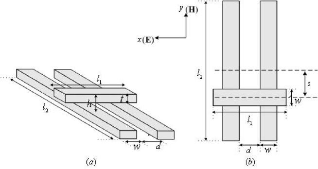
As described in Ref. 11, each unit cell consists of an upper gold strip as a bright mode and a lower pair of gold strips as a dark mode with a dielectric spacer, as shown in Fig. 1. In particular, the parameter is defined to depict the lateral displacement. Either the symmetry or the asymmetry is expressed as or , respectively. The plasmonic EIT originates from the coupling of the two modes when the symmetry is broken.LiuNM2009 ; SinghPRB2009 ; MaierNM2009 Essentially, the former serves as an optical dipole antenna, and the latter as a quadrupole antenna, when light is illuminated perpendicularly and the electric field of the light is parallel to the upper strip. Our study is limited to investigation of the symmetric structure, and the similar geometrical parameters are used with two major differences. One is that the dielectric spacer and the substrate are not taken into account for simplicity, i.e., they are treated as air, which does not affect the EIT-like feature except for a blueshift. It does not cause any loss of generality in the discussion afterwards. The other is that the lower pair of gold strips is elongated to 790 nm, about two times longer than that in Ref. 11. The reason for this elongation will be explained later. The numerical calculation is carried out by using a finite-integration package, CST Microwave Studio. The permittivity of gold is described by the Drude model with a plasmon frequency of rad/s and a collision frequency of Hz, which is three times larger than that in bulk gold. LiuNM2009 ; DollingSci2006
Figure 2 displays the simulated transmission and absorption spectra for the symmetric structures with the different vertical distance . The latter is calculated according to , where and denote the transmission and the reflection, respectively. Astonishingly, the EIT-like feature completely disappears when the length of the lower pair is relatively short, nm, without varying the other parameters. In contrast, this feature clearly manifests around 240 THz if the lower pair is elongated to 790 nm without any other variations. In other words, whether the plasmonic EIT can be excited or not depends on the length of the lower pair, rather than the structural asymmetry. This appears inconsistent with the conclusion in Ref. 11, where it is believed that the coupling fades away owing to the structural symmetry. Therefore, to solve this puzzle, what the coupling is and how the coupling works must be deciphered. Lu et al.Lu2009 provided a physical picture for plasmonic EIT, in which it is considered as a result of plasmonic coherent interference in near-field zone based on the excitation of surface plasmon polaritons (SPPs) and MPR. The former is formed on the upper strip since it behaves as an optical dipole antenna,NovotnyPRL2007 while the latter is induced by the magnetic component of dipole fields. According to this picture, the disappearance of the EIT-like effect can be explained by the fact that the magnetic components have the same magnitudes in opposite directions on the both sides of the upper strip if the structure is symmetric and thus the induced currents cancel each other out. Despite their opposite directions, the two magnetic components cannot be equal in the absence of symmetry so as to produce the current or quadrupole in the lower pair. This means that the pivot of the plasmonic EIT is determined by whether the lower pair (i.e., dark mode) is excited or not.
The point of importance is that the quadrupole can not in general be excited by normal incidence because of its vanishing dipole moment (i.e., it is dark). To activate it, a highly angled illumination must be resorted to.Zhang2008PRL ; MaierNM2009 As shown in Fig. 3, two dark modes were magnetically excited at 120 and 240 THz when the plane wave irradiates on the elongated pair (790 nm) along the -y direction, without symmetry breaking of both the incident field and the structure itself. The latter frequency is twice as high as that of the former, which can be ascribed to be the second-order MPR.SheridanAPL2007 The second resonant peak at 240 THz was located coincidentally at the plasmonic EIT peak as shown in Fig. 2. Therefore, on the basis of this physical picture, the lower pair is excited explicitly at 240 THz.
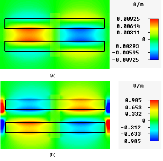
If we take a closer look at the z-component distribution of the magnetic field at the frequency of plasmonic EIT, as the physical picture describes, it is unambiguous that the magnetic fields point in and out of x-y plane on both sides of the upper strip [see Fig. 4(a)]. Since there is the fact that the magnetic field is out of phase with the electric field,Lu2009 ; BurresiScience2009 the y-component distribution of the electric field is illustrated in Fig. 4(b) with a phase difference compared to the magnetic one, where the dark mode is activated and two antisymmetric quadrupolar resonances are induced on both sides of the upper pair by two antisymmetric magnetic fields of dipole fields. Duo to the excitation of the two circular currents, the plasmonic EIT was also achieved in the symmetric structures. Because the length of the lower pair was elongated, more room is provided to accommodate the two circular currents thereby avoiding canceling each other out. Consequently, the second-order MPR is excited so that the plasmonic EIT can appear even in the symmetric structures (see Fig. 2). This possibility was not even considered as a candidate for plasmonic EIT.
Furthermore, as shown in Fig. 3, the intensity of the second-order MPR is larger than that of the fundamental mode so as to broaden the FWHM of the plasmonic EIT peak compared with that in Ref. 11. It is generally believed that the strongly coupling renders the larger FWHM.TassinPRL2009 On the other hand, the strength of the coupling can be tuned by adjusting the vertical distance . The larger the vertical distance, the smaller the FWHM, of course, at the cost of transmission.
In conclusion, it is possible for the plasmonic EIT to be realized even in symmetric structures. This is determined by whether the MPR can be excited or not, which clarifies the puzzle of the essence of coupling and strongly validates the mechanism of plasmonic EIT. Essentially, symmetry or asymmetry is not the pivot of the plasmonic analogue of EIT, but the MPR is. The resembling modification was not carried out on the upper strip at the moment because the frequency scaling law of SPPs is more complicated than that of MPR arising from the phase shift.STPRB2008 The point of great interest is that the optical response is invariant, whereas the restrictions on size are partly relaxed, and thus the fabrication is much easier.
Yuehui Lu would like to express his gratitude to Nguyen Thanh Tung for valuable discussions. This work was supported by the MEST/NRF through the Quantum Photonic Science Research Center, Korea and by the Research fund of HYU (HYU-2008-T).
References
- (1) K.-J. Boller, A. Imamoǧlu, and S. E. Harris, Phys. Rev. Lett. 66, 2593 (1991).
- (2) S. E. Harris, Phys. Today 50, 36 (1997).
- (3) M. Fleischhauer, A. Imamoglu, and J. P. Marangos, Rev. Mod. Phys. 77, 633 (2005).
- (4) M. D. Lukin, S. F. Yelin, and M. Fleischhauer, Phys. Rev. Lett. 84, 4232 (2000).
- (5) S. E. Harris and L. V. Hau, Phys. Rev. Lett. 82, 4611 (1999); D. Budker, D. F. Kimball, S. M. Rochester, and V. V. Yashchuk, ibid. 83, 1767 (1999).
- (6) C. L. G. Alzer, M. A. G. Martinez, and P. Nussenzveig, Am. J. Phys. 70, 37 (2002).
- (7) T. Opatrný and D.-G. Welsch, Phys. Rev. A64, 023805 (2001); D. D. Smith, H. Chang, K. A. Fuller, A. T. Rosenberger, and R. W. Boyd, ibid. 69, 063804 (2004); A. Naweed, G. Farca, S. I. Shopova, and A. T. Rosenberger, ibid. 71, 043804 (2005); L. Maleki, A. B. Matsko, A. A. Savchenkov, and V. S. Ilchenko, Opt. Lett. 29, 626 (2004); Q. Xu, S. Sandhu, M. L. Povinelli, J. Shakya, S. Fan, and M. Lipson, Phys. Rev. Lett. 96, 123901 (2006).
- (8) S. Zhang, D. A. Genov, Y. Wang, M. Liu, and X. Zhang, Phys. Rev. Lett. 101, 047401 (2008).
- (9) H. Xu, and B. S. Ham, arXiv:0905.3102v4 [quant-ph].
- (10) Y. Lu, H. Xu, N. T. Tung, J. Y. Rhee, W. H. Jang, B. S. Ham, and Y. P. Lee, arXiv:0906.4029v4 [cond-mat.mtrl-sci].
- (11) N. Liu, L. Langguth, T. Weiss, J. Kästel, M. Fleischhauer, T. Pfau, and H. Giessen, Nature Mater. 8, 758 (2009).
- (12) N. Papasimakis, V. A. Fedotov, N. I. Zheludev, and S. L. Prosvirnin, Phys. Rev. Lett. 101, 253903 (2008); N. Papasimakis, Y. H. Fu, V. A. Fedotov, S. L. Prosvirnin, D. P. Tsai, and N. I. Zheludev, Appl. Phys. Lett. 94, 211902 (2009).
- (13) P. Tassin, L. Zhang, T. Koschny, E. N. Economou, and C. M. Soukoulis, Phys. Rev. Lett. 102, 053901 (2009); Opt. Express 17, 5595 (2009).
- (14) R. Singh, C. Rockstuhl, F. Lederer, and W. L. Zhang, Phys. Rev. B79, 085111 (2009).
- (15) V. Yannopapas, E. Paspalakis, and N. V. Vitanov, Phys. Rev. B80, 035104 (2009).
- (16) E. Prodan, C. Radloff, N. J. Halas, and P. Nordlander, Science 302, 419 (2003).
- (17) F. Hao, Y. Sonnefraud, P. V. Dorpe, S. A. Maier, N. J. Halas, and P. Nordlander, Nano Lett. 8, 3983 (2008).
- (18) G. Dolling, C. Enkrich, M. Wegener, C. M. Soukoulis, and S. Linden, Science 312, 892 (2006); S. Zhang, W. J. Fan, K. J. Malloy, S. R. J. Brueck, N. C. Panoiu, and R. M. Osgood, J. Opt. Soc. Am. B 23, 434 (2006).
- (19) L. Novotny, Phys. Rev. Lett. 98, 266802 (2007).
- (20) S. A. Maier, Nature Mater. 8, 699 (2009).
- (21) A. K. Sheridan, A. W. Clark, A. Glidle, J. M. Cooper, and D. R. S. Cumming, Appl. Phys. Lett. 90, 143105 (2007).
- (22) M. Burresi, D. van Oosten, T. Kampfrath, H. Schoenmaker, R. Heideman, A. Leinse, and L. Kuipers, Science 326, 550 (2009).
- (23) T. Søndergaard, J. Beermann, A. Boltasseva, and S. I. Bozhevolnyi, Phys. Rev. B77, 115420 (2008).
Figure captions
Fig. 1. (a) Three-dimensional view and (b) two-dimensional view of the unit cell. The geometric parameters are nm, nm, nm, nm, and . The vertical distance between the upper gold strip and the lower pair of gold strips is denoted to be and the thickness of each strip, , is 40 nm. The periods of structure is 870 nm in both the x and y directions. The incident plane wave irradiates along the z direction and its electric component, E, is parallel to the x direction.
Fig. 2. (color online) (a) Transmission and (b) absorption spectra with various vertical distances . The black curves in (a) and (b) are obtained with the same parameters ( nm) except nm.
Fig. 3. (a) Schematics for the incident plane wave on the lower pair of gold strips ( nm), where the wave is parallel to the strips and its electric field along the x direction. The arrow is an probe placed 10 nm away from the center of the end facet. (b) Spectral response of the probe.
Fig. 4. (a) z-component distribution of magnetic field at the frequency of plasmonic EIT with nm, where the phase is . (b) The y-component distribution of electric field at the same frequency, where the phase is .
![[Uncaptioned image]](/html/0911.2062/assets/x2.png)
![[Uncaptioned image]](/html/0911.2062/assets/x4.png)