Cavity QED with separate photon storage and qubit readout modes
Abstract
We present the realization of a cavity quantum electrodynamics setup in which photons of strongly different lifetimes are engineered in different harmonic modes of the same cavity. We achieve this in a superconducting transmission line resonator with superconducting qubits coupled to the different modes. One cavity mode is strongly coupled to a detection line for qubit state readout, while a second long lifetime mode is used for photon storage and coherent quantum operations. We demonstrate sideband based measurement of photon coherence, generation of photon Fock states and the scaling of the sideband Rabi frequency with using a scheme that may be extended to realize sideband based two-qubit logic gates.
pacs:
03.67.Lx, 03.67.Bg, 42.50.Pq, 85.25.-jIn cavity quantum electrodynamics (QED) Walther2006 ; Haroche2007 ; Ye2008 the interaction between matter and light confined in a cavity is studied. The lifetime of a photon in a cavity can be engineered by changing the transparency of the cavity mirrors. One way to carry out experiments with photons of different lifetimes would be to use two different cavities, for example in a crossed Fabry-Perôt geometry (see Fig. 1). Here we demonstrate a method of doing such experiments by instead controlling the quality factors of different harmonic modes of a single cavity, in an electrical implementation of cavity QED known as circuit QED Wallraff2004 ; Schoelkopf2008 . In circuit QED very large coupling strengths can be achieved between macroscopic superconducting qubits and a strongly confined microwave field in an on-chip transmission line resonator Wallraff2004 ; Schoelkopf2008 . This has formed the basis of remarkable recent progress in quantum information processing (QIP) Dicarlo2009 ; Ansmann2009 and quantum optics Houck2007 ; Fink2008 ; Schuster2007 ; Hofheinz2008 ; Fink2009 ; Hofheinz2009 ; Bishop2009 with superconducting circuits. The quasi one-dimensional cavity in this system allows for a novel geometry to be used here that is unavailable in conventional optical or microwave frequency cavity QED.
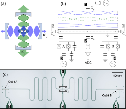
The lifetime of resonator photons in circuit QED is controllable via capacitive coupling of input and output transmission lines at the resonator ends Goeppl2008 . Here we instead couple input/output lines at the resonator center. A circuit schematic and optical image of the device with two embedded superconducting transmon qubits Koch2007 ; Schreier2008 are shown in Fig. 1 (b and c). The first harmonic and other even-symmetry modes have an electric field antinode at the center, and are hence strongly coupled to the center ports 1 and 2. Conversely, the fundamental and higher odd-symmetry harmonic modes have an electric field node at the center of the resonator and couple only weakly to the center ports BondNote . Choice of the capacitance between the resonator center and the external lines allows one to define an external quality factor (Q), at the even resonator modes, leaving the Q factor of the odd modes almost unaffected, and limited only by internal losses. Embedding superconducting qubits into such a device allows us to perform cavity QED experiments with two radically different photon lifetimes in the same resonator.
A transmission measurement through a strongly coupled resonator mode can be used to perform a quantum non-demolition measurement of a qubit detuned from the resonator Wallraff2005 . This technique has been extended to perform simultaneous joint readout and complete tomography of two qubits Filipp2009 and has also been used for readout in the realization of two-qubit quantum algorithms Dicarlo2009 . For this dispersive measurement to be efficient the cavity lifetime should be dominated by coupling into the detector port rather than by internal loss and much shorter than the qubit lifetimes to gain information about the qubit states before relaxation occurs Gambetta2008 .
This requirement can often be counter to a desire for maximized photon lifetimes for cavity QED and QIP experiments. An example of this trade-off occurs when one wishes to use photons to remotely couple two qubits, by for example tuning qubits into resonance with a cavity Hofheinz2009 ; Ansmann2009 , or via resonant sideband transitions Leek2009 . The fidelity of entangled qubit states generated using sideband transitions in our own experiments has so far been limited by a photon lifetime chosen to also allow efficient qubit measurement Leek2009 . The problem can be solved if additional circuitry separate from the coupling resonator is used for measurement, either in the form of individual qubit readouts Ansmann2009 ; Mallet2009 , or a separate joint readout resonator. However, utilizing the multiple harmonic modes of a single resonator and engineering their Q factors represents a viable solution which enables the coupling of two or more qubits to both modes simultaneously with little increase of circuit complexity.
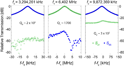
For initial assessment of the center coupling concept, a device (I) was fabricated with weakly capacitively coupled end ports 5 and 6 (see Fig. 1b) but without qubits. The capacitances were chosen small enough () to have little effect on the quality factor of the first three harmonic modes, while the center ports were strongly coupled (). Measurements of these first 3 harmonics are shown in Fig. 2. The data is normalized to a resonant transmission of in each case. The center coupled transmission (, green) shows a resonance at with quality factor (Fig. 2b) consistent with the chosen value of , but low transmission around and . The end-coupled transmission (, blue) displays resonances at (a), and (c) with much higher measured quality factors and respectively Qnote , and low transmission at (b). These Q factors are on the same order as those measured for weakly end-coupled two-port resonators Oconnell2008 ; Goeppl2008 , showing that the fundamental and 2nd harmonic in the 4-port device are negligibly coupled to the center ports. Hence the device performs as desired, with the first harmonic strongly coupled to the outside world for qubit readout, and the odd modes well isolated for optimal photon storage times.
A second device (II) fabricated with a transmon qubit at each end of the resonator (see Fig. 1c) was used for all further experiments. This device has higher mode frequencies than device A, and no end ports (5 and 6). The qubits both have a charging energy , a maximum Josephson energy , and flux tunable transition frequencies to a maximum of around . Direct microwave drive lines (ports 3 and 4) allow selective driving of the individual qubits.
The resonant coupling strengths of the qubits to the 1st harmonic at were extracted from a standard resonator transmission measurement of the vacuum Rabi mode splitting Wallraff2004 ; Fink2009 , using a locally coupled flux bias coil to tune the qubit frequency. The coupling strength to the 2nd harmonic at was instead obtained from a spectroscopic measurement of the qubit transition frequency Schuster2005 . In this dispersive measurement the phase shift of a fixed frequency tone at the first harmonic of the resonator was monitored as the transition frequency of each qubit was swept across the 2nd harmonic resonance frequency of the resonator.
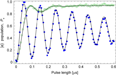
To demonstrate the functionality of the device, we couple the qubits to the different cavity modes using sideband transitions Wallraff2007 . We carry out experiments in the dispersive regime in which the qubits are far detuned from both modes. The qubit population is in all cases extracted from a dispersive measurement at the 1st harmonic of the resonator Bianchetti2009 . We first tune one qubit (A) to a transition frequency of , at a detuning below the 1st harmonic. We then drive the two photon blue sideband with a microwave field applied to port 3 and observe Rabi oscillations between the states and , where and are the ground and first excited states of the qubit respectively, and refer to the photon number in the resonator mode (see Fig. 3) Leek2009 . The rapidly decaying Rabi oscillations fit well to a master equation simulation, with a short photon lifetime of that is consistent with the linewidth of the resonator spectrum. The sideband drive rate is extracted as . Since is much shorter than the qubit lifetime , the qubit excited state population saturates at long times at , an effect that efficiently creates population inversion Leek2009 . An equivalent experiment is then carried out with the qubit at a transition frequency of , at the same detuning but this time below the 2nd harmonic. The drive rate in this case was and the qubit lifetime . High contrast sideband Rabi oscillations are observed in this case due to the much longer photon lifetime in this cavity mode.
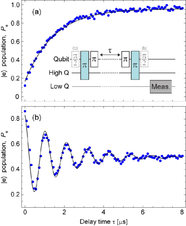
Using a sequence of blue sideband and direct qubit pulses, we now demonstrate a photon storage experiment with the long lifetime mode. The system is first excited to the state using a blue sideband -pulse. A direct -pulse on the transition returns the qubit to the ground state and leaves the resonator in a single photon Fock state . After a storage time , the two pulses are repeated in reverse order. For perfect photon storage the qubit population should return to state . However, when the photon is lost the qubit ends up in state . The measured result is shown in Fig. 4(a), along with a master equation simulation fitted to the data, with a photon lifetime of , close to the value found from the sideband Rabi data in Fig. 3. This corresponds to a quality factor of . We also measure the photon dephasing time using a Ramsey type pulse sequence (Fig. 4(b)), finding . The fact that indicates the presence of some fluctuation of the resonator frequency, which may be partially accounted for by the dispersive coupling to the qubit, which at the chosen transition frequency has a separately measured dephasing time of . The excellent coherence properties of such a long lived cavity mode could enable its use as a quantum memory, collectively accessible to multiple qubits.
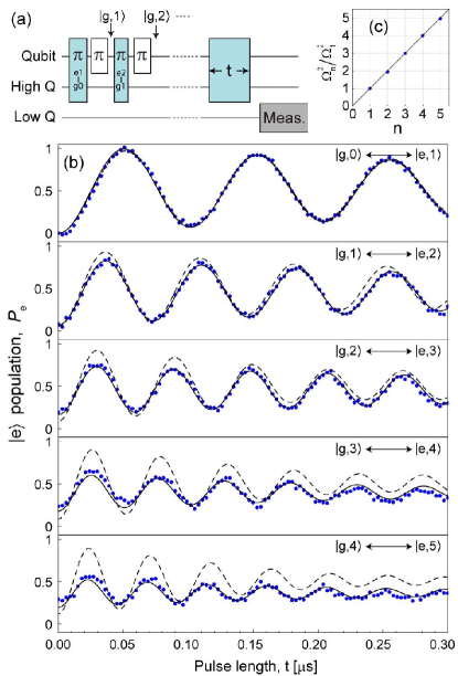
The high Q of the 2nd harmonic also allows us to carry out more complex sideband pulse sequences to generate Fock states of the long-lived microwave field, and to observe Rabi oscillations on the blue sideband between the states and up to (see Fig. 5). The state is generated by applying a sideband -pulse followed by a direct qubit -pulse and repeating times (see Fig. 5a). In Fig. 5b we show the results of sideband Rabi oscillation experiments starting from the experimentally generated Fock states with . A fit to yields Rabi frequencies that are in very close agreement with the expected scaling of the coupling strength (see Fig. 5c) Fink2008 ; Hofheinz2008 . Master equation simulations are also shown in Fig. 5b, agreeing qualitatively with the measured data, but deviating for the longer pulse sequences. This is likely due to build up of errors due to off-resonant driving of other transitions, and will be important to characterize and correct before taking operation complexity further in future experiments. A good understanding of these higher sideband transitions should allow their use as the basis of a universal two-qubit gate SchmidtKaler2003 .
An attractive feature of the two-mode device is the possibility to carry out joint dispersive measurement and photon based operations on two qubits coupled to both modes simultaneously, a task that would be more difficult with multiple cavities. In order to demonstrate this, we have generated Bell states between two qubits in this device using a sideband scheme Leek2009 , and characterized the resulting states using state tomography Filipp2009 . Measured states were found to have fidelities of and and concurrence Horodecki2008 and with respect to the ideal states and . The fidelity of the prepared states is now not limited by photon lifetime but rather by the the length of the entangling sideband pulses relative to the qubit dephasing times. Shorter side band pulses would require higher drive rates, that are observed to lead to off-resonant driving of direct qubit transitions reducing the fidelity of the prepared states. This aspect will likely be improved in future experiments using optimal control techniques.
In conclusion, we have realized a microwave frequency on-chip resonator for cavity QED experiments with photon lifetimes in adjacent harmonic modes differing by a large factor. We have demonstrated photon storage, Fock state and Bell state generation with long lived photons of one mode, while carrying out efficient dispersive qubit readout using short lived photons in a second mode. Such mode lifetime engineering enables increased flexibility in the use of harmonic modes for qubit-qubit coupling in superconducting circuits, and in the control of decoherence in such systems. The concept could thus be useful in the design of future quantum information processors.
We thank A. Blais for valuable discussions and comments on the manuscript. We acknowledge the group of M. Siegel at the University of Karlsruhe for the preparation of Niobium films. This work was supported financially by the Swiss National Science Foundation, by the EC via the EuroSQIP project and by ETH Zurich.
References
- (1) H. Walther, B. T. H. Varcoe, B.-G. Englert and T. Becker, Rep. Prog. Phys. 69, 1325 (2006).
- (2) S. Haroche and J.-M. Raimond, Exploring the Quantum: Atoms, Cavities and Photons (Oxford University Press, Oxford, 2007).
- (3) J. Ye, H. J. Kimble and H. Katori, Science 320, 1734 (2008).
- (4) A. Wallraff et al., Nature (London) 431, 162 (2004).
- (5) R. J. Schoelkopf and S. M. Girvin, Nature (London) 451, 664 (2008).
- (6) L. DiCarlo et al., Nature (London) 460, 240 (2009).
- (7) M. Ansmann et al., Nature (London) 461, 504 (2009).
- (8) A. A. Houck et al., Nature (London) 449, 328 (2007).
- (9) J. M. Fink et al., Nature (London) 454, 315 (2007).
- (10) D. I. Schuster et al., Nature (London) 445, 518 (2007).
- (11) M. Hofheinz et al., Nature (London) 454, 310 (2008).
- (12) J. M. Fink et al., Phys. Rev. Lett. 103, 083601 (2009).
- (13) M. Hofheinz et al., Nature (London) 459, 546 (2009).
- (14) L. Bishop et al., Nature Phys. 5, 105 (2009).
- (15) M. Göppl et al., J. Appl. Phys. 104, 113904 (2008).
- (16) J. Koch et al., Phys. Rev. A 76, 042319 (2007).
- (17) J. Schreier et al., Phys. Rev. B 77, 180502R (2008).
- (18) To avoid disruption of the odd mode fields, the ground planes must be well connected across the center ports, achieved here with bond wires.
- (19) A. Wallraff et al., Phys. Rev. Lett. 95, 060501 (2005).
- (20) S. Filipp et al., Phys. Rev. Lett. 102, 200402 (2009).
- (21) J. Gambetta et al., Phys. Rev. A 77, 012112 (2008).
- (22) P. J. Leek et al., Phys. Rev. B 79, 180511R (2009).
- (23) F. Mallet et al., Nature Phys. 5, 791 (2009).
- (24) Note that the high quality resonances are here measured at an input power such that the resonator photon populations on resonance are . At low photon numbers (), the Q drops to around , an effect which is also seen in 2-port devices Oconnell2008 .
- (25) A. D. O’Connell et al., Appl. Phys. Lett. 92, 112903 (2008).
- (26) D. I. Schuster et al., Phys. Rev. Lett. 94 123602 (2005).
- (27) A. Wallraff et al., Phys. Rev. Lett. 99, 050501 (2007).
- (28) R. Bianchetti et al., Phys. Rev. A 80, 043840 (2009).
- (29) F. Schmidt-Kaler et al., Nature (London) 422, 408 (2003).
- (30) R. Horodecki, P. Horodecki, M. Horodecki and K. Horodecki, Rev. Mod. Phys. 81, 865 (2009).