Conductance Through a Redox System in the Coulomb Blockade Regime: Many-Particle Effects and Influence of Electronic Correlations
Sabine Tornow
Institut für Mathematische Physik, TU Braunschweig, 38106 Braunschweig, Germany
Gertrud Zwicknagl
Institut für Mathematische Physik, TU Braunschweig, 38106 Braunschweig, Germany
Abstract
We investigate the transport characteristics of a redox system weakly coupled to leads in the Coulomb blockade regime. The redox system comprises a donor and acceptor separated by an insulating bridge in a solution. It is modeled by a two-site extended Hubbard model which includes on-site and inter-site Coulomb interactions and the coupling to a bosonic bath. The current voltage characteristics is calculated at high temperatures using a rate equation approach. For high voltages exceeding the Coulomb repulsion at the donor site the calculated transport characteristics exhibit pronounced deviations from the behavior expected from single-electron transport. Depending on the relative sizes of the effective on-site and inter-site Coulomb interactions on one side and the reorganization energy on the other side we find negative differential resistance or current enhancement.
pacs:
71.27.a, 34.70.e, 82.39.Jn
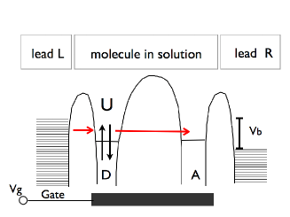
Figure 1: Schematic view of the redox system with donor (D) and acceptor (A) coupled to the leads L and R. The electronic degrees of freedom of the DA system are coupled to the environment comprising internal vibrations and the solvent dynamics. The current is calculated as a function of the bias voltage and gate voltage .
Electron transfer is fundamental in chemistry and biology.
In a polar environment the redox process involves strong coupling to the underlying nuclear motion and is usually dominated by the nuclear reorganization that accompanies the charge rearrangement. Such a redox system contacted to leads can serve as a component of molecular electronic devices RatnerAviram . Recent experiments Tao showed that the electron transport in redox systems depends strongly on the environment (solvent) and can be described by a thermally activated electron transfer process mediated by thermal fluctuations of the environment.
Although the standard description focuses on single-electron transfer Transfer multiple electron transfer is the dominant process in some chemical systems Evans ; Two ; May .
Many-particle states have to be taken into account and the rate between these states depends strongly on the Coulomb interaction Tornow .
Contacting such a redox-system to leads and applying a voltage larger than the effective on-site Coulomb repulsion, e.g., on the donor, it can be occupied by multiple electrons. Then the single-electron picture breaks down and the transport is affected by electron correlations Ghosh ; Parida . In the present paper, we study the current through such a redox sytem taking the solvent explicitly into account for the first time. The central results are displayed in Fig.˜2 and Fig.˜3 where negative differential resistance (NDR) or current enhancement is be found, respectively.
These effects occur at voltages when multiple electrons populate the DA system.
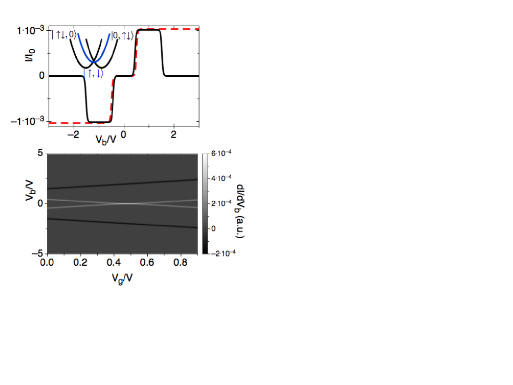
Figure 2: (color online) Current as a function of for and (upper panel, black solid line) in comparison to the case of independent electrons (upper panel, red dashed line) as well as a contour plot of vs. and for correlated electrons (lower panel). The other parameters see in the text. Inset: Potential surfaces for the states: , and . Figure 3: (color online) Current as a function of for and (upper panel, black solid line) in comparison to the case of independent electrons (upper panel, red dashed line) as well as a contour plot of vs. and for correlated electrons (lower panel). The other parameters see in the text. Inset: Potential surfaces for the states: , and . Note that in this case the transfer from to is in the activation-less regime.
We consider a two-site model where the redox system comprises donor (D) and acceptor (A) which are separated by an insulating bridge (see Fig. 1). The system is embedded in a solvent and weakly coupled to metallic electrodes. The Hamiltonian is given by where the DA system is described by
(1)
As written and denote annihilation
and creation operators for fermions with spin in an orbital
localized at site and is the number-operator. The first four terms correspond to an extended
two-site Hubbard model, with on-site energies , hopping
matrix element , on-site Coulomb repulsion , and inter-site Coulomb repulsion .
The two last parts describe the electron-boson coupling (in the standard polaron form) and the free bosonic bath with boson creation and annihilation operators and , respectively. Furthermore, the coupling between leads and DA system is given by
(2)
while the dynamics of the free fermions in the leads is accounted for by
.
In the following, we focus on the Coulomb blockade regime with weak coupling between leads and DA system which is strongly coupled to the bosonic bath. The electrons tunnel sequentially on and off as well as migrate via thermal activation through the DA system. At high temperatures, exceeding the activation energy, Marcus approximation is valid where only one bosonic mode with frequency is considered Tornow . We obtain an effective model where the parameters are renormalized according to: , (with the reorganization energy , and .
The DA-system has 16 basis-states describing the occupation on D (A),
with different number of electrons where is the number of electrons on D (A): ,, , ,, , ,, , , ,, and .
Assuming fast dephasing and incoherent transfer the population dynamics can be described by kinetic equations:
(3)
where is the probability that the system is in state and
is the
rate of the transition from state to state which is specified in the following. If the occupation is changed by one at fixed the rate is
(4)
For the reverse process we find
(5)
The hybridization strength is assumed to be energy independent and equal for R and L, is the Fermi distribution and is the density of states of the leads. We assume . Similar rates are obtained if is changed and is constant by exchanging with and with . The chemical potential of the lead L and R is defined
with , where is the bias voltage. A finite gate voltage leads to and .
The transfer rates, at conserved particle number , is given by the Marcus theory in the nonadiabatic limit ()
(6)
(7)
where the Franck-Condon integral
(8)
depends on the energy difference between state
and and the corresponding
reorganization energy , e.g., , and
We calculate the stationary current () as a function of bias voltage and gate voltage
as
(9)
by assuming , and
for the parameters , , , . The current depends on the rate of electron transfer from D to A. Neglecting electron correlations two electrons on D are transferred each with a single-particle Marcus rate. However, electron correlations have to be taken into account (even for ) for a correct description, e.g., the rate for depends exponentially on .
In Fig.˜2 and Fig.˜3 (upper panel) we display for and , respectively, in comparison to the current where electron correlations are neglected (red dotted line) for .
For both curves are identical but at two electrons occupy D. The electrons are transferred via a transition from state to , or . The potential surfaces for these many-particle states are displayed in the inset. In Fig.˜2 the transfer is in the normal regime and in Fig. 3 in the activation-less regime since . In the latter case the current is enhanced for by a factor of 10000 in comparison to the uncorrelated case. For the transfer is in the normal or inverted region and negative differential resistance (NDR) is present as seen in Fig.˜2 (lower panel).
For our parameters () the current is surpressed by a factor of 20.
Furthermore, we examined a small dependency of the on-site energies on and found that the results do not change qualitatively.
In summary, we considered a solvated redox system weakly coupled to leads at high temperatures which is able to accept more than one electron. If the bias voltage is larger than the effective Coulomb repulsion, the donor can be occupied by two electrons and the transfer rates are dominated by correlation effects. We found that the current strongly depends on the difference between the on-site and inter-site Coulomb repulsion as well as the reorganization energy. The current is enhanced in the activation-less regime when the difference is zero, otherwise NDR behavior is obtained.
Acknowledgment
This research was supported by the State of Lower-
Saxony and the VolkswagenFoundation. We are grateful to A. Nitzan for helpful discussions.
References
(1) A. Aviram etal., Chem. Phys. Lett., 29, 277 (1974).
(2) X. Li etal., JACS, 129, 11535 (2007).
(3) R. A. Marcus, Rev. Mod. Phys., 65, 599 (1993).
(4) D. H. Evans, Chem. Rev., 108, 2113 (2008).
(5) L. D. Zusman etal., J. Chem. Phys., 105, 165 (1996).
(6) E. G. Petrov et al., Phys. Rev. E, 68, 061916 (2003).
(7) S. Tornow etal., Phys.Rev. B, 78, 035434 (2008).
(8) B. Muralidharan etal., J. Phys.: Cond. Mat., 20, 374109 (2008).
(9) P. Parida etal. J. Phys.: Cond. Mat., 21, 095301 (2009).