Capillary force-induced structural instability in liquid infiltrated elastic circular tubes
Abstract
The capillary-induced structural instability of an elastic circular tube partially filled by a liquid is studied by combining theoretical analysis and molecular dynamics simulations. The analysis shows that, associated with the instability, there is a well-defined length scale (elasto-capillary length), which exhibits a scaling relationship with the characteristic length of the tube, regardless of the interaction details. We validate this scaling relationship for a carbon nanotube partially filled by liquid iron. The capillary-induced structural transformation could have potential applications for nano-devices.
pacs:
68.08.De, 46.32.+x, 61.48.DeA wide range of phenomena in nature, which span from everyday observations to many bio-related processes, are a result of capillary forces. Common examples include the shape of liquid droplets, the imbibition of a sponge deGennes03 , the clumping of wet hair into bundles Bico04 and coalescence of paintbrush fibers Kim06 , the standing of aquatic insects on water Hu05 , and lung airway closure etc Heil08 . Recently it was found that capillary forces can induce structural deformations or instability in an elastic system, in cases where these surface forces are comparable in magnitude to bulk elastic forces. More importantly, there is a well-defined length scale (elasto-capillary length ) which underlies such structural instabilities Cohen03 , which usually reveals an intrinsic scaling relation with the characteristic dimensions Cohen03 ; Bico04 ; Kim06 ; py07 ; Huang07 ; Neukirch07 . The elasto-capillarity deformation or instability has been also found to have many interesting applications Chakrapani04 ; py07 ; Huang07 ; Pokroy09 .
Liquid infiltrated elastic tubes are common in bio-systems and everyday life. When the capillary forces are comparable to the bending stiffness of the tube, the tube can be deformed or become unstable at some critical filling fraction. Whether the instability can be associated with a new type of scaling relationship has thus far remained relatively unexplored. In this work, molecular dynamics (MD) simulations of this phenomenon are coupled with theoretical analysis to investigate this issue for an elastic cylindrical tube partially filled by a liquid. Our results show that the instability or deformation of a flexible tube leads to a well-defined scaling law regardless of the interaction details. Our MD simulations on liquid iron encapsulated by carbon nanotubes quantitatively demonstrate the scaling law.
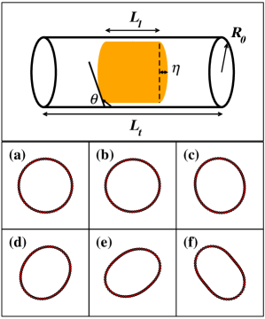
We consider an elastic circular tube with length of and radius of partially filled with an incompressible Newtonian liquid of length , where refers the radius of the “dry” tube without any compression. The upper panel of Fig. 1 illustrates the model used in the current work. The energy of the system can be written formally as,
| (1) |
where , and are the elastic bending strain energy, elastic compression strain energy, and interfacial free energy (capillary energy), respectively. In the continuum elasticity picture Landau96 ; Timoshenko88 , the bending strain energy is , and the compression strain energy is , where denotes the curvilinear integral along the perimeter of the cross section and is the perimeter of the original tube cross section. The bending stiffness and the compression stiffness are constants related to Young’s modulus , the Poisson ratio , and the tube thickness . The local radius of curvature is denoted as . The interfacial free energy is, , where , and are the areas of liquid-vapor, solid-liquid and solid-vapor interfaces, respectively, is the perimeter of the cross section and , here we have included the solid-vapor surface outside the cylinder that is not covered by liquid. The surface and interface free energies are denoted , and , for the liquid-vapor, solid-liquid and solid-vapor interfaces, respectively. The specific free energy of the three-phase contact line (i.e., the line tension) is denoted as .Boruvka77 The term usually can be neglected if the dimension of the system is not too small.
Since only near-critical sizes (where the circular shape is near its stability limit) are considered, the non-circular shape is approximated by that of an ellipse. For an ellipse with long axis and short axis , the shape can be described well by introducing two independent variables, and , which are defined as and . When =1, these variables describe a perfect circle. By introducing two integrals, with and , we can write and Sun04 Finally we have
| (2) |
In order to calculate the capillary energy, the area of the interfaces should be written in explicit forms. However, the general calculation of the liquid-vapor interface, which is a meniscus, for arbitrary tube shape is beyond the scope of the present treatment and will be discussed in a subsequent paper Yang09 . To elucidate the important physics as well as to simplify the mathematical treatment, we consider the cases where the contact angles are close to . Within this limitation, all the interface areas can be defined without ambiguity. It should be noted that in the simulations discussed below, the solid-liquid contact angles are in fact approximately .
Thermal fluctuations of the tubes are neglected as they exist on a length scale comparable to the persistence length(, and Y: Young’s modulus, I: the area moment of intertia. ), which usually is much longer than the characteristic length of system. For example, in single-walled carbon nanotubes, the persistence length is on the order of 45 Cohen03 . With the above assumptions as well as the assumption of that the liquid is incompressible, we can write , and . So, the interfacial free energy is,
| (3) |
In Eq. 2, the elastic energy always tends to maintain the tube in a circular shape. If the capillary energy approaches or exceeds the magnitude of the elastic energy, the circular shape will be unstable and the system might seek a lower energy state. Physically, the deformation of the tube reduces the interfacial energy at the cost of increasing the elastic energy. For , , the system could deform to increase the area of the solid-liquid interface. Even for , , the tube still has a chance to deform if the first term exceeds the second term in Eq. 3, in which case the area of the liquid-vapor interface decreases. The MD simulations in the current work focus on the latter case. The critical transition point can be located by the condition . And the radius of tube at the critical point () is determined by . Remembering , and the above conditions produce the critical relation,
| (4) |
where is the critical length of the tube. For elastic tubes, if the compression stiffness () is much larger than the bending stiffness , which is the the case we are interested in, one can neglect the different between and ,
| (5) |
We can define an effective interface free energy , where the factor in reflects an inherent geometric relation among the three interfaces. Note that if is divided , according to Eq. 5, a generalized pressure can be obtained, which is the same form as reported in Ref. Sun04 for CNTs under pressure. In fact, this capillary force can be regarded as a kind of negative internal pressure. From Eq. 5, a generalized elasto-capillary scaling relation can be derived.
| (6) |
Similar to previous studies, Cohen03 ; Bico04 ; Kim06 ; py07 ; Huang07 ; Neukirch07 we can define an elasto-capillary length () for this system, which gives the typical effective curvature induced by capillarity on the tube. Different from previous studies, the elasto-capillary length is not simply defined in terms of interfacial free energies, but rather an effective (average) interface free energy (). The difference stems from the fact that in the filled liquid tube system studied here, the area of the solid-liquid (solid-vapor) and liquid-vapor interfaces changes in different ways (amounts) as the tube is deformed. The former scales as R, while the later scales as . It implies that the average capillary forces depend on the system size itself ( in reflects the dependence). However in previous studies, either the three interfaces change simultaneously by the same amount (liquid drop on thin films)py07 ; Huang07 or only one interface changes area (e.g., slender rods immersed in liquid) Cohen03 ; Bico04 ; Kim06 ; Neukirch07 , and thus the average capillary force is independent on the size of system.
We can also define a characteristic length of the system at the critical point, , which is a purely geometric description of the tube. Eq. 6 becomes a generic scaling relationship,
| (7) |
defines a typical length scale at which the elastic energy and surface energy are comparable. Different from previous studies for slender rods immersed in liquid, Cohen03 ; Bico04 ; Kim06 ; Neukirch07 or for liquid drops on thin films,py07 ; Huang07 the characteristic length in the present case is not simply a spatial dimension of system. The reason is that the elastic energy depends on both and , where and are functions of the radial bulk modulus and total elastic energy respectively. Therefore, the elasto-capillary length and the scaling relationship presented here represent a new type of instability process.
To test the theoretical analysis, we simulate liquid iron encapsulated by a single-walled carbon nanotube (SWCNT) using MD simulation. All the simulations made use of the LAMMPS (large-scale atomic/molecular massively parallel simulator) code Plimpton95 . The interaction between carbon atoms is described by the second-generation reactive empirical bond order (REBO2) potential.Brenner02 The many-body potential developed by Mendelev et al is used to describe the Fe-Fe interactions. Mendelev03 The weak interaction between C and Fe is modeled by a truncated Lennard-Jones(LJ) potential Broughton83 ; Davidchack03 . The interaction parameters and are obtained by fitting to ab-initio results,Durgun03 and. The ab-initio results are also used by other authors to fit the C-Fe interaction based on Johnson pair form potential.Ding04 This fitted potential give a reasonable contact angle ( at 2500K) compared to the experimental value ( at 923K) for liquid Fe in SWCNT Wei07 .
In the present study, periodic boundary conditions in the axial direction and free boundary conditions in the radial directions are adopted. The systems are simulated at T=2500 K and zero pressure. The temperature is much higher than the melting point of Fe ,Mendelev03 so that Fe is in a well defined liquid state. A typical run lasts 3ns for each case. The tubes used in this work are of the zigzag type, including (32,0),(40,0),(46,0) and (50,0), with the typical length in the range of 30 to 250. To locate the critical length for each sample, the length of the tube is decreased until the circular shape of the CNT becomes unstable.
To quantitatively compare the model prediction and MD results, the value of all the variables on the right hand side of Eq. 5 are needed. for liquid iron at 2500K is calculated separately using the method reported in Refs. Nijmeijer88 ; Sides99 , the value obtained is about 0.820.02. Both () and can be calculated from the extended Young’s equation Boruvka77 if the contact angle as a function of the radius of the CNT is known. Contact angles are measured during MD simulations for a circular shape. The determination of the contact angle follows the procedure described in Refs.Kutana07 ; Werder03 . We obtain =0.240.02 and . The elastic constant of the CNT for the REBO2 potential is adopted from Ref. Lu09 , =1.4.
The measurement of the CNT shape is based on the calculation of the cross sectional area . An order parameter thus can be defined as , where is the initial cross sectional area of the CNT and denotes the time average. With this definition is one for the circular shape while it is smaller than one for a non-circular shape, and decreases continuously with increasing deviation from a circular shape. Due to thermal fluctuations, the shape of the CNT varies with time. We define the critical length for which is smaller than one within the statistical uncertainty.
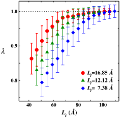
The lower panel of Fig. 1 shows the time-averaged cross section for a (40,0) CNT filled with 16.85 liquid for a few selected . With decreasing , the shape of the cross section changes from a circle to an ellipse. Fig. 2 shows the evolution of vs the length of the CNT () for a (40,0) tube, where the different symbols denote systems with different lengths of liquid. We find that the order parameter can clearly distinguish the CNT shape change from circle to ellipse. From Fig. 2, one can see that, for longer , remains at an average value of one (corresponding to a circular shape) within the error bars, while deviates from one for shorter . The critical length can be located from this figure. It should be pointed out that the critical length is not dependent on the specific definition of order parameter. Another order parameter based on the Fourier spectrum of a shape fluctuation function Khare96 ; Schlober99 was also tested and the results do not show significant differences. For all studied samples, when is smaller than a certain critical length, the shape of the cross section will change from circle to ellipse. The shape changes are purely elastic deformations and the system can relax reversibly by removing the liquid.
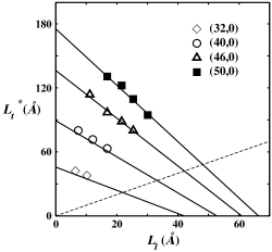
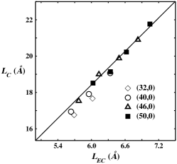
Fig. 3 shows the critical length of the tube vs the liquid length for all CNTs studied, where the solid line is plotted based on Eq. 5 using the parameter values given above. One can see that the MD results are in excellent agreement with the theoretical predictions. The MD results are consistent with a linear relationship between and as expected from the model analysis (see Fig. 4). A best fit produces a slope of 3.0340.014, which is in excellent agreement with the theoretical prediction of .
The critical length (Eq. 5) affords a few potential applications in nano-science or in designing nano-devices. One possible application is the measurement of the elastic bending stiffness () of the tube or the contact angle. For this purpose, we only need knowledge of as a function of by filling liquid into the tubes. If the and contact angle are known, can be obtained. On the other hand, if is known, the contact angle can be estimated. The capillary induced structural transformation also provides an ideal mechanism of conversion of capillary energy to elastic energy. If the values of the interface energies in Eq. 5 are sensitive to the temperature, or to other environment variables, an environment-controlled nano-machine could be achieved.
In summary, the capillary-induced instability of elastic circular tubes has been studied by combining theoretical analysis and MD simulation. The instability depends on two key length-scales, the elasto-capillary length which represents the typical radius of curvature produced by capillary forces on an elastic tube and the characteristic geometric length , which defines a typical reduced size of the tube. At the critical point, is found to be proportional to , above which a tube preserves a circular shape. The MD results are found to be in excellent agreement with the theoretical prediction. The current results can be useful to the design of nano-devices.
Acknowledgements.
We thank Prof. B. B. Laird for his helpful discussion. This research is supported by the National Science Foundation of China, the special funds for major state basic research and CAS projects.References
- (1) P.-G. de Gennes, F. Brochard-Wyard, and D. Quere, Capillarity and Wetting Phenomena: Drops, Bubbles, Pearls, Waves (Springer, New York, 2003)
- (2) J. Bico, B. Roman, L. Moulin, and A. Boudaoud, Nature 432, 690 (2004)
- (3) H.-Y. Kim and L. Mahadevan, J. Fluid Mech. 548, 141 (2006)
- (4) D. L. Hu and J. W. M. Bush, Nature 437, 733 (2005)
- (5) M. Heil, A. L. Hazel, and J. A. Smith, Respir. Physiol. Neurbiol. 163, 214 (2008)
- (6) A. E. Cohen and L. Mahadevan, Proc. Natl. Acad. Sci. 100, 12141 (2003)
- (7) C. Py, P. Reverdy, L. Doppler, J. Bico, B. Roman, and C. N. Baroud, Phys. Rev. Lett. 98, 156103 (2007)
- (8) J. Huang, M. Juszkiewicz, W. H. de Jeu, E. Cerda, T. Emrick, N. Menon, and T. P. Russell, Science 317, 650 (2007)
- (9) S. Neukirch, B. Roman, B. de Gaudemaris, and J. Bico, J. Mech. Phys. Solids 55, 1212 (2007)
- (10) N. Chakrapani, B. Wei, A. Carrillo, P. M. Ajayan, and R. S. Kane, Proc. Natl. Acad. Sci. 101, 4009 (2004)
- (11) B. Pokroy, S. H. Kang, L. Mahadevan, and J. Aizenberg, Science 323, 237 (2009)
- (12) L. D. Landau and E. M. Lifshitz, Elasticity Theory (Pergamon, Oxford, 1996)
- (13) S. Timoshenko and J. Gore, Theory of Elastic Statility (McGraw-Hill, New York, 1988)
- (14) L. Boruvka and A. W. Neumann, J. Chem. Phys. 66, 5464 (1977)
- (15) D. Y. Sun, D. J. Shu, M. Ji, F. Liu, M. Wang, and X. G. Gong, Phys. Rev. B 70, 165417 (Oct 2004)
- (16) Y. Yang and D. Y. Sun, To be published
- (17) S. J. Plimpton, J. Comput. Phys. 117, 1 (1995)
- (18) D. W. Brenner, O. A. Shenderova, J. A. Harrison, S. J. Stuart, B. Ni, and S. B. Sinnott, J. Phys.: Condens. Matter 14, 783 (2002)
- (19) M. I. Mendelev, S. Han, D. J. Srolovitz, G. J. Ackland, D. Y. Sun, and M. Asta, Philos. Mag. 83, 3977 (2003)
- (20) J. Broughton and G. Gilmer, Acta Metall. 31, 845 (1983)
- (21) R. L. Davidchack and B. B. Laird, J. Chem. Phys. 118, 7651 (2003)
- (22) E. Durgun, S. Dag, V. M. K. Bagci, O. Gülseren, T. Yildirim, and S. Ciraci, Phys. Rev. B 67, 201401 (May 2003)
- (23) F. Ding, K. Bolton, and A. Rosen, J. Phys. Chem. B 108, 17369 (2004)
- (24) D. Wei, L. Cao, L. Fu, X. Li, Y. Wang, G. Yu, and Y. Liu, Adv. Mater. 19, 386 (2007)
- (25) M. J. P. Nijmeijer, A. F. Bakker, C. Bruin, and J. H. Sikkenk, J. Chem. Phys. 89, 3789 (1988)
- (26) S. W. Sides, G. S. Grest, and M.-D. Lacasse, Phys. Rev. E 60, 6708 (Dec 1999)
- (27) A. Kutana and K. P. Giapis, Phys. Rev. B 76, 195444 (2007)
- (28) T. Werder, J. H. Walther, R. L. Jaffe, T. Halicioglu, and P. Koumoutsakos, J. Phys. Chem. B 107, 1345 (2003)
- (29) Q. Lu, M. Arroyo, and R. Huang, J. Phys. D: Appl. Phys. 42, 102002 (2009)
- (30) S. V. Khare and T. L. Einstein, Phys. Rev. B 54, 11752 (Oct 1996)
- (31) D. C. Schlößer, L. K. Verheij, G. Rosenfeld, and G. Comsa, Phys. Rev. Lett. 82, 3843 (May 1999)