Collective dynamics of excitons and polaritons in semiconductor nanostructures
Abstract
Time resolved photoluminescence is a powerful technique to study the collective dynamics of excitons and polaritons in semiconductor nanostructures. We present a two excitation pulses technique to induce the ultrafast and controlled quenching of the exciton emission in a quantum well. The depth of the dip is given by the magnitude of the warming of the carriers induced by the arrival of a laser pulse when an exciton population is already present in the sample. We use this technique to study the relaxation mechanisms of polaritons in semiconductor microcavities, which are of great importance to enhance the conditions for their condensation under non-resonant excitation. We also explore the dynamics of polariton fluids resonantly created in the lower polariton branch in a triggered optical parametric oscillator configuration, showing evidence of polariton superfluidity, and opening up the way to the real-time study of quantum fluids.
1 Introduction
Semiconductor nanostructures offer a privileged workbench for the study of many fundamental properties of the light-matter interaction and of the collective excitations in solids. Due to single atomic monolayer resolution achieved with epitaxial growth techniques, semiconductor devices can be designed into heterostructures in which the dimensionality of the excitations, the strength of the light-matter interaction and the particle character according to its statistics (bosonic or fermionic) can be finely controlled. Additionally, if the materials of choice in the structure present a direct gap, excitations in its basic form of electrons promoted from the valence to the conduction band can be easily created and detected by optical means.
In quantum wells (QWs), optical excitation leads to the formation of two types of populations: free electrons and holes, and exciton complexes. The two types of populations coexist in quasi thermal equilibrium [Szczytko2004, Chatterjee2004, Bajoni2006b], with a temperature which decreases in time towards the lattice temperature when the excitation is pulsed [vonderLinde1979, Capizzi1984, Leo1988, Yoon1996, Bajoni2006b]. By varying the lattice temperature and density of the photoexcited carriers it is possible to control the ratio between the two populations, allowing for the observation of a transition from an exciton dominated phase (insulating due to the neutral character of these quasiparticles) to a free carrier phase (i. e. conducting) [Kaindl2003, Kappei2005, Amo2006, Stern2008]. Additionally, the energy separation of the exciton and free carrier recombination enables the detailed study of phase-space filling effects associated to the fermionic character of the free electron-hole populations [Kappei2005]. For instance, Pauli blockade is one of the typical effects in a fermionic degenerate system [Warburton1997, Kalevich2001, Ono2002], and has been shown to greatly alter the electron spin-flip dynamics in semiconductors and, consequently, the polarisation dynamics of the light emitted by the system [Potemski1999, Dzhioev2002, Nemec2005, Amo2007b].
Semiconductor nanostructures allow also for the study of the many body properties of boson ensembles. In particular, microcavities consitute an excellent playground. In these systems the fundamental excitations are polaritons: bosons formed from the linear combination of quantum well excitons embedded in a cavity, and the photon modes confined by Bragg mirrors. Due to their partially photonic nature, polaritons have a very small mass, (, the free electron mass) and, consequently, a very high critical temperature for Bose-Einstein condensation (BEC) [Kasprzak2006, Christopoulos2007, Christmann2008]. Additionally, the properties of the ensemble can be easily probed through the light escaping from the cavity, which arises from the annihilation of polaritons and contains all the energy, coherence and density information of the polariton ensemble inside the cavity. Recent experiments have shown the achievement of polariton condensates in CdTe and GaAs based microcavities at temperatures of the order of 10 K [Kasprzak2006, Balili2007, Wertz2009]. Despite their out of equilibrium character (their lifetimes range up to 10 ps) polaritons have shown similar phenomenology to that observed in atomic condensates. The spontaneous [Lagoudakis2008] and imprinted [Sanvitto2009] appearance of quantized vortices, long-range order [Lai2007b] or Bogoliubov like spectra of excitations [Utsunomiya2008] are among some of the phenomena associated to a condensate of interacting bosons that have been reported in the microcavity system. However, the observation of this phenomenology in a semiconductor microcavity does not depart significantly from what can be observed in purely photonic systems, such as in vertical cavity surface emitting lasers [Scheuer1999, Bajoni2007]. A milestone in the study of the macroscopic quantum character of interacting boson systems in semiconductors would be the observation of superfluidity, understood in its most general sense: the absence of friction of a particle ensemble when traversing an obstacle [Amo2009, Amo2008].
In this tutorial we present several optical approaches to manipulate the distribution of excited particles in two types of semiconductor nanostructures. We will do this by using different experimental configurations in an all optical set up. In section 2 we focus on photoexcited electrons in QWs. We will see that the photoluminescence spectra are characterized by exciton and free electron-hole recombination. Free carriers in the density regime under study can be well described by a Boltzmann distribution whose temperature can be extracted from the spectral characteristics of the free electron-hole recombination. We will show, that the temperature of pre-phototexcited carriers can be altered in the picosecond timescale by the arrival of a short pulse. The induced ultrafast warming of the electron populations results in an abrupt switch-off of the exciton emission.
In sections 3 and 4 we concentrate on a bosonic system: polaritons in semiconductor microcavities. Contrary to electrons, bosons can macroscopically condense in a quantum state, at sufficiently low temperatures. The most extended configuration employed in microcavities to explore this phenomenon is the use of the energy trap in momentum space found in the lower polariton branch dispersion around . Under non-resonant excitation, polaritons are formed in the reservoir at high momenta, outside the trap. During their relaxation towards lower energy states, due to their particular dispersion which prevents the efficient relaxation of energy and momentum, polaritons tend to accumulate just outside the trap in the so called bottleneck region [Tartakovskii2000, Senellart2000].
Relaxation from the bottleneck region to the bottom of the polariton trap is a slow process at low excitation densities, as it requires the simultaneous relaxation of significant amounts of energy and momentum [Malpuech2002]. This so-called bottleneck effect has prevented the observation of polariton condensation in GaAs based microcavities until very recently [Balili2007, Wertz2009]. In section 3 we will show experimental results on the transition from incoherent polariton emission to photon lasing when increasing the excitation density in a GaAs based microcavity, as a consequence of the bottleneck effect. Additionally, we will show results on the ultrafast modification of the distribution of polaritons in the bottleneck under two pulses photoexcitation, similar to the configuration presented in section 2 for QWs. These experiments demonstrate that the ultrafast warming of polariton gases is possible, with potential applications on the study of the polariton condensation and on the overcoming of the bottleneck problem in the polariton relaxation [Tartakovskii2000, Krizhanovskii2004, Perrin2005].
Finally, in section 4 we address the dynamic properties of polariton condensates resonantly created on the lower polariton branch. Using a novel excitation configuration based on the optical parametric oscillator, we can create polariton wavepackets with a precise non-zero momentum and a lifetime three orders of magnitude larger than that of polaritons [Amo2009]. Additionally, by use of a time-resolved high-resolution imaging set-up, we can follow the real- and momentum-space time evolution of the polariton wavepackets. We observe a strong linearization of the dispersion and we find evidence of superfluid behaviour of polaritons. The introduced experimental configuration opens up the way to the study of a variety of collective effects, like the formation of solitons or vortices, and the study of non-spontaneous phase transitions.
2 Ultrafast warming of carriers in QWs
Our first approach to the ultrafast optical manipulation of carrier distributions will be developed in semiconductor QWs. After a pulsed photoexcitation of a QW, the photoluminescence (PL) dynamics are dominated by the exciton emission. The time evolution of the emitted intensity is determined by the interplay of exciton formation dynamics, its recombination time and by the thermalization and cooling of the free electrons and holes from which the exciton populations are fed [Kaindl2003, Szczytko2004, Chatterjee2004, Amo2006]. Once free carriers have thermalized after the first few hundreds of femtoseconds [Rota1993b, Alexandrou1995], the strong Coulomb-dipole interaction forces the exciton population to stay in thermal quasiequilibrium with the bath of electrons and holes [Szczytko2005, Bajoni2006b]. This means that the temperature and, therefore, momentum distribution of both species, are the same at all times. As the exciton PL arises just from states with almost no in-plane momentum () due to momentum conservation constraints during the recombination process, any change of temperature in the exciton population will be manifested in the exciton emission. In this section we present experimental results on the optical manipulation of a photogenerated exciton population in QWs, by applying a delayed, non-resonant optical pulse. This pulse abruptly warms an already-thermalized free electron-hole plasma in the QW which, consequently, causes a sudden warming of the exciton populations. The direct consequence of the abrupt heating of the exciton distribution is the appearance of a sharp dip in PL emission when the delayed pulse reaches the sample [Amo2008b].
2.1 Photoluminescence under two pulses excitation
The studies have been carried out on two samples based on GaAs/AlAs: the first one was a heterostructure with a single wide QW (20 nm) grown at Laboratoire de Photonique et de Nanostructures in France, the second one contains multiple (50) narrow QWs (7.7 nm), grown at the Paul Drude Institute in Germany. Similar results were also found in a multiple InGaAs/GaAs QW sample (10 nm), grown at the University of Sheffield, evidencing the generality of the phenomena presented in this section. In all cases the samples were kept in a cold finger cryostat at 9 K. We employed the time resolved PL excitation and detection configurations in a back reflection geometry depicted in figure 1 (a). Excitation was performed with a Ti:Al2O3 laser that produced 1.5 ps long pulses with energy 26 meV above the heavy-hole (hh) exciton. We use two consecutive pulses ( and ), whose power and delay can be independently controlled by means of attenuators and a delay unit. Both pulses arrive at the sample at the same excitation spot (20 m in diameter). The PL from the excitons and the electron-hole recombination is collected by a streak camera attached to a spectrometer,with an overall time and energy resolution of 15 ps and 0.2 meV, respectively
Figure 1 (b) and (c) show streak camera images of the excitonic emission from the single QW sample after excitation by one single pulse of 70 W and by two identical consecutive pulses delayed by 400 ps (70 W each), respectively. In the latter case, a clear dip appears in the emission of the hh exciton (black arrow) at the time of arrival of (white arrow).
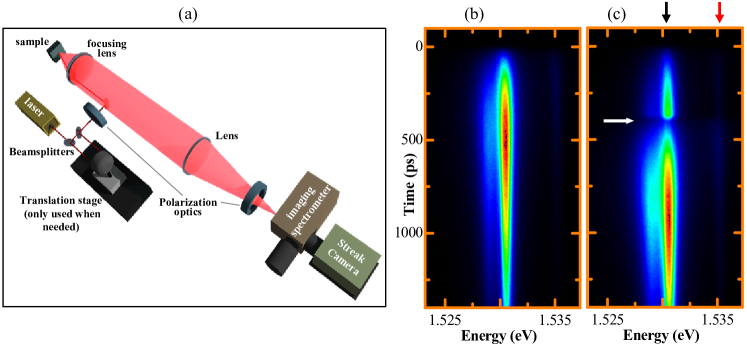
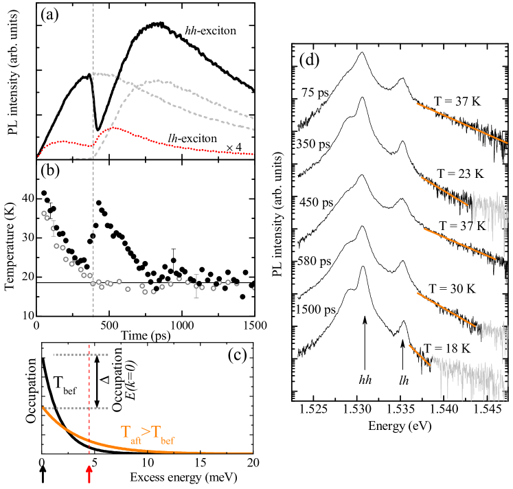
Figure 2 (a) shows in detail the time evolution of the hh exciton PL when the two pulses excite the QW independently (dashed lines) and when both excite it jointly (solid line). The emission from the light-hole (lh) exciton can also be detected 4.7 meV above the hh exciton (red dotted line; red arrow in figure 1). In contrast to the hh, the lh dynamics do not show the appearance of a dip in the PL at the time of arrival of .
2.2 Origin of the dip: thermodynamical model
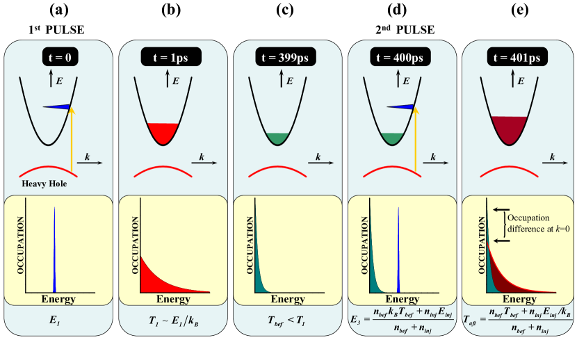
The origin of the dip can be explained considering the redistribution of carriers in the bands that takes place after the absorption of . To account quantitatively for the observed magnitude of the dip depth, we have developed a dynamical quasi-equilibrium thermodynamical model of the carriers in the QW [Amo2008b], which is sketched in figure 3. The absorption of the first non-resonant pulse creates a non-thermal population of electrons and holes at high energies in the conduction and valence bands [figure 3 (a)]. In a time scale of the order of 200 fs the carriers distribute in the bands achieving a well defined temperature, higher than the lattice temperature [panel (b)] [Knox1992, Rota1993b]. The carrier densities considered in this section are far from the degeneration limit, and the electron population can be well described by a Maxwell-Boltzmann distribution function:
| (1) |
where is Boltzmann’s constant, is the carrier’s density of states, is the energy of the electrons above the bottom of the conduction band, and and are their density and temperature, respectively. A similar description can also be made for holes. As time evolves, the carrier distributions cool down due to the interaction with phonons, and the populations decrease due to pair recombination and exciton formation [panel (c)] [Leo1988b]. When reaches the QW new hot carriers are photoinjected () at high energy in the bands [, panel (d)]. Due to efficient carrier-carrier scattering, the newly created carriers and the pre-existing populations rethermalize in a timescale given by the pulse duration, to a temperature () higher than the carrier temperature right before the absorption of () [panel (e)]. Thus, the effect of the delayed pulse is to warm-up the carriers and increase their concentration, in a time-scale shorter than a few picoseconds (2 ps).
Simultaneously to the thermalization and cooling processes we have just described for the free carriers, electrons and holes bind to form excitons in a time-scale of the order of several hundreds of picoseconds, for the excitation densities and lattice temperature of our experiments [Szczytko2004, Bajoni2006b]. As discussed above, the exciton population obeys also a Maxwell-Boltzmann distribution law. Recent studies have successfully developed kinetic theories, fitted to experimental data, based on the assumption that excitons and the coexisting electron-hole plasma have the same temperature at all times [Szczytko2004, Chatterjee2004, Szczytko2005, Hoyer2005]. Bajoni et al. [Bajoni2006b] have actually measured independently the temperature of the excitons and that of the electron-hole plasma, in a sample similar to the single, wide QW structure used here. They observe that both species do show the same temperature for times larger than 200 ps after a pulsed non-resonant excitation. For shorter times their temperatures differ and Bajoni and coworkers propose that the exciton populations have not reached a thermal distribution, while the electon-hole plasma has thermalised in less than one picosecond. This argument agrees with the theoretical predictions of Selbmann et al. in [Selbmann1996], where they discuss that the exciton formation is favored for electrons lying with kinetic energies around the LO-phonon, as LO-phonon assisted electron-hole binding is the most favorable exciton formation mechanism. This fact, added to the slow exciton momentum relaxation, would result in the non-thermalicity of the exciton population in the first 200 ps. During this initial time excitons are simultaneously forming, relaxing and thermalizing.
The situation in our two-pulses configuration is slightly different. In our case reaches the sample more than 200 ps after the arrival of , and we can expect thermal equilibrium between excitons and plasma at that time. Therefore, injects hot electron-hole pairs in a system populated by already thermalized excitons. In the first picoseconds, after the arrival of , the rethermalized electron-hole plasma just warms the preexisting excitons. However, in contrast to the plasma population, due to the slow formation dynamics of excitons —two orders of magnitude slower than the excitation pulse—, the exciton density is hardly altered within the pulse duration. Thus, no additional non-thermalized excitons should be considered during the time of arrival of .
Following this argument, we can assume that excitons and the electron-hole plasma have the same temperature at the time of arrival of , and probably for some time after that. Therefore, an analogous dynamics to that of the free carriers takes place also for the exciton population: during the arrival of , the abrupt warming of the carriers results in an ultrafast warming of the exciton population.
With these assumptions and using equation (1) the appearance of the dip in the hh-exciton PL can be understood. The hh-exciton occupation of the zero momentum states () before/after the arrival of is given by:
| (2) |
where is the pre-existing density of excitons at the arrival time of the pulse, is the excitonic density of states, and is the exciton temperature (equal to that of carriers) before/after the arrival of .
The PL intensity of the hh excitons is directly proportional to the occupation of states with close to zero, as these are the excitonic states that can couple to light. Therefore, modifications in the occupation of these states at the arrival of the delayed pulse [see figure 2 (c)] induce changes in the PL. In particular, the abrupt warming of the carriers produced by the arrival of () results in an abrupt drop of the populations () and consequently in an ultrafast quenching of the hh-PL, as born out by our experiments (see figure 2).
The details of the exciton redistributions after the arrival of also accounts for the absence of a dip in the lh emission. The lh-exciton energy is higher than that of the hh exciton and the increase in temperature of the excitons results in a negligible change of the excitonic occupation at the lh states [as depicted in figure 2 (c) for an energy marked with the red arrow].
We can gain insight into the quantitative validity of this quasi-equilibrium thermodynamical model, by directly measuring the carrier temperature in the single, wide QW. Figure 2 (d) shows PL spectra detected at different times after the arrival of ( arrives at a delay of 400 ps). The spectra show the hh- and lh-exciton lines as well as the direct free electron-hole pair recombination above the lh-exciton energy. A Maxwellian fit can be performed at the high energy tail (indicated by solid lines) to extract the carrier temperature. Figure 2 (b) shows the temperatures of the electron-hole plasma for the conditions of figure 2 (a). The solid (open) dots corresponds to the double (single) pulse experiments. In the case of the single pulse excitation, a monotonous cooling of the plasma is observed, with a final equilibrium temperature (19 K) higher than the lattice temperature (9 K) [Leo1988b, Yoon1996]. In the two-pulses experiment, an abrupt warming of the plasma, and consequently of the excitons, can be observed at the time of arrival of . At longer times ( ns) the same temperature as that obtained in a single pulse experiment is reached.
The measured temperature of the carriers enables us to predict the dip depth following our model. A relative dip depth can be defined as , where () is the intensity of the hh-exciton PL right before (after) the arrival of . From this definition and equation (2), the relative dip depth can be related to the excitonic temperature before and after the arrival of by:
| (3) |
The inset of figure 4 (a) shows in solid dots () the values of directly measured from the hh-exciton PL as a function of the delay between the two pulses for the single QW. The high values of demonstrate the capability of to quench the PL. The open dots () depict obtained from the measured carrier temperature ratio and equation (3). In a symmetrical manner, figure 4 (a) depicts in open dots as directly measured, while the solid points compile the temperature ratio as obtained from the observed dip depth and equation (3). Figure 4 (b) shows as a function of the power of relative to that of . In this case, the signal to noise ratio of the spectra limited the lowest power of for which the temperature of the electron-hole plasma could be extracted. The good agreement between the temperature ratios obtained from the relative dip depth in the hh PL () and those measured directly () confirms the validity of our model.
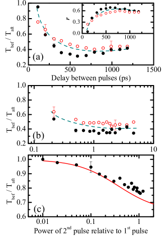
This is further demonstrated in figure 4 (c) that depicts obtained from the hh-exciton PL for the GaAs/AlAs narrow multiple QW sample as a function of the power of (delay = 300 ps) in the low power regime (solid points). In this case the broader excitonic linewidth hinders the possibility of extracting the carrier temperature from the spectra. Nonetheless, our model reproduces quantitatively the observed experimental dependence without the need of any adjustable parameters, as shown by the red line, which plots obtained in the following way: the temperature after is given by , where is the density of carriers at the time of arrival of , determined from the power of and the PL decay-time; is the density photoinjected by ; and , taken as 38 K and 24 K, respectively, are the initial carrier temperature and that measured at a delay of 300 ps in the single QW experiments (see figure 2), which were performed under very similar conditions to those in the multiple-QW structure.
The experiments and model presented in this section demonstrate that ultrafast optical control of the off-transients in QWs is possible. Additionally, although the results presented here concentrate on the light emission from this kind of nanostructure, the physics and observed phenomena can be directly extrapolated to more complicated systems such as semiconductor microcavities, vertical cavity surface emitting lasers (VCSELs) or structures with active media of higher dimensionality, like bulk direct-gap semiconductors. In particular, the relationship between the dip depth and the carrier warming can be exploited to study the carrier-relaxation dynamics in microcavities as we will show in section 3.
3 Relaxation of microcavity polaritons
Very interesting particles intimately related to the QW excitons are microcavity polaritons. These objects arise from the strong coupling between an exciton resonance and a photon mode confined in a two dimensional optical cavity. Morphologically, the optical cavity is conformed by a two-dimensional high finesse Fabry-Perot resonator composed of an upper and a lower Bragg reflector separated by a cavity spacer with a thickness times the wavelength of the optical mode to be confined, with being an integer number. The Bragg reflectors are composed of alternating layers of two semiconductor materials with different refractive index with an optical length of . Typically, when the number of layers in each reflector is on the order of 25, reflectivities as high as 99.95% can be achieved in GaAs based systems, giving rise to a confined photonic mode with a spectral width on the order of 0.1 meV.
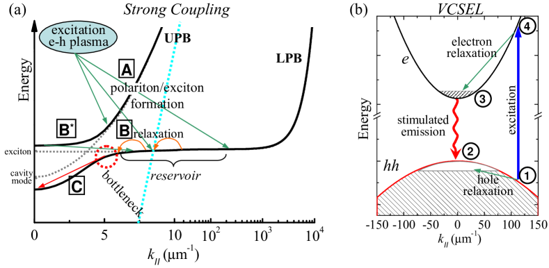
In the cavity spacer, where the confined electromagnetic field has its maxima, a single or a group of identical QWs is grown. The thickness of the spacer is designed so that the energy of the confined photon mode is equal or close to that of the QW exciton. Under these conditions, strong coupling between the photon and exciton modes can be achieved [Weisbuch1992], giving rise to polaritons, the new eigenstates of the system which are a quantum mixture of exciton and photons. One of their most interesting characteristics is their rich dispersion, composed of two branches, the upper and lower polariton branch (UPB and LPB, respectively), which are shown in figure 5 (a).
3.1 Polariton condensates
Due to their partially photonic character, polaritons in the momentum trap around have a very small mass, on the order of times the free electron mass. This characteristic added to the fact that polaritons are composite bosons have converted microcavities in an ideal system for the study of bosonic quantum degeneracy at temperatures ranging from a few kelvins to room temperature [Kavokin2007]. Among other observations, polaritons have evidenced lasing without inversion [Imamoglu1996, Dang1998, Christopoulos2007, Christmann2008, Bajoni2008], Bose-Einstein condensation [Kasprzak2006, Balili2007], long range order [Kasprzak2006, Lai2007b], appearance of quantized vortices [Lagoudakis2008, Sanvitto2009] and superfluidity [Amo2009, Amo2008], as well as phenomena like optical parametric oscillation (OPO) [Stevenson2000, Romanelli2007] and amplification [Savvidis2000, Sanvitto2005b], optical bistability [Baas2004, Demenev2008] and squeezing [Karr2004]. Many of these behaviours show particularities absent in other bosonic systems (like ultracold atomic condensates) due to the short polariton lifetime ( 10 ps). For instance, the steady state of the system is given by the interplay between pumping, relaxation and decay, and not by a thermodynamic equilibrium. Additionally, very rich spin physics are found in these systems, which can be directly accessed via the polarization control of the excitation and detected fields [Martin2007b, Shelykh2010].
Several terms like condensate, polariton laser and Bose-Einstein condensate, are used in the literature to refer to related but subtly different phenomena with respect to the coherent phases of polaritons in semiconductor microcavities. For the sake of clarity and to avoid ambiguities in the present manuscript, we would like to briefly address the meaning of these three concepts.
Condensate is the most general of the three, and it is employed to designate a macroscopic ensemble of particles occupying the same quantum state. In this sense, no matter how we excite the system (on-resonance or out-of-resonance), a gas of polaritons in a state which has an occupation above 1, is a condensate [Keeling2007].
Bose-Einstein condensation makes reference to the creation of a condensate which is in thermodynamic equilibrium, i. e. with a well defined temperature and chemical potential. BEC cannot take place in a purely bi-dimensional system at finite temperatures. For this reason this term may only be employed for polaritons under very special circumstances, in particular when condensation takes place under non-resonant excitation, at positive detunings (to allow for the polariton gas to thermalize, as we will discuss below) [Deng2006, Kasprzak2008b, Marchetti2008], and in the presence of an additional confinement [Malpuech2003, Keeling2004b, Kasprzak2006, Balili2007, Malpuech2007]. In a purely two-dimensional system, a Berezinski-Kosterlitz-Thouless (BKT) transition can take place at finite temperatures, with subtle differences with respect to BEC (for instance, in the decay of the spatial coherence with distance) [Pitaevskii2003].
Polariton lasing is employed when the polariton condensate is in a non-thermal state, that is, if a state with occupation above 1 is attained but the total ensemble of polaritons does not follow a thermal distribution [Malpuech2002, Szymanska2006, Christmann2008, Bajoni2008]. Let us note that though in polariton lasers the system is out of thermal equilibrium, much of the physics expected in a system in equilibrium can still be observed due to the extension of the coherence time, which becomes longer than the typical interaction times. This extension arises from the stimulated relaxation processes from reservoir states to the macroscopically occupied condensed state [Love2008]. Finally, a related term is photon lasing, which is observed in microcavities if coherent emission under out-of-resonance excitation takes place in the weak coupling regime, as in a VCSEL (see discussion below) [Butte2002a, Bloch2002, Szymanska2002, Bajoni2007, Bilykh2009].
The experiments showing so far polariton condensation under out-of-resonance excitation can be ascribed to either BEC or polariton lasing depending if the gas can be described by a thermalized distribution or not, while the BKT transition has not yet been clearly demonstrated experimentally. In planar microcavities, polariton BEC has been claimed either in artificial [Balili2007] or natural traps formed during the growth process [Kasprzak2006, Sanvitto2009b, Krizhanovskii2009], breaking the translational symmetry in the plane of the cavity and allowing for the spontaneous condensation at finite temperatures. However, it must be noted that the experimental determination of the thermal character of the gas is not always unambiguous [Bajoni2007, Nelsen2009].
In the following sections we will mainly refer to the general concept of condensate, particularly in section 4, where we describe experiments under resonant excitation. The high occupation of the addressed state is induced by the direct injection of polaritons via the excitation laser, and the gas does not present a thermal character.
3.2 The bottleneck effect
The most extended configuration employed to explore the phenomenon of spontaneous polariton condensation is the use of the energy trap in momentum space present in the lower polariton branch around under non-resonant excitation. If a sufficient amount of polaritons accumulate in the quantum states at the bottom of the trap, condensation takes place. In order to wash out the coherence of the excitation source (a laser) and to be able to observe the spontaneous formation of a condensed phase, non-resonant optical excitation is required, expecting that relaxation in the bands will destroy any trace of the initial coherence of the injected carriers. As depicted in figure 5 (a) the non-resonantly created polaritons relax energy and momentum until they reach the momentum-bottleneck region.
Relaxation from the bottleneck region to the bottom of the polariton trap is a slow process at low excitation densities, as it requires the simultaneous relaxation of significant amounts of energy and momentum. LO-phonon assisted scattering cannot participate due to energy conservation constraints, and only polariton-polariton [Tartakovskii2000, Senellart2000] and acoustic phonon-polariton interaction can mediate in the polariton relaxation [Malpuech2003]. The presence of an electron gas can also enhance the relaxation process [Malpuech2002b, Tartakovskii2003, Lagoudakis2003, Perrin2005b, Bajoni2006].
Apart from the relaxation bottleneck, another important constraint for the accumulation of polaritons at the bottom of the trap is their reduced lifetime. Due to their photonic content, their lifetime is of the order of 1-10 ps in standard GaAs and CdTe based systems. Faster relaxation times are required to achieve occupations at above 1 to trigger the condensation. The usual strategy has been to increase the excitation density until the occupation of the ground state is high enough, as long as the strong-coupling regime is not destroyed by the high carrier density (due to exciton ionization [Bloch2002]).
This situation is achieved at low temperatures (5 K) in CdTe based microcavities [Richard2005, Kasprzak2006] and in GaN based systems at room temperature [Christopoulos2007, Christmann2008, Baumberg2008], where the exciton binding energy is very high (around 25 meV in the former case, and 40 meV in the latter one). In the case of GaAs based microcavities, particularly relevant due to their high crystalline quality, the reduced exciton binding energy (around 10 meV) has not allowed, until recently, the observation of polariton condensation under non-resonant excitation: screening from the non-resonant injected carriers ionizes the polaritons at densities lower than those required to produce the condensation in the bottom of the trap. When polaritons ionize, the strong coupling is lost and the microcavity starts to behave as a VCSEL, with laser emission from the cavity mode [Bajoni2007]. A strategy to circumvent these difficulties has been the creation of a confining real space trap where polaritons condense far from the excitation point [Balili2007]. Recently, an improved microcavity design with an enhanced Rabi splitting has allowed the observation of condensation at excitation densities below those driving the system into weak coupling [Wertz2009].
In this section we will study the transition from the strong to the weak coupling regimes, and the onset of photon lasing, in GaAs based microcavities under non-resonant excitation. By making use of a two pulses configuration as that of section 2 and the model given by equation (3) we present a technique which allows the controlled warming of reservoir polaritons, simultaneously providing insights on the relaxation mechanisms from the upper to the lower polariton branches.
3.3 Polariton formation and relaxation
The studied sample is a GaAs microcavity with two stacks of three In0.06Ga0.94As QWs, with a Rabi splitting of 6 meV, which was kept at 5 K. The sample was designed and grown at the University of Sheffield. The wedged shape of the cavity spacer allows for the study of different exciton-cavity detunings [, where is the cavity (exciton) energy] just by choosing different positions on the sample. Single pulse excitation (1.5 ps long, at a repetition rate of 82 MHz) was performed at an energy of 1.63 eV, above the first reflectivity minimum of the stop band, in the continuum of electron-hole states of the GaAs cavity spacer, except in section 3.5 where, in some of the presented experiments, the excitation is resonant with the UPB close to its minimum. The excitation spot on the sample is kept at around 100 m in diameter. The PL was energy and time resolved in a configuration analogous to that depicted in figure 1. The emission from the states was selected by means of a pinhole in the far field.
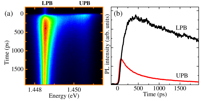
Figure 6 (a) shows a streak-camera image of the emission at meV after non-resonant excitation for low laser power (4 mW). Under these conditions the LPB and UPB modes can be observed. In figure 6 (b) the time evolution traces of the upper and lower polaritons are shown. The lower polariton branch presents slow dynamics, characterized by a long rise and decay. In the case of the upper polaritons, the dynamics are much faster.
The time evolution characteristics can be qualitatively understood considering the phenomenological model described in figure 5 (a). Free electron-hole pairs are created by the non-resonant pulses in the QWs. Analogously to the process described in section 2.2, in less than a picosecond the electrons and holes achieve thermalized distributions. Simultaneously, polaritons start their formation process {[A] in figure 5 (a)}, populating both the UPB and the LPB. The cavity lifetime in the samples under study is of the order of 2 ps. For states close to , where polaritons have an important photonic component () this implies that the polariton lifetime is on the order of 4 ps. For this reason, any polariton falling inside the dispersion energy trap escapes very fast from the system. On the other hand, polaritons above the bottleneck, outside the trap, possess a very high excitonic component () and a weak coupling to light. Additionally, above a certain momentum, excitons lie outside the light cone [indicated by a blue dahsed line in figure 5 (a)] and do not couple to light at all.
Thus, the polariton lifetime is very different depending strongly on the polariton momentum. Inside the trap the polariton modes are strongly depleted, while above the bottleneck polaritons have long lifetimes and dynamics similar to that of excitons, due to their high excitonic component. Moreover, the bottleneck effect results in very slow relaxations from the reservoir to the bottom of the trap {[C] in figure 5(a)}. Given the very different lifetimes of polaritons inside and outside the trap, and the bottleneck effect, it is straightforward to see that any polariton relaxing from the reservoir to the trap immediately escapes from the system. The emission dynamics at , for non-resonant excitation, is mainly determined by the polariton dynamics of the reservoir states close to the bottleneck, as these require the least amount of phonon or carrier scattering events to relax their energy and momentum.
The situation we have just described about the population distribution in the LPB can be extended to any detuning, the only difference being that at very positive detunings the LPB lifetime in the trap is increased, and the bottleneck effect is reduced. Eventually, at very positive detuning, the bare exciton dynamics are recovered. Still, states close to are significantly depleted as compared to the states outside the light cone [Koch2006].
According to the arguments presented in the previous paragraphs, the LPB polariton dynamics under non-resonant excitation reflects the exciton dynamics at the reservoir states. In this sense, the long rise time depicted in figure 6 (b) is caused by the slow exciton formation, while the decay is mainly characterized by the long exciton lifetime. This interpretation is consistent with calculations of the polariton dynamics at different temperatures and detunings [Savona1999].
The UPB dynamics can also be explained attending to the sketch of figure 5 (a). The upper branch polaritons are very fast depleted due to either their high photonic component (positive ) or to their strong interaction and fast relaxation to reservoir lower branch polaritons {[] in figure 5 (a)} [Sermage1996, Bloch1997]. The large upper polariton linewidth is a manifestation of these interactions.
The dynamics of the states of the UPB depicted in figure 6 (b), at a positive detuning on the order of the Rabi splitting ( meV), is a manifestation of the two above mentioned fast depletion channels. In particular, both the fast rise and the slow decay can be understood as a consequence of the quasi-thermal equilibrium between the reservoir states and the UPB: the fast rise results from the achievement of a polariton distribution in the reservoir, while the decay reflects the cooling of that distribution and that of the total reservoir population itself.
3.4 Transition from the strong to the weak coupling regimes
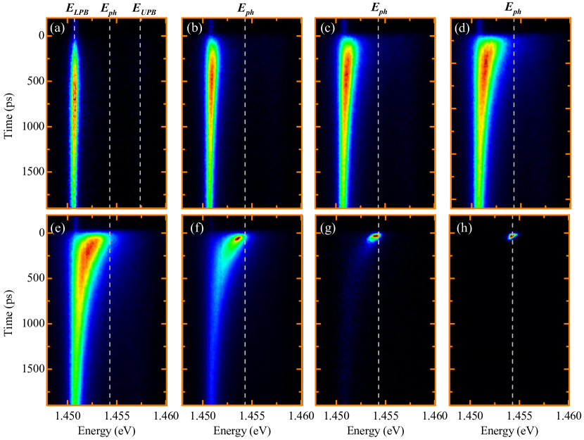
The microcavity PL dynamics dramatically change when the excitation density is varied. This situation is explored in figure 7, where the emission dynamics at is shown as a function of excitation power for a spot of m in diameter, and at detuning very close to zero ( meV). At very low power [figure 7 (a)], a narrow emission ( eV) is observed at the energy of the LPB. Also emission from the UPB can be observed with the appropriate setting of the z-scale, but it is not shown in this figure. As the carrier density is increased [figure 7 (b)-(c)], the polariton linewidth increases due to the enhancement of the polariton-polariton and polariton-carrier interactions [Ciuti1998, Baars2000, Huynh2003]. These interactions are also responsible for the shortening of the rise time as they also reduce the exciton formation time and ease the relaxation to the bottom of the trap. In figures 7 (d)-(f) the transition from the strong- to the weak-coupling is evidenced. At short times, at these powers (and above), the high density of free carriers injected by the non-resonant excitation pulse screens the electrons and holes that form the excitons, leading to their ionization, and the system is driven into the weak-coupling regime, characterized by emission at the energy of the cavity mode (). At longer times, the number of carriers in the system decreases due to recombination. In this way the screening also decreases and the system goes back to the strong-coupling regime, characterized by emission at the energy of the LPB and UPB, as evidenced in figures 7 (d)-(g) at long times.
Once the strong coupling is lost, the dispersion relations of the energy states of the system are given by those of the first electron and heavy-hole subbands, as depicted in figure 5 (b). A four level system can be considered, as indicated in the figure, and population inversion between levels 3 and 2 is easily achieved as the electron and hole relaxation to the bottom/top of their bands is very efficient due to carrier-carrier interaction [Rota1993b]. In this case the Bragg mirrors act as very efficient resonators with a photonic mode very close to the bandgap, and photon lasing is triggered, with a very low power threshold [Pau1996, Butte2002a, Lagoudakis2004].
Figures 7 (f)-(h) show how, as soon as the system reaches the weak-coupling regime, photon stimulated emission takes place and the microcavity is driven into VCSEL operation. Due to the stimulated character of the recombination, the light emission is very fast in this regime. Most available electron-hole pairs at the cavity energy recombine in the first ps.
This situation of photon lasing is very different to that of a polariton BEC or a polariton laser (plaser) [Imamoglu1996]. Optical emission in a plaser or BEC would come from the leakage out of the microcavity of the condensed polaritons at . Due to their bosonic nature, reservoir polaritons with large relax to the condensed state at the bottom of the LPB, via a process of final state stimulated scattering. The condensed polaritons are in a well defined quantum state, and when they leak out of the cavity they present very similar characteristics to those of a conventional photon laser, i.e. monochromaticity, well defined phase, directionality [Bajoni2007]. The fact that the stimulation and emission processes are decoupled can lead, in principle, to plasing devices without excitation threshold [Imamoglu1996].

Figure 7 (f) shows that, at short times after excitation, emission from weakly (at the photon mode) and strongly (at the LPB) coupled modes coexist. This phenomenon can be observed in experiments at very different detunings. Figure 8 shows the emission energy (green and black dots) as well as the intensity (red dots) dependence on pulsed-excitation power at several detunings in the sample. At low excitation density, the microcavity is in the strong-coupling regime with emission occurring at the LPB and UPB energies, with a linear dependence of the photoluminescence intensity on excitation density. The light blue areas depict the transition from the strong to the weak coupling at high densities. Analogously to the analysis carried on figure 7, the transition threshold can be identified by the shift of the emission to the cavity mode states (blue triangles). The appearance of emission at the cavity mode is accompanied by the onset of a superlinear dependence of the photoluminescence intensity on excitation power. Such a superlinear behavior is characteristic of lasing systems right at the threshold density under non-resonant excitation [Sargent1987, Doan2005]. At higher excitation intensities the linear behavior is recovered, as hinted in the lower panel of figure 8.
The width of the light blue areas in figure 8 indicates the excitation power range over which strongly and weakly coupled modes can be observed. At detunings close to zero, where the strongly and weakly coupled modes are furthest apart in energy the coexistence is clearly observed. In this case the coexistence region could probably be extended to higher densities if a larger dynamic range would have been available in these experiments, as the emission from the photon lasing mode increases non-linearly while that of the coupled modes increase linearly with density. Let us also mention that studies in the same system evidence that the coexistence of strong and weak coupling takes place on emission areas smaller than m in diametre [Ballarini2007].
3.5 Polariton relaxation from the UPB in the strong coupling regime
The lower-branch polariton dynamics is mostly determined by the dynamics of the reservoir polaritons, as it was pointed out in the discussion of the polariton relaxation channels [figure 5 (a)] and evidenced by the slow dynamics shown in figure 7 (a). In this section we will gain insight into this relationship through the results of a two pulses experiment analogous to those described in section 2. In those experiments, two delayed excitation pulses and reach the sample on the same excitation spot, inducing an ultrafast warming of the exciton population created by . Figure 9 (a) shows the LPB emission under such a configuration for a spot on the sample at . In this case both pulses excite the sample non-resonantly (above the QW electron-hole continuum) with the same power (0.1 mW) and a delay between them of 450 ps. Analogously to the results presented in section 2, a quench of the photoluminescence is observed at the arrival of the second pulse. creates an electron-hole pair population that decays into reservoir excitons, which eventually relax to the bottom of the polariton dispersion trap giving rise to the early emission shown in figure 9 (a). The arrival of induces an ultrafast warming of the exciton distribution in the reservoir producing an abrupt decrease of the exciton populations at the bottleneck and a subsequent quench of the luminescence.
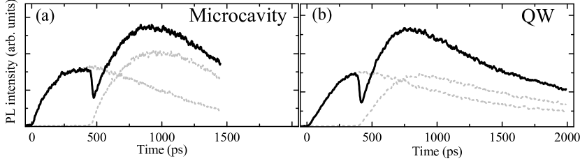
In order to stress that the physics behind the observed dip are fully determined by the redistribution of excitons in the reservoir, we have also performed a similar two pulses experiment in an identical microcavity sample that has been processed (chemical etching) in order to remove the top Bragg mirror. In this way, the luminescence from the bare QWs can be accessed. Figure 9 (b) shows the QW emission under the same non-resonant two pulses experiment (in this case with a delay between pulses of 400 ps). The dynamics of the PL under a single pulse excitation (grey dashed lines) are alike in the microcavity and the QW, evidencing that they have the same origin. For a similar delay between pulses and ratio of the powers of and , the magnitude of the dip is also very similar in both cases, which is what would be expected from the model described in section 2.2 if the dip is caused by the redistribution of polaritons/excitons.
Taking advantage of the model described in section 2.2 and the relation between dip depth and relative temperature change of the excitonic distribution [equation (3)], we are going to study the relaxation of resonantly created upper-branch polaritons. In this case the excitation will no longer be non-resonant above the first minimum of the stop band. Here we will describe two pulses experiments in which polaritons are resonantly injected in an UPB state close to . Figure 10 shows the , LPB emission under excitation with two independent (black lines) and two consecutive (red lines) pulses resonant with the aforementioned UPB state, at different detunings. The delay between the pulses is 285 ps. The first pulse is linearly polarized, the second one is right-circularly polarized, and the left-circular polarized emission is detected. We use this configuration for reasons that will be explained below. Control of the polarization of the excitation and detection paths is performed by use of appropriate combinations of linear polarizers and quarter waveplates.

Let us first concentrate on the dynamics when just one of the pulses, , arrives to the sample (black lines in the lower panels of figure 10). In these experiments , linearly polarized, resonantly injects polaritons at the bottom of the UPB (see figure 10 upper panels). The direct relaxation via phonon emission to the LPB states results in the very fast rise of the PL observed right after the arrival of [Sermage1996]. Nonetheless, a significant portion of polaritons scatter to the reservoir, conforming a thermalized distribution. Some of these polaritons relax, via emission of acoustic phonons, towards , where they escape from the cavity giving rise to the decay observed at later times [Sermage1996, Bloch1997]. When a second delayed pulse reaches the sample, at the same energy and momentum as , the photocreated upper polaritons relax again to the reservoir states with an excess energy given by the difference between the upper polariton energy and the reservoir energy (bare excitonic energy), which is indicated by in figure 10. The second pulse is circularly polarized (injecting spin-up polaritons), while only the circularly polarized emission is detected (from the escape of spin-down polaritons). In this way the direct relaxation of the polaritons injected by from the UPB to the , LPB states is disregarded, as this phonon mediated process does not change the polariton spin. In contrast, the reservoir polaritons do flip their spin via usual exciton spin flip mechanisms [Damen1991, Martin2002b], and any change in their distribution is reflected in the PL emission at . The slow rise observed in the lower panels of figure 10 after the arrival of reflects the time required for reservoir polariton to flip their spin.
The red line in the lower panels of figure 10 shows the LPB emission when the two consecutive pulses reach the sample. In panel (d) a dip in the PL can be observed indicating that the upper polaritons generated by very efficiently relax towards the reservoir states [red arrows in (c)] changing significantly their distribution. By measuring the relative magnitude of the dip depth, and making use of equation (3) we can calculate the temperature increase of the reservoir polaritons induced by the injection of upper branch polaritons by . In the case of [figure 10 (c)-(d)], the temperature increase is given by . For a larger detuning, as that depicted in figure 10 (e)-(f), is significantly increased, and the carriers injected by are at higher temperature and warm stronger the exciton reservoir (), inducing a larger dip. In this case, additionally, the UPB lies within the electron-hole continuum, and injects electron-hole pairs in the system, which warm the reservoir excitons even more efficiently than upper-branch polaritons. Figure 10 (a)-(b) depicts the case of negative detuning. In this case is very small, and the negligible excess energy of the polaritons injected by results in a negligible warming of the reservoir.
These results show that upper branch and reservoir polaritons form part of an ensemble in thermal quasiequilibrium. Even though there is a gap in momentum between the two populations, they strongly interact, making possible the thermal control of one of the two populations by changing the distribution of the other. These properties and the well established relationship between dip depth and temperature change could be an asset to investigate phase transitions, such as condensation of indirect excitons [Butov2002] or polariton BECs [Kasprzak2006], in which the carrier temperature plays an important role.
4 Fluid dynamics of microcavity polaritons
In the previous section we presented experiments under non-resonant excitation in an InGaAs/GaAs/AlGaAs based microcavity. The emission dynamics in the strong-coupling regime are well explained by free carriers and polariton relaxation mechanisms, giving rise to incoherent populations of polariton. Even though only the emission from the states has been so far considered, in this incoherent regime polaritons distribute along the polariton dispersion giving rise to incoherent luminescence from all states within the light cone.
As shown in the experimental results of section 3, under highly non-resonant excitation (via photocreation of free electrons and holes) in the GaAs based studied microcavity it is not possible to reach a quantum condensed phase of polaritons [Bajoni2007]. In CdTe based microcavities a Bose-Einstein condensed state has been observed by Kasprzak and co-workers under such excitation conditions [Kasprzak2006]. In GaAs based microcavities condensation has been observed under direct injection of reservoir polaritons [Lai2007b, Deng2007], within an externally created trap in real space [Balili2007] and, in a cavity designed with an enhanced Rabi splitting by the addition of numerous QWs to a high finesse structure [Wertz2009].
The importance of these experiments is that a phase transition from an incoherent state to a coherent condensed state of polaritons with zero linear momentum is observed [Laussy2004b, Laussy2006, delValle2009]. Very interesting properties distinctive of a condensed phase have been reported for this zero momentum state. In fact, experimental observations of spectral and momentum narrowing, and long-range order [Kasprzak2006, Balili2007, Lai2007b] have been used as proof of a Bose-Einstein type phase transition in polaritons. However, despite these observations being clear proof that polariton BECs can be formed in microcavities, they do not differ significantly from what can be found in a pure photonic laser [Bajoni2007].
This subject has been recently addressed by several groups using different evidence. The formation of a condensed phase under non-resonant excitation should be evidenced by the observation of spontaneous symmetry breaking. In the case of polaritons in semiconductor microcavities it has been anticipated that this symmetry breaking should be manifested via the build-up of a well defined linear polarization of the emission of the condensate [Laussy2004b, Shelykh2006, Keeling2008b], whose direction should be spontaneously chosen by the system [Read2009]. Indeed the formation of such linear polarization has been reported along with the above mentioned evidence of polariton condensation [Kasprzak2006, Balili2007, Lai2007b, Kasprzak2007]. However, in all these cases, the polarization appears pinned to some predefined crystalographic direction (see [Martin2005, Klopotowski2006], and [Amo2009c] and references therein), which is a behaviour commonly found in VCSELs as well [Martin-Regalado1997]. Recently, in a bulk GaN based microcavity, where spin dependent exciton interactions are reduced, spontaneous selection of the polarization of the condensed phase was observed at room temperature [Baumberg2008].
Spontaneous symmetry breaking in bosonic systems is often accompanied by the appearance of a Goldstone mode in the spectrum of excitations. In microcavity polaritons the Goldstone mode physics presents several specificities, arising from the out-of-equilibrium character of polaritons, which can be accessed in the optical parametric oscillation configuration [Wouters2007b], when pumping the system around the inflexion point of the dispersion. The symmetry breaking at the onset of the OPO comes from the spontaneous selection of the phases of signal and idler. While the sum of their phases must be equal to twice that of the pump, their specific values are not fixed. Above the OPO threshold, a spontaneous symmetry breaking sets the phase of signal and idler, giving rise to the appearance of a Goldstone mode, as recently reported experimentally [Ballarini2009].
Another feature proper of a polariton condensates which is absent in a pure photonic laser is the phenomenology related to the interacting character of polaritons. In this sense, a detailed analysis of the particle number fluctuations [Love2008, Kasprzak2008] and the dynamics of coherence formation [delValle2009, Nardin2009], provide proofs of the condensate/polariton lasing character of the system above some threshold.
An additional differential landmark between a Bose-Einstein condensate of interacting polaritons and a condensate of non-interacting photons (a laser), would be the observation of superfluid properties in the polariton condensate [Kavokin2003c, Carusotto2004]. Superfluidity is a property emerging from inter-particle interactions in bosonic condensates, and gives rise to a varied phenomenology [Leggett2001, Keeling2009]. As introduced by Landau in the context of He-II liquids [Landau1986], the two main characteristics from which almost all the phenomenology associated to superfluidity can be explained are: (i) the irrotational character of the fluid (, where v is the fluid velocity), and (ii) its linear spectrum of excitations around zero momentum. The first feature gives rise to the formation of vortices with quantized angular momentum, which have been extensively observed in He-II [Hess1967, Packard1972, Williams1974], atomic Bose-Einstein condensates [Chevy2000, Madison2000, Abo-Shaeer2001], and recently in polariton fluids [Lagoudakis2008, Sanvitto2009, Wouters2009, Lagoudakis2009].
A linear spectrum of excitations with a discontinuity of the slope at zero momentum is the key ingredient to understand the frictionless phenomena of superfluids [Leggett2001]. The slope of such spectrum sets a critical fluid velocity below which perturbations in the fluid caused by static external potentials are not possible: a gap opens for the excitation of the fluid, and frictionless movement is attained. Above this critical velocity, external static potentials give rise to excitations which present specific phenomenology due to the macroscopic quantum nature of the fluid. In this case, scattering takes place giving rise to a erenkov like pattern [Carusotto2006].
Precise measurements of the critical velocity in superfluid He-II indirectly evidence the linear spectrum of excitations [Allum1977, Ellis1980]. In atomic BECs it has been directly measured [Steinhauer2002], while in polaritons, dispersions presented with linear fittings resembling the Bogoliubov spectrum, have been recently reported [Utsunomiya2008]. The persistence of fluid currents is another phenomenon which emerges as a consequence of the frictionless flow. The canonical experiment consists on the stirring of a superfluid in a static cylindrical container which will continue rotating indefinitely with the same angular frequency even when the stirring force has been removed. Observations of this behaviour have been reported in He-II [Vinen1961, Whitmore1968], atomic condensates [Ryu2007] and, recently, in polariton systems [Sanvitto2009].
In this section we will study superfluidity in polariton condensates in the sense of flow without friction. As in our PL experiments we have not direct access to the spectrum of excitations of the system, we will concentrate on the scattering properties of a moving polariton fluid encountering a localized potential barrier. As mentioned before, the behaviour of a moving condensate interacting with a static obstacle presents very specific scattering properties, which depend on the fluid velocity with respect to that of the obstacle: below some critical speed, scattering is suppressed, while above it, erenkov scattering is observed [Carusotto2004, Ciuti2005] as reported, for instance, in atomic condensates [Raman1999, Onofrio2000, Fort2005, Carusotto2006].
A polariton condensate with zero momentum, as those studied in references [Kasprzak2006, Balili2007, Lai2007b], is not suitable to study these phenomena. A state with well defined non-zero momentum should be employed so that it can interact with static obstacles in the sample. For this purpose it is more appropriate to consider the configuration in which polaritons are created by a laser field resonant with a non-zero momentum state of the LPB. Recent experimental results have shown evidence of superfluid motion of polariton under such conditions [Amo2009, Amo2008].
Here, we will experimentally explore this situation by employing the same technique as in reference [Amo2009]. We will show the details of this configuration based on the triggered optical parametric oscillator (TOPO), which enables the creation of macroscopically occupied polariton states with a well defined and controlled non-zero momentum. Then we will discuss experimental results on the interaction of these quantum fluids with obstacles of different sizes found in the sample.
4.1 Making polaritons flow
The most straightforward way to make polaritons flow would be by the resonant, pulsed photocreation of polaritons in a state of well defined momentum in the LPB. A pulsed source is essential if the dynamics of the polariton fluid is to be studied. However this configuration presents many difficulties when it comes to the detection of the polariton movement. First of all, polaritons only live a few picoseconds before escaping the cavity ( ps). The temporal dynamics of polaritons after a resonant pulsed laser excitation can be resolved detecting photon arrival times from the sample. However, even the best detectors do not allow for resolution better than 2-4 ps, when the polariton population of the excited state has almost completely disappeared. Additionally, stray light from the resonant laser excitation may hinder the detection of their movement in the cavity, even a few picoseconds after the arrival of the pulse.
Very few experiments in the literature address the issue of polariton movement. Freixanet, Sermage and coworkers [Freixanet2000, Sermage2001] presented an experimental configuration in which polaritons with a well defined momentum state were created by resonant pulsed excitation of the LPB at a given angle of incidence. In order to avoid the aforementioned difficulties, they made use of a pinhole to block the stray light from the laser. In this way they restricted the observation to polariton states with different momentum and energy to those resonantly addressed by the laser. The observed states do not conform polariton fluids with macroscopic occupations, as they are populated by the incoherent scattering from other polariton states (mainly from the state excited by the laser).
A related experiment is that of Langbein et al. [Langbein2007]. In this case a well defined polariton state is not excited, as the pulsed source simultaneously populates a plethora of states with all possible in-plane momenta at a given energy in the LPB. The stray light from the laser is eliminated by use of a confocal setup with a mask of the excitation spot. In any case, propagation of the polaritons in a ring departing from the excitation spot can be observed, with a very fast decay ( ps).
In those experiments, besides the difficulties related to the very fast decay of the polariton populations, the addressed states present an incoherent nature.
Here we present an experimental configuration that allows us to create a polariton fluid in a well defined energy and momentum state while being able to observe its spatial evolution without any of the difficulties related to the decay of the populations and of the stray light from the laser.

Our experimental configuration is based on a continuous replenishing of the polariton fluid from a higher-lying state driven by an external cw-laser in a configuration of a triggered optical parametric oscillator (TOPO) in the lower polariton branch, based on the OPO physics. Figure 11 (a) shows a sketch of the excitation conditions in this configuration. The sample employed for the experiments described in this section is a -GaAs/AlGaAs microcavity with a single wide QW in the antinode of the electromagnetic field in the center of the cavity, grown at Laboratoire de Photonique et de Nanostructures in France [Perrin2005b]. The excitation conditions depicted in figure 11 (a), are plotted on top of the PL dispersion under low power, non-resonant excitation, at 10 K (temperature at which all experiments in this section have been done) and at .
The way the OPO works is the following. Under cw pumping, a large polariton population is created at a LPB state (the pump state) with energy and in-plane momentum . can be selected by tuning the laser energy, while the in-plane momentum is established by the angle of incidence of the CW-pump beam on the sample [, where is the speed of light and the frequency of the optical field]. Polariton pair-scattering processes are possible to the signal and the idler states, as long as the phase matching conditions between pump, signal and idler are fulfilled:
| (4) |
| (5) |
If the pump population is large enough, pair scattering is spontaneously stimulated to the signal at [Whittaker2001] (i.e. ), which becomes macroscopically occupied in a well defined quantum state [Stevenson2000, Savvidis2000, Whittaker2001, Ciuti2001]. However, if a polariton population at an idler state such that is created by a cw probe while the cw excitation of the pump state is on, pair scattering processes will be stimulated to a signal state predetermined by equations (4-5) [Sanvitto2005b]. Thus, the momentum and energy of a signal-polariton population can be arbitrarily prepared with the proper selection of pump and idler energies and incidence angles. This configuration is called Optical Parametric Amplifier (OPA), and can be easily achieved for a range of pump, signal and idler states due to the peculiar dispersion found in semiconductor microcavities and the strong non-linearities associated to the polariton interaction.
In our experiment, the pump is a cw beam and the probe is a short (1.5 ps) pulse at the idler state, which just initializes the system inducing a population in the signal. After the probe pulse has disappeared, the signal state is left macroscopically occupied, and final state stimulation of polaritons from the pump to the signal carries on for nanoseconds. This novel experimental configuration, only initialized by the probe pulse, corresponds to a triggered OPO (TOPO), where the self-sustained high occupancy of the signal is fueled by the continuously replenished polariton population in the pump state (figure 11).
With the experimental configuration just described, we can create polariton states with a well defined non-vanishing momentum at an energy different from that of the excitation lasers. By making use of a spectrometer in the detection setup, we can select the emission from the signal states and filter out the stray light from the excitation sources. Additionally, the high occupancy of the signal state, which is an essential precondition for the TOPO process to be activated, assures that signal polaritons are indeed in a macroscopically occupied state.
In the time resolved experiments, the cw pump is focused on the sample on a spot of m in diameter, while the pulsed idler is focused with a size of m inside the pump spot, as depicted in figure 11 (b). Once the TOPO is initialized on the spot of the sample illuminated by the pulsed laser, the signal polaritons start to move. In a time given by the polariton lifetime in the cavity (2-4 ps), polaritons displace to a nearby different point and then leak out of the cavity. However, the cw pump continues to feed the signal state by the TOPO mechanism, as the signal polaritons move within the pump spot. Once the fluid reaches the pump-spot edge, the signal dies away. The position of the signal-polariton fluid is evidenced by the light emitted at the energy of the signal state, which arises from the photons escaping from that state.
In all experiments presented here (except stated otherwise), the cw pump will be injected at an angle of (corresponding to an in-plane momentum of m-1). This angle is slightly below the magic angle (, inflexion point of the LPB). In this way, the threshold for the spontaneous OPO of the pump is increased and the emission of the OPO signal at , which could contaminate the emission from the nearby TOPO signal state, is minimized [Whittaker2001, Whittaker2005]. Nonetheless, this pump angle is close enough to the inflexion point so that the phase matching conditions given by equations (4-5) for the TOPO are still easily achieved [Butte2002b].
Let us note that polariton-polariton interactions result in appreciable renormalizations (blueshifts) of the LPB when large populations are injected in the system. These interactions arise from the exciton content of polaritons. When preparing the pump and idler states in the TOPO, the band blueshift must be taken into account by the fine adjustment of the energy of the cw pump and pulsed idler so that the phase matching conditions are satisfied in the renormalized dispersion.
The setup used for the detection of the polariton fluids moving across the sample is shown in figure 11 (c). Two configurations can be used for detection. For real-space detection, lens B is removed from the set-up. Lens A forms an image of the sample’s surface on the entrance slit of the spectrometre attached to the streak camera, enabling the construction of time resolved images of the PL from the sample’s surface at a given emission energy. For the recording of the far field emission (momentum space), lens B is inserted. In this case the Fourier plane of lens F is imaged onto the entrance slit of the spectrometre. The time resolution of the obtained films is about 8 ps, while the total spectral and spatial resolutions are on the order of 0.2 meV and 4 m, respectively.

The sustainability in time of the TOPO process can be investigated if the pump and idler beams are set to in-plane momenta and energies such that the signal state appears at [ and ], following the phase matching conditions of equations (4-5). In this case the signal polaritons do not move in space and its lifetime can be measured. Figure 12 (a) shows a streak-camera image in its usual configuration (wavelength vs time) of the signal PL at . The signal emission is triggered at the arrival of the idler pulse. The very fast initial decay is caused by the disappearance of the idler pulse, whose photon density sets the initial occupation of the signal states. After the pulse has disappeared the signal is fed by the pump polaritons, showing a decay of ns [figure 12 (b)]. The details on the parameters which determine this decay time are discussed in references [Wouters2007b, Ballarini2009].
4.2 Polariton flow in the absence of defects

Figure 13 (a) shows several frames of the real-space emission at the energy of the signal polaritons, in the TOPO configuration described in the caption of figure 11 (a) (i.e. the signal has a non-zero momentum), after the arrival of the pulsed idler. Far field images at the same emission energy are also displayed for the same time delays [figure 13 (b)]. In figure 13, as well as in the rest of the time sequences presented in this section, the images are obtained by recording the emission with pump and idler beams impinging upon the sample and subtracting the emission from just the pump excitation. In this way only the polaritons populated by parametric processes triggered by the pulsed idler are recorded. It is readily seen that signal polaritons freely move across the sample without expanding or interacting with the surrounding medium until the polariton packet reaches the edge of the area excited by the cw pump. In -space the motion is unperturbed and the total polariton momentum is preserved, with a value of m-1, without any appreciable spreading.
A detailed analysis of real-space films shows that the polariton fluid moves at a constant speed. Its group velocity is m/ps. We can compare this value with the velocity associated to the observed momentum in the -space images. For particles described by a parabolic dispersion, the group velocity and the momentum of the center of mass of the fluid are given by
| (6) |
where is the polariton mass, which can be obtained from fitting the bottom of the LPB observed under non-resonant excitation [figure 11 (a)] to a parabola (). For the conditions of considered here a LPB polariton mass of is obtained.
In this case, with the value of obtained from figure 13 (b), a polariton group velocity of m/ps is calculated. This value is close to that directly measured from the movement in real space. However, the value of the velocity of the polariton packet should not be given by equation (6), which assumes a parabolic dispersion, but by the actual slope of the renormalized dispersion under TOPO conditions:
| (7) |
The upper panel of figure 14 shows the LPB dispersion around ( is kept 0), as obtained in the TOPO regime at short times (12 ps) after the arrival of the idler pulse. The emission is spatially integrated over all the excitation spot, but as shown in figure 13, the PL characteristics do not significantly change along the trajectory of the fluid. Note that the image is also obtained by recording the emission in the TOPO (cw pump plus pulsed idler) and subtracting that caused by the cw pump only.

A clear linearization of the emission around the signal state can be easily identified, as depicted by the linear fit shown in white. For comparison, the lower panel depicts the standard parabolic dispersion obtained on the same spot under non-resonant low power excitation. A strong blueshift of the emission ( meV) in the TOPO conditions is also evidenced. Both the linearization and the renormalization arise from the non-linear response of the system due to the dominant polariton-polariton interactions that dress the state in such a high density phase. This type of interactions has been predicted to lead to the appearance of superfluidity [Carusotto2004] and solitons [Yulin2008, Larionova2008, Egorov2009] in polariton gases. The linearized dispersion resembles the Bogoliubov dispersion for elementary excitations of a superfluid. In that case, linearization leads to suppression of weak scattering and therefore to motion without dissipation. In ours, the situation is more complicated, as the observed dispersion reflects the dynamics of the whole system (pump, signal and idler states) as shown in the calculations based on a non-linear Schrödinger equation developed in reference [Amo2009].
With these premises, we can consider the signal state as a macroscopically degenerate polariton fluid moving on top of a linearized dispersion. In this case we can calculate the fluid speed associated to the slope of the dispersion shown in figure 14 making use of equation (7). For m-1 (where the dispersion is linear) we obtain a velocity of m/ps, comparable to the value of m/ps directly obtained from the real space film in figure 13 (b). Even though one would expect a closer agreement between the observed and the slope of the dispersion, the actual relationship between , and the dispersion needs to be established via the detailed study of the non-linear Schrödinger equation in this system [Amo2009].

4.3 Polariton diffusion
A direct consequence of the signal polaritons moving on top of a linearized section of the dispersion as that shown in figure 14, is that the signal polariton wavepacket does not spread. A wavepacket of non-interacting particles on a parabolic dispersion is subject to real- and momentum-space expansion due to the effects of the uncertainty principle (non-commutability of space and momentum operators). Under such circumstances, if the considered wavepacket has a size (full width at half maximum) of at , the time evolution of its Gaussian width is given by [Cohen1977]:
| (8) |
However if the wavepacket lives on a linear dispersion, as is the case of the signal polariton fluid, no expansion at all is expected, neither in real nor in momentum space [Eiermann2003]. Figure 15 depicts in solid triangles the Gaussian width, in the direction, of the signal polariton fluid shown in figure 13 (a) as it traverses the excitation spot. No apparent diffusion of the polariton packet is observed. The orange solid line displays the time evolution of the width of the wavepacket if the polariton fluid would be characterized by the parabolic dispersion [equation (8)].
A similar behavior is expected in reciprocal (momentum) space. Indeed, figure 13 (b) shows no apparent diffusion of the momentum of the polariton wavepacket.

It is interesting to compare the behavior of a characteristic polariton quantum fluid as that depicted in figures 13 and 15, with a polariton packet in the incoherent regime. Figure 16 shows the time evolution in real (a) and momentum (b) space at the energy of the signal polaritons for a low power (19 mW) cw pump excitation. The emission from the signal polaritons is still triggered by the arrival of the pulsed idler. In this case, the fluid starts to move slowly with a well defined momentum (first and second columns) but gets trapped in a wide shallow potential region of the sample (third column). In momentum space, a Rayleigh ring forms, which is a direct evidence of the signal state not being in a well defined quantum state, but scattering into a plethora of incoherent states with different momentum. Still, for the first ps the fluid has a favored momentum, which reflects the slow movement of the ensemble at those early times.
4.4 Scattering with small point-like defects
In order to explore in detail the superfluid character of the signal (and pump) polariton fluids, we will present results on the interaction of these fluids with localized potential barriers. Localized potential barriers are present in the microcavity in the form of photonic or excitonic defects. In the sample under study, which is of a very high crystalline quality [Perrin2005b], scattering centers are present with an approximate density of m-2. The interaction of a polariton fluid with such defects on the sample may reveal its quantum nature and superfluid properties, analogously to the criteria employed to call for superfluid character in atomic BEC [Onofrio2000, Fort2005]

Figure 17 (a) shows images obtained in the near field of a TOPO polariton-fluid in the same spot of the sample as in figure 16. In this case the pump intensity was increased to 21 mW, which is enough for the pump field to induce a renormalization of the polariton potential so as to make disappear the shallow potential which led to the localization of the wave packet in figure 16. In the present conditions, the packet is able to flow a long distance (40 m), encountering two deep localized defects in its trajectory [marked with white points in the third panel of figure 17 (a)]. In the course of its propagation, the signal shows unambiguous signs of passing through the defects. However, it clearly maintains its cohesion in this process. This is most strikingly observed in momentum space [figure 17 (b)], where the signal is left completely unaltered until the very end of the trajectory, when the single-state occupancy starts spreading as the signal dies by moving off the edge of the pump laser region.
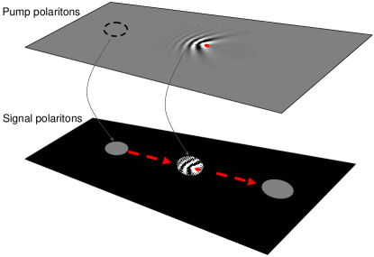
The images reflect the addition of two different contributions: () the pump polaritons (extended in an area of m2) which constantly feed the signal polariton, and () the motion of the signal polaritons by themselves, which pass through the defects. Figure 18 illustrates how these two contributions are detected at the signal polariton energy. The fringes observed around the defects appear due to the local change in density of the pump polaritons, which is reflected in the structure of the signal.
The pump polaritons are injected in a coherent state, at high energies, high density and with high -vector. At such high momentum pump polaritons interact with the defects giving rise to interference waves in the upstream direction. This interaction is analogous to that observed in an atomic condensate flowing at a speed higher than its sound speed against a potential barrier [Carusotto2006]. The same prediction has been established [Ciuti2005] and recently observed [Amo2008] for the case of polaritons under resonant excitation by a single pump field. By contrast, when the flow speed is lower than the sound speed (subsonic), a superfluid in the macroscopically occupied condensate is expected [Onofrio2000, Ciuti2005].
It is important to note that the visibility of these waves does not imply that the signal polaritons are also in such a perturbed regime. On the contrary, the signal polaritons (which are at lower energy and wavevector) seem to flow unperturbed when passing through the defects. In fact, figure 17 (b) shows that the signal polaritons present a very narrow and well defined momentum (evidencing its quantum-state nature) that hardly changes when passing through the defects. This non scattering behaviour of signal polaritons evidences their superfluid character: excitations in the droplet are inhibited while it passes through the obstacle, equivalent to the subsonic situation described above.
The key element to understand the coherent propagation of the polariton droplet revealed in figure 17, is the linear dispersion shown in figure 14. All particles in the packet remain in phase and at the same group velocity, preventing its diffusion both in real and momentum spaces, even when flowing through localized defects. Other examples of coherent motion through defects of different sizes can be found in [Amo2009]. As recently shown theoretically, solitonic solutions are expected in semiconductor microcavities under OPO operation in the presence of a linearized dispersion [Egorov2009]. However these solutions are restricted to one-dimensional architectures, for very precise values of the pump momentum, with solitons which are extended over the ensemble of signal, pump and idler modes. Contrary to that, our results show wavepacket propagation in two-dimension, for the signal state, for a number of pump momentum realizations (not shown).
5 Summary and future perspectives
In the first part of this tutorial we have presented experimental results demonstrating the capability to optically control in a short time-scale ( ps) the distributions of carriers in QWs. In particular, we have seen that the arrival of a short light pulse results in a sudden warming of a pre-excited electron-hole plasma. The exciton distributions, which are in thermal equilibrium with the electron-hole plasma, are also abruptly warmed-up by the arrival of the pulse, resulting in an ultrafast dip in the hh-exciton luminescence.
We have introduced a model that quantitatively reproduces the observed luminescence quenching and can be used to obtain the relative increase in carrier/exciton temperature induced by the arrival of the pulse, by measuring the magnitude of the dip in the hh-exciton PL.
This model has been used to study the polariton relaxation from the reservoir states to the bottom of the LPB in semiconductor microcavities. Understanding the mechanisms of this relaxation is of great importance to improve the design of microcavites with enhanced conditions for the spontaneous condensation of polaritons. In the studied microcavities, under non-resonant excitation, condensation could not be observed at any detuning. By contrast, the transition from the strong to the weak coupling regimes and the simultaneous onset of lasing is observed, and reported in detail, when the excitation density is increased above a certain threshold.
In the final part of the tutorial we have presented an experimental configuration based on the optical parametric oscillator regime, which allows for the creation and detection of polariton quantum fluids with a non-zero momentum. The high pump-polariton density renormalizes the LPB and changes its shape, due to the strong polariton interactions. The generated signal fluid lives on top of a linearized dispersion and shows no diffusion in both real and momentum space. Furthermore, the signal packet is able to traverse defects encountered in its flow path without scattering. These observations are compatible with the description of the signal fluid as a superfluid.
The phenomenology associated to bosonic quantum fluids has just been uncovered in atomic condensates in the past decade, and the subtle links between condensation and superfluidity have been only recently established [Legget1999]. For instance, in the regime of quantum reflections, very rich effects have been recently observed [Pasquini2004, Pasquini2006] and studied theoretically [Scott2005, Scott2007, Martin2007] in atomic BECs interacting with surfaces. There is plenty of room for the exploration of these effects in semiconductor microcavities, with the advantage of the simple implementation of barriers and defects with on-demand shapes and sizes by use of lithographic techniques [Lai2007b, Kim2007].
Faraday waves [Engels2007] and Josephson oscillations [Raghavan1999, Albiez2005, Levy2007] already observed in atomic condensates are some of the phenomena which could be directly explored in semiconductor microcavities [Sarchi2008], for instance by use of surface acoustic waves [deLima2006] or by creating two nearby-connected polariton condensates [Shelykh2008].
Additionally, the dynamic (rather than thermal) equilibrium in a semiconductor microcavity caused by the constant introduction and escape of polaritons in the system, presents important differences to the atomic case. These differences result in a rich phenomenology unaccessible with the study of atomic condensates. First studies in this direction are the spontaneous formation of full [Lagoudakis2008, Keeling2008] and half vortices [Rubo2007, Lagoudakis2009] without stirring of the condensate, and the appearance of a diffusive Goldstone mode in the OPO regime [Wouters2007b, Ballarini2009].
In semiconductor microcavities, condensates and fluids are easily manipulated with the excitation laser-beams, and are currently created with standard liquid-He cryogenic techniques, at 5-20 K. Furthermore, wide bandgap systems, such as those based on GaN have already shown very promising results [Christopoulos2007, Christmann2008] on the prospective creation of Bose-Einstein polariton condensates at room temperature.
Acknowledgments
This work was performed in collaboration with D. Ballarini, M. D. Martín, L. Klopotowski, F. P. Laussy, E. del Valle, C. Tejedor, E. Kozhemiakina, A. I. Toropov, K. S. Zhuravlev, D. Krizhanovskii, M. S. Skolnick, D. Bajoni and J. Bloch. This work would have not been possible without the high quality samples designed and grown by A. Lemaître, J. Bloch, J. S. Roberts and M. S. Skolnick. We thank the Spanish MEC (MAT2008-01555/NAN and QOIT-CSD2006-00019), CAM (S-0505/ESP-0200), and the IMDEA Nanociencia for funding. AA acknowledges financial support for the realization of the PhD thesis from the FPU program of the Spanish Ministry of Science and Education, D S the Ramón y Cajal program.
References
References
- [1] \harvarditemAbo-Shaeer et al.2001Abo-Shaeer2001 Abo-Shaeer J R, Raman C, Vogels J M \harvardand Ketterle W 2001 Science 292(5516), 476.
- [2] \harvarditemAlbiez et al.2005Albiez2005 Albiez M, Gati R, Folling J, Hunsmann S, Cristiani M \harvardand Oberthaler M K 2005 Phys. Rev. Lett. 95(1), 010402.
- [3] \harvarditemAlexandrou et al.1995Alexandrou1995 Alexandrou A, Berger V \harvardand Hulin D 1995 Phys. Rev. B 52(7), 4654.
- [4] \harvarditemAllum et al.1977Allum1977 Allum D R, McClintock P V E, Phillips A \harvardand Bowley R M 1977 Phil. Trans. R. Soc. Lond. A 284(1320), 179.
- [5] \harvarditemAmo et al.2008Amo2008b Amo A, Ballarini D, Sanvitto D, Kozhemyakina E, Viña L, Lemaître A, Bajoni D \harvardand Bloch J 2008 Appl. Phys. Lett. 92(6), 061912.
- [6] \harvarditemAmo et al2009bAmo2008 Amo A, Lefrère J, Pigeon S, Adrados C, Ciuti C, Carusotto I, Houdré R, Giacobino E \harvardand Bramati A 2009b Nature Phys. 5, 805.
- [7] \harvarditemAmo et al2009cAmo2009c Amo A, Liew T C H, Adrados C, Giacobino E, Kavokin A V \harvardand Bramati A 2009c Phys. Rev. B 80(16), 165325.
- [8] \harvarditemAmo et al.2006Amo2006 Amo A, Martín M D, Viña L, Toropov A I \harvardand Zhuravlev K S 2006 Phys. Rev. B 73(3), 035205.
- [9] \harvarditemAmo et al2009aAmo2009 Amo A, Sanvitto D, Laussy F P, Ballarini D, del Valle E, Martín M D, Lemaître A, Bloch J, Krizhanovskii D N, Skolnick M S, Tejedor C \harvardand Viña L 2009a Nature 457(7227), 291.
- [10] \harvarditemAmo et al.2007Amo2007b Amo A, Viña L, Lugli P, Tejedor C, Toropov A I \harvardand Zhuravlev K S 2007 Phys. Rev. B 75(8), 085202.
- [11] \harvarditemBaars et al.2000Baars2000 Baars T, Bayer M, Forchel A, Schäfer F \harvardand Reithmaier J P 2000 Phys. Rev. B 61(4), R2409.
- [12] \harvarditemBaas et al.2004Baas2004 Baas A, Karr J P, Romanelli M, Bramati A \harvardand Giacobino E 2004 Phys. Rev. B 70(16), 161307.
- [13] \harvarditemBajoni et al.2006Bajoni2006 Bajoni D, Perrin M, Senellart P, Lemaître A, Sermage B \harvardand Bloch J 2006 Phys. Rev. B 73(20), 205344.
- [14] \harvarditemBajoni et al.unpublishedBajoni2006b Bajoni D, Perrin M, Senellart P, Lemaître A, Sermage B \harvardand Bloch J unpublished.
- [15] \harvarditemBajoni et al.2007Bajoni2007 Bajoni D, Senellart P, Lemaître A \harvardand Bloch J 2007 Phys. Rev. B 76, 201305(R).
- [16] \harvarditemBajoni et al.2008Bajoni2008 Bajoni D, Senellart P, Wertz E, Sagnes I, Miard A, Lemaître A \harvardand Bloch J 2008 Phys. Rev. Lett. 100, 047401.
- [17] \harvarditemBalili et al.2007Balili2007 Balili R, Hartwell V, Snoke D, Pfeiffer L \harvardand West K 2007 Science 316(5827), 1007.
- [18] \harvarditemBallarini et al.2007Ballarini2007 Ballarini D, Amo A, Sanvitto D, Viña L, Skolnick M \harvardand Roberts J 2007 Appl. Phys. Lett. 90, 201905.
- [19] \harvarditemBallarini et al.2009Ballarini2009 Ballarini D, Sanvitto D, Amo A, Viña L, Wouters M, Carusotto I, Lemaître A \harvardand Bloch J 2009 Phys. Rev. Lett. 102, 056402.
- [20] \harvarditemBaumberg et al.2008Baumberg2008 Baumberg J J, Kavokin A V, Christopoulos S, Grundy A J D, Butté R, Christmann G, Solnyshkov D D, Malpuech G, Baldassarri Hoger von Hogersthal G, Feltin E, Carlin J F \harvardand Grandjean N 2008 Phys. Rev. Lett. 101(13), 136409.
- [21] \harvarditemBilykh et al.2009Bilykh2009 Bilykh V V, Nguyen M H, Sibeldin N N, Skorikov M L, Tsvetkov V A \harvardand Sharkov A V 2009 J. Exp. Theor. Phys. 109(3), 472.
- [22] \harvarditemBloch \harvardand Marzin1997Bloch1997 Bloch J \harvardand Marzin J Y 1997 Phys. Rev. B 56(4), 2103.
- [23] \harvarditemBloch et al.2002Bloch2002 Bloch J, Sermage B, Jacquot C, Senellart P \harvardand Thierry-Mieg V 2002 Phys. Stat. Sol. (a) 190(3), 827.
- [24] \harvarditemButov et al.2002Butov2002 Butov L V, Gossard A C \harvardand Chemla D S 2002 Nature 418(6899), 751.
- [25] \harvarditemButté et al.2002Butte2002a Butté R, Delalleau G, Tartakovskii A I, Skolnick M S, Astratov V N, Baumberg J J, Malpuech G, Di Carlo A, Kavokin A V \harvardand Roberts J S 2002 Phys. Rev. B 65(20), 205310.
- [26] \harvarditemButté et al.2003Butte2002b Butté R, Skolnick M S, Whittaker D M, Bajoni D \harvardand Roberts J S 2003 Phys. Rev. B 68(15(I)), 115325.
- [27] \harvarditemCapizzi et al.1984Capizzi1984 Capizzi M, Modesti S, Frova A, Staehli J L, Guzzi M \harvardand Logan R A 1984 Phys. Rev. B 29(4), 2028.
- [28] \harvarditemCarusotto \harvardand Ciuti2004Carusotto2004 Carusotto I \harvardand Ciuti C 2004 Phys. Rev. Lett. 93(16), 166401.
- [29] \harvarditemCarusotto et al.2006Carusotto2006 Carusotto I, Hu S X, Collins L A \harvardand Smerzi A 2006 Phys. Rev. Lett. 97, 260403.
- [30] \harvarditemChatterjee et al.2004Chatterjee2004 Chatterjee S, Ell C, Mosor S, Khitrova G, Gibbs H M, Hoyer W, Kira M, Koch S W, Prineas J P \harvardand Stolz H 2004 Phys. Rev. Lett. 92(6), 067402.
- [31] \harvarditemChevy et al.2000Chevy2000 Chevy F, Madison K W \harvardand Dalibard J 2000 Phys. Rev. Lett. 85(11), 2223.
- [32] \harvarditemChristmann et al.2008Christmann2008 Christmann G, Butté R, Feltin E, Carlin J F \harvardand Grandjean N 2008 Appl. Phys. Lett. 93, 051102.
- [33] \harvarditemChristopoulos et al.2007Christopoulos2007 Christopoulos S, Baldassarri Hoger von Hogersthal G, Grundy A J D, Lagoudakis P G, Kavokin A V, Baumberg J J, Christmann G, Butté R, Feltin E, Carlin J F \harvardand Grandjean N 2007 Phys. Rev. Lett. 98(12), 126405.
- [34] \harvarditemCiuti \harvardand Carusotto2005Ciuti2005 Ciuti C \harvardand Carusotto I 2005 Phys. Stat. Sol. (b) 242(11), 2224.
- [35] \harvarditemCiuti et al.1998Ciuti1998 Ciuti C, Savona V, Piermarocchi C, Quattropani A \harvardand Schwendimann P 1998 Phys. Rev. B 58(16), R10123.
- [36] \harvarditemCiuti et al.2001Ciuti2001 Ciuti C, Schwendimann P \harvardand Quattropani A 2001 Phys. Rev. B 63(4), 041303.
- [37] \harvarditemCohen-Tannoudji et al.1977Cohen1977 Cohen-Tannoudji C, Diu B \harvardand Laloë F 1977 Quantum Mechanics, vols. I and II Hermann Paris, France.
- [38] \harvarditemDamen et al.1991Damen1991 Damen T C, Viña L, Cunningham J E, Shah J \harvardand Sham L J 1991 Phys. Rev. Lett. 67(24), 3432.
- [39] \harvarditemDang et al.1998Dang1998 Dang L S, Heger D, André R, Boeuf F \harvardand Romestain R 1998 Phys. Rev. Lett. 81(18), 3920.
- [40] \harvarditemde Lima Jr. et al.2006deLima2006 de Lima Jr. M M, van der Poel M, Santos P V \harvardand Hvam J M 2006 Phys. Rev. Lett. 97(4), 045501.
- [41] \harvarditemdel Valle et al.2009delValle2009 del Valle E, Sanvitto D, Amo A, Laussy F P, André R, Tejedor C \harvardand Viña L 2009 Phys. Rev. Lett. 103(9), 096404.
- [42] \harvarditemDemenev et al.2009Demenev2008 Demenev A A, Shchekin, A A, Larionov A V, Gavrilov S S, Kulakovskii V D, Gippius N A \harvardand Tikhodeev S G 2008 Phys. Rev. Lett. 101(13), 136401.
- [43] \harvarditemDeng et al.2006Deng2006 Deng H, Press D, Gotzinger S, Solomon G S, Hey R, Ploog K H \harvardand Yamamoto Y 2006 Phys. Rev. Lett. 97(14), 146402.
- [44] \harvarditemDeng et al.2007Deng2007 Deng H, Solomon G S, Hey R, Ploog K H \harvardand Yamamoto Y 2007 Phys. Rev. Lett. 99(12), 126403.
- [45] \harvarditemDoan et al.2005Doan2005 Doan T D, Cao H T, Thoai D B T \harvardand Haug H 2005 Phys. Rev. B 72(8), 085301.
- [46] \harvarditemDzhioev et al.2002Dzhioev2002 Dzhioev R I, Kavokin K V, Korenev V L, Lazarev M V, Meltser B Y, Stepanova M N, Zakharchenya B P, Gammon D \harvardand Katzer D S 2002 Phys. Rev. B 66, 245204.
- [47] \harvarditemEgorov et al.2009Egorov2009 Egorov O A, Skryabin D V, Yulin A V \harvardand Lederer F 2009 Phys. Rev. Lett. 102(15), 153904.
- [48] \harvarditemEiermann et al.2003Eiermann2003 Eiermann B, Treutlein P, Anker T, Albiez M, Taglieber M, Marzlin K P \harvardand Oberthaler M K 2003 Phys. Rev. Lett. 91(6), 060402.
- [49] \harvarditemEllis et al.1980Ellis1980 Ellis T, Jewell C I \harvardand McClintock P V E 1980 Phys. Lett. A 78(4), 358.
- [50] \harvarditemEngels et al.2007Engels2007 Engels P, Atherton C \harvardand Hoefer M A 2007 Phys. Rev. Lett. 98(9), 095301.
- [51] \harvarditemFort et al.2005Fort2005 Fort C, Fallani L, Guarrera V, Lye J E, Modugno M, Wiersma D S \harvardand Inguscio M 2005 Phys. Rev. Lett. 95(17), 170410.
- [52] \harvarditemFreixanet et al.2000Freixanet2000 Freixanet T, Sermage B, Tiberj A \harvardand Planel R 2000 Phys. Rev. B 61(11), 7233.
- [53] \harvarditemHess \harvardand Fairbank1967Hess1967 Hess G B \harvardand Fairbank W M 1967 Phys. Rev. Lett. 19(5), 216.
- [54] \harvarditemHoyer et al.2005Hoyer2005 Hoyer W, Ell C, Kira M, Koch S W, Chatterjee S, Mosor S, Khitrova G, Gibbs H M \harvardand Stolz H 2005 Phys. Rev. B 72, 075324.
- [55] \harvarditemHuynh et al.2003Huynh2003 Huynh A, Tignon J, Keller G, Roussignol P, Delalande C, André R, Romestain R \harvardand Dang L S 2003 Phys. Rev. B 68(16), 165340.
- [56] \harvarditemImamoglu et al.1996Imamoglu1996 Imamoglu A, Ram R J, Pau S \harvardand Yamamoto Y 1996 Phys. Rev. A 53(6), 4250.
- [57] \harvarditemKaindl et al.2003Kaindl2003 Kaindl R A, Carnahan M A, Högele D, L venich R \harvardand Chemla D S 2003 Nature 423, 734.
- [58] \harvarditemKalevich et al.2001Kalevich2001 Kalevich V K, Paillard M, Kavokin K V, Marie X, Kovsh A R, Amand T, Zhukov A E, Musikhin Y G, Ustinov V M, Vanelle E \harvardand Zakharchenya B P 2001 Phys. Rev. B 64(4), 045309.
- [59] \harvarditemKappei et al.2005Kappei2005 Kappei L, Szczytko J, Morier-Genoud F \harvardand Deveaud B 2005 Phys. Rev. Lett. 94, 147403.
- [60] \harvarditemKarr et al.2004Karr2004 Karr J P, Baas A, Houdré R \harvardand Giacobino E 2004 Phys. Rev. A 69(3), 031802.
- [61] \harvarditemKasprzak et al.2007Kasprzak2007 Kasprzak J, André R, Dang L S, Shelykh I A, Kavokin A V, Rubo Y G, Kavokin K V \harvardand Malpuech G 2007 Phys. Rev. B 75(4), 045326.
- [62] \harvarditemKasprzak, Richard, Baas, Deveaud, André, Poizat \harvardand Dang2008Kasprzak2008 Kasprzak J, Richard M, Baas A, Deveaud B, André R, Poizat J P \harvardand Dang L S 2008 Phys. Rev. Lett. 100(6), 067402.
- [63] \harvarditemKasprzak et al.2006Kasprzak2006 Kasprzak J, Richard M, Kundermann S, Baas A, Jeambrun P, Keeling J M J, Marchetti F M, Szymanska M H, André R, Staehli J L, Savona V, Littlewood P B, Deveaud B \harvardand Dang L S 2006 Nature 443(7110), 409.
- [64] \harvarditemKasprzak, Solnyshkov, André, Dang \harvardand Malpuech2008Kasprzak2008b Kasprzak J, Solnyshkov D D, André R, Dang L S \harvardand Malpuech G 2008 Phys. Rev. Lett. 101(14), 146404.
- [65] \harvarditemKavokin et al.2007Kavokin2007 Kavokin A, Baumberg J J, Malpuech G \harvardand Laussy F P 2007 Microcavities Oxford University Press Inc. New York.
- [66] \harvarditemKavokin et al.2003Kavokin2003c Kavokin A, Malpuech G \harvardand Laussy F P 2003 Phys. Lett. A 306(4), 187.
- [67] \harvarditemKeeling2008Keeling2008b Keeling J 2008 Phys. Rev. B 78(20), 205316.
- [68] \harvarditemKeeling \harvardand Berloff2008Keeling2008 Keeling J \harvardand Berloff N G 2008 Phys. Rev. Lett. 100(25), 250401.
- [69] \harvarditemKeeling \harvardand Berloff2009Keeling2009 Keeling J \harvardand Berloff N G 2009 Nature 457(7227), 273.
- [70] \harvarditemKeeling et al.2004Keeling2004b Keeling J, Eastham P R, Szymanska M H \harvardand Littlewood P B 2004 Phys. Rev. Lett. 93(22), 226403.
- [71] \harvarditemKeeling et al.2007Keeling2007 Keeling J, Marchetti F M, Szymańska M H \harvardand Littlewood P B 2007 Semicond. Sci. Technol. 22(5), R1.
- [72] \harvarditemKim et al.2007Kim2007 Kim N Y, Lai C W, Utsunomiya S, Roumpos G, Deng H, Byrnes T, Recher P, Kumada N, Fujisawa T \harvardand Yamamoto Y 2007 in ‘9th International conference on the Optics of Excitons in Confined Systems’ Patti, Italy.
- [73] \harvarditemKlopotowski et al.2006Klopotowski2006 Klopotowski L, Martín M, Amo A, Viña L, Shelykh I, Glazov M, Malpuech G, Kavokin A \harvardand André R 2006 Solid State Commun. 139(10), 511.
- [74] \harvarditemKnox1992Knox1992 Knox W H 1992 in J Shah, ed., ‘Hot Carriers in Semiconductor Nanostructures: Physics and Applications’ Academic Press, Inc. Boston.
- [75] \harvarditemKoch et al.2006Koch2006 Koch S W, Kira M, Khitrova G \harvardand Gibbs H M 2006 Nature Mater. 5, 523.
- [76] \harvarditemKrizhanovskii et al.2009Krizhanovskii2009 Krizhanovskii D N, Lagoudakis K G, Wouters M, Pietka B, Bradley R A, Guda K, Whittaker D M, Skolnick M S, Deveaud-Pledran B, Richard M, André R \harvardand Dang L S 2009 Phys. Rev. B 80(4), 045317.
- [77] \harvarditemKrizhanovskii et al.2004Krizhanovskii2004 Krizhanovskii D N, Tartakovskii A I, Makhonin M N, Dremin A N \harvardand Kulakovskii V D 2004 Phys. Rev. B 70(19), 195303.
- [78] \harvarditemLagoudakis et al.2009Lagoudakis2009 Lagoudakis K G, Ostatnicky T, Kavokin A V, Rubo Y G, André R \harvardand Deveaud-Pledran B 2009 Science 326(5955), 974.
- [79] \harvarditemLagoudakis et al.2008Lagoudakis2008 Lagoudakis K G, Wouters M, Richard M, Baas A, Carusotto I, André R, Dang L S \harvardand Deveaud-Pledran B 2008 Nature Phys. 4(9), 706.
- [80] \harvarditemLagoudakis et al.2004Lagoudakis2004 Lagoudakis P G, Martín M D, Baumberg J J, Malpuech G \harvardand Kavokin A 2004 J. Appl. Phys. 95(5), 2487.
- [81] \harvarditemLagoudakis et al.2003Lagoudakis2003 Lagoudakis P G, Martín M D, Baumberg J J, Qarry A, Cohen E \harvardand Pfeiffer L N 2003 Phys. Rev. Lett. 90(20), 206401.
- [82] \harvarditemLai et al.2007Lai2007b Lai C W, Kim N Y, Utsunomiya S, Roumpos G, Deng H, Fraser M D, Byrnes T, Recher P, Kumada N, Fujisawa T \harvardand Yamamoto Y 2007 Nature 450, 529.
- [83] \harvarditemLandau \harvardand Lifshitz1986Landau1986 Landau E \harvardand Lifshitz L 1986 Statistical Physics, Parts I and II Vol. 5 of Course of Theoretical Physics Pergamon Press.
- [84] \harvarditemLangbein et al.2007Langbein2007 Langbein W, Shelykh I, Solnyshkov D, Malpuech G, Rubo Y \harvardand Kavokin A 2007 Phys. Rev. B 75(7), 075323.
- [85] \harvarditemLarionova et al.2008Larionova2008 Larionova Y, Stolz W \harvardand Weiss C O 2008 Opt. Lett. 33(4), 321–323.
- [86] \harvarditemLaussy et al.2004Laussy2004b Laussy F P, Malpuech G, Kavokin A \harvardand Bigenwald P 2004 Phys. Rev. Lett. 93(1), 016402.
- [87] \harvarditemLaussy et al.2006Laussy2006 Laussy F P, Shelykh I A, Malpuech G \harvardand Kavokin A 2006 Phys. Rev. B 73(3), 035315.
- [88] \harvarditemLeggett1999Legget1999 Leggett A J 1999 Rev. Mod. Phys. 71(2), S318.
- [89] \harvarditemLeggett2001Leggett2001 Leggett A J 2001 Rev. Mod. Phys. 73(2), 307.
- [90] \harvarditemLeo et al.1988aLeo1988 Leo K, Rühle W W \harvardand Ploog K 1988a Phys. Rev. B 38(3), 1947.
- [91] \harvarditemLeo et al.1988bLeo1988b Leo K, Rühle W W, Queisser H J \harvardand Ploog K 1988b Phys. Rev. B 37(12), 7121.
- [92] \harvarditemLevy et al.2007Levy2007 Levy S, Lahoud E, Shomroni I \harvardand Steinhauer J 2007 Nature 449(7162), 579.
- [93] \harvarditemLove et al.2008Love2008 Love A P D, Krizhanovskii D N, Whittaker D M, Bouchekioua R, Sanvitto D, Rizeiqi S A, Bradley R, Skolnick M S, Eastham P R, André R \harvardand Dang L S 2008 Phys. Rev. Lett. 101(6), 067404.
- [94] \harvarditemMadison et al.2000Madison2000 Madison K W, Chevy F, Wohlleben W \harvardand Dalibard J 2000 Phys. Rev. Lett. 84(5), 806.
- [95] \harvarditemMalpuech et al.2002aMalpuech2002 Malpuech G, Carlo A D, Kavokin A V, Baumberg J J, Zamfirescu M \harvardand Lugli P 2002a Appl. Phys. Lett. 81(3), 412.
- [96] \harvarditemMalpuech et al.2002bMalpuech2002b Malpuech G, Kavokin A, Di Carlo A \harvardand Baumberg J J 2002b Phys. Rev. B 65(15), 153310.
- [97] \harvarditemMalpuech et al.2003Malpuech2003 Malpuech G, Rubo Y G, Laussy F P, Bigenwald P \harvardand Kavokin A V 2003 Semicond. Sci. Technol. 18, S395.
- [98] \harvarditemMalpuech et al.2007Malpuech2007 Malpuech G, Solnyshkov D D, Ouerdane H, Glazov M M \harvardand Shelykh I 2007 Phys. Rev. Lett. 98, 206402.
- [99] \harvarditemMarchetti et al.2008Marchetti2008 Marchetti F M, Szymanska M H, Keeling J M J, Kasprzak J, André R, Littlewood P B \harvardand Dang L S 2008 Phys. Rev. Lett. 77(23), 235313.
- [100] \harvarditemMartin et al.2007aMartin2007 Martin A M, Scott R G \harvardand Fromhold T M 2007a Phys. Rev. A 75(6), 065602.
- [101] \harvarditemMartín et al.2007bMartin2007b Martín M D, Aichmayr G, Amo A, Ballarini D, Klopotowski L \harvardand Viña L 2007b J. Phys.: Condens. Matter 19(29), 295204.
- [102] \harvarditemMartín et al.2002Martin2002b Martín M D, Aichmayr G, Viña L \harvardand André R 2002 Phys. Rev. Lett. 89(7), 077402.
- [103] \harvarditemMartín et al.2005Martin2005 Martín M D, Ballarini D, Amo A, Klopotowsi L, Viña L, Kavokin A V \harvardand André R 2005 Phys. Stat. Sol. (c) 2(11), 3880.
- [104] \harvarditemMartin-Regalado et al.1997Martin-Regalado1997 Martin-Regalado J, Prati F, San Miguel M \harvardand Abraham N 1997 IEEE J. Quantum Electron. 33(5), 765.
- [105] \harvarditemNardin et al.2009Nardin2009 Nardin G, Lagoudakis K G, Wouters M, Richard M, Baas A, André R, Dang L S, Pietka B \harvardand Deveaud-Pledran B 2009 arXiv:0905.2337v2 .
- [106] \harvarditemNelsen et al.2009Nelsen2009 Nelsen B, Balili R, Snoke D W, Pfeiffer L \harvardand West K 2009 J. Appl. Phys. 105(12), 122414.
- [107] \harvarditemNemec et al.2005Nemec2005 Nemec P, Kerachian Y, van Driel H M \harvardand Smirl A L 2005 Phys. Rev. B 72, 245202.
- [108] \harvarditemOno et al.2002Ono2002 Ono K, Austing D G, Tokura Y \harvardand Tarucha S 2002 Science 297(5585), 1313.
- [109] \harvarditemOnofrio et al.2000Onofrio2000 Onofrio R, Raman C, Vogels J M, Abo-Shaeer J R, Chikkatur A P \harvardand Ketterle W 2000 Phys. Rev. Lett. 85(11), 2228.
- [110] \harvarditemPackard \harvardand Sanders1972Packard1972 Packard R E \harvardand Sanders T M 1972 Phys. Rev. A 6(2), 799–807.
- [111] \harvarditemPasquini et al.2006Pasquini2006 Pasquini T A, Saba M, Jo G B, Shin Y, Ketterle W, Pritchard D E, Savas T A \harvardand Mulders N 2006 Phys. Rev. Lett. 97(9), 093201.
- [112] \harvarditemPasquini et al.2004Pasquini2004 Pasquini T A, Shin Y, Sanner C, Saba M, Schirotzek A, Pritchard D E \harvardand Ketterle W 2004 Phys. Rev. Lett. 93(22), 223201.
- [113] \harvarditemPau et al.1996Pau1996 Pau S, Cao H, Jacobson J, Bj rk G, Yamamoto Y \harvardand Imamoglu A 1996 Phys. Rev. A 54(3), R1789.
- [114] \harvarditemPerrin et al.2005aPerrin2005 Perrin M, Bloch J, Lemaître A \harvardand Senellart P 2005a Phys. Stat. Sol. (c) 2(2), 759.
- [115] \harvarditemPerrin et al.2005bPerrin2005b Perrin M, Senellart P, Lemaître A \harvardand Bloch J 2005b Phys. Rev. B 72(7), 075340.
- [116] \harvarditemPitaevskii \harvardand Strindgari2003Pitaevskii2003 Pitaevskii L \harvardand Strindgari S 2003 Bose-Einsten Condensation 1st edn Clarendon Press Oxford.
- [117] \harvarditemPotemski et al.1999Potemski1999 Potemski M, Perez E, Martín D, Viña L, Gravier L, Fisher A \harvardand Ploog K 1999 Solid State Commun. 110(3), 163.
- [118] \harvarditemRaghavan et al.1999Raghavan1999 Raghavan S, Smerzi A, Fantoni S \harvardand Shenoy S R 1999 Phys. Rev. A 59(1), 620.
- [119] \harvarditemRaman et al.1999Raman1999 Raman C, K hl M, Onofrio R, Durfee D S, Kuklewicz C E, Hadzibabic Z \harvardand Ketterle W 1999 Phys. Rev. Lett. 83(13), 2502.
- [120] \harvarditemRead et al.2009Read2009 Read D, Liew T C H, Rubo Y G \harvardand Kavokin A V 2009 Phys. Rev. B 80(19), 195309.
- [121] \harvarditemRichard et al.2005Richard2005 Richard M, Kasprzak J, André R, Romestain R, Dang L S, Malpuech G \harvardand Kavokin A 2005 Phys. Rev. B 72, 201301(R).
- [122] \harvarditemRomanelli et al.2007Romanelli2007 Romanelli M, Leyder C, Karr J P, Giacobino E \harvardand Bramati A 2007 Phys. Rev. Lett. 98(10), 106401.
- [123] \harvarditemRota et al.1993Rota1993b Rota L, Lugli P, Elsaesser T \harvardand Shah J 1993 Phys. Rev. B 47(8), 4226.
- [124] \harvarditemRubo2007Rubo2007 Rubo Y G 2007 Phys. Rev. Lett. 99(10), 106401.
- [125] \harvarditemRyu et al.2007Ryu2007 Ryu C, Andersen M F, Clade P, Natarajan V, Helmerson K \harvardand Phillips W D 2007 Phys. Rev. Lett. 99(26), 260401.
- [126] \harvarditemSanvitto et al.2009bSanvitto2009b Sanvitto D, Amo A, Viña L, André R, Solnyshkov D \harvardand Malpuech G 2009b Phys. Rev. B 80(4), 045301.
- [127] \harvarditemSanvitto et al.2009aSanvitto2009 Sanvitto D, Marchetti F M, Szymanska M H, Tosi G, Baudisch M, Laussy F P, Krizhanovskii D N, Skolnick M S, Marrucci L, Lemaître A, Bloch J, Tejedor C \harvardand Viña L 2009a arXiv:0907.2371v2 .
- [128] \harvarditemSanvitto et al.2005Sanvitto2005b Sanvitto D, Whittaker D M, Skolnick M S \harvardand Roberts J S 2005 Phys. Stat. Sol. (a) 202(3), 353.
- [129] \harvarditemSarchi et al.2008Sarchi2008 Sarchi D, Carusotto I, Wouters M \harvardand Savona V 2008 Phys. Rev. B 77(12), 125324.
- [130] \harvarditemSargent et al.1987Sargent1987 Sargent M, Scully M O \harvardand Lamb W E 1987 Laser Physics Addison-Wesley Reading, MA.
- [131] \harvarditemSavona et al.1999Savona1999 Savona V, Piermarocchi C, Quattropani A, Schwendimann P \harvardand Tassone F 1999 Phase Transitions 68(1), 169.
- [132] \harvarditemSavvidis et al.2000Savvidis2000 Savvidis P G, Baumberg J J, Stevenson R M, Skolnick M S, Whittaker D M \harvardand Roberts J S 2000 Phys. Rev. Lett. 84(7), 1547.
- [133] \harvarditemScheuer \harvardand Orenstein1999Scheuer1999 Scheuer J \harvardand Orenstein M 1999 Science 285(5425), 230.
- [134] \harvarditemScott et al.2007Scott2007 Scott R G, Gardiner C W \harvardand Hutchinson D A W 2007 Laser Phys. 17(4), 527.
- [135] \harvarditemScott et al.2005Scott2005 Scott R G, Martin A M, Fromhold T M \harvardand Sheard F W 2005 Phys. Rev. Lett. 95(7), 073201.
- [136] \harvarditemSelbmann et al.1996Selbmann1996 Selbmann P E, Gulia M, Rossi F, Molinari E \harvardand Lugli P 1996 Phys. Rev. B 54(7), 4660.
- [137] \harvarditemSenellart et al.2000Senellart2000 Senellart P, Bloch J, Sermage B \harvardand Marzin J Y 2000 Phys. Rev. B 62(24), R16263.
- [138] \harvarditemSermage et al.1996Sermage1996 Sermage B, Long S, Abram I, Marzin J Y, Bloch J, Planel R \harvardand Thierry-Mieg V 1996 Phys. Rev. B 53(24), 16516.
- [139] \harvarditemSermage et al.2001Sermage2001 Sermage B, Malpuech G, Kavokin A V \harvardand Thierry-Mieg V 2001 Phys. Rev. B 64(8), 081303.
- [140] \harvarditemShelykh et al.2010Shelykh2010 Shelykh I A, Kavokin A V, Rubo Y G, Liew T C H \harvardand Malpuech G 2010 Semicond. Sci. Technol. 25(1), 013001.
- [141] \harvarditemShelykh et al.2006Shelykh2006 Shelykh I A, Rubo Y G, Malpuech G, Solnyshkov D D \harvardand Kavokin A 2006 Phys. Rev. Lett. 97(6), 066402.
- [142] \harvarditemShelykh et al.2008Shelykh2008 Shelykh I A, Solnyshkov D D, Pavlovic G \harvardand Malpuech G 2008 Phys. Rev. B 78(4), 041302.
- [143] \harvarditemSteinhauer et al.2002Steinhauer2002 Steinhauer J, Ozeri R, Katz N \harvardand Davidson N 2002 Phys. Rev. Lett. 88(12), 120407.
- [144] \harvarditemStern et al.2008Stern2008 Stern M, Garmider V, Umansky V \harvardand Bar-Joseph I 2008 Phys. Rev. Lett. 100(25), 256402.
- [145] \harvarditemStevenson et al.2000Stevenson2000 Stevenson R M, Astratov V N, Skolnick M S, Whittaker D M, Emam-Ismail M, Tartakovskii A I, Savvidis P G, Baumberg J J \harvardand Roberts J S 2000 Phys. Rev. Lett. 85(17), 3680.
- [146] \harvarditemSzczytko et al.2004Szczytko2004 Szczytko J, Kappei L, Berney J, Morier-Genoud F, Portella-Oberli M \harvardand Deveaud B 2004 Phys. Rev. Lett. 93, 137401.
- [147] \harvarditemSzczytko et al.2005Szczytko2005 Szczytko J, Kappei L, Berney J, Morier-Genoud F, Portella-Oberli M \harvardand Deveaud B 2005 Phys. Rev. B 71(19), 195313.
- [148] \harvarditemSzymanska et al.2006Szymanska2006 Szymanska M H, Keeling J \harvardand Littlewood P B 2006 Phys. Rev. Lett. 96(23), 230602.
- [149] \harvarditemSzymanska \harvardand Littlewood2002Szymanska2002 Szymanska M H \harvardand Littlewood P B 2002 Solid State Commun. 124(3), 103.
- [150] \harvarditemTartakovskii et al.2000Tartakovskii2000 Tartakovskii A I, Emam-Ismail M, Stevenson R M, Skolnick M S, Astratov V N, Whittaker D M, Baumberg J J \harvardand Roberts J S 2000 Phys. Rev. B 62(4), R2283.
- [151] \harvarditemTartakovskii et al.2003Tartakovskii2003 Tartakovskii A I, Krizhanovskii D N, Malpuech G, Emam-Ismail M, Chernenko A V, Kavokin A V, Kulakovskii V D, Skolnick M S \harvardand Roberts J S 2003 Phys. Rev. B 67, 165302.
- [152] \harvarditemUtsunomiya et al.2008Utsunomiya2008 Utsunomiya S, Tian L, Roumpos G, Lai C W, Kumada N, Fujisawa T, Kuwata-Gonokami M, Loffler A, Hofling S, Forchel A \harvardand Yamamoto Y 2008 Nature Phys. 4(9), 700.
- [153] \harvarditemVinen1961Vinen1961 Vinen W F 1961 Proc. R. Soc. Lond. A 260(1301), 218.
- [154] \harvarditemvon der Linde \harvardand Lambrich1979vonderLinde1979 von der Linde D \harvardand Lambrich R 1979 Phys. Rev. Lett. 42(16), 1090.
- [155] \harvarditemWarburton et al.1997Warburton1997 Warburton R J, D rr C S, Karrai K, Kotthaus J P, Medeiros-Ribeiro G \harvardand Petroff P M 1997 Phys. Rev. Lett. 79(26), 5282.
- [156] \harvarditemWeisbuch et al.1992Weisbuch1992 Weisbuch C, Nishioka M, Ishikawa A \harvardand Arakawa Y 1992 Phys. Rev. Lett. 69(23), 3314.
- [157] \harvarditemWertz et al.2009Wertz2009 Wertz E, Ferrier L, Solnyshkov D D, Senellart P, Bajoni D, Miard A, Lemaître A, Malpuech G \harvardand Bloch J 2009 Appl. Phys. Lett. 95(5), 051108.
- [158] \harvarditemWhitmore \harvardand Zimmermann1968Whitmore1968 Whitmore S C \harvardand Zimmermann W 1968 Phys. Rev. 166(1), 181.
- [159] \harvarditemWhittaker2001Whittaker2001 Whittaker D M 2001 Phys. Rev. B 63(19), 193305.
- [160] \harvarditemWhittaker2005Whittaker2005 Whittaker D M 2005 Phys. Rev. B 71(11), 115301.
- [161] \harvarditemWilliams \harvardand Packard1974Williams1974 Williams G A \harvardand Packard R E 1974 Phys. Rev. Lett. 33(5), 280.
- [162] \harvarditemWouters \harvardand Carusotto2007Wouters2007b Wouters M \harvardand Carusotto I 2007 Phys. Rev. Lett. 99(14), 140402.
- [163] \harvarditemWouters \harvardand Savona2009Wouters2009 Wouters M \harvardand Savona V 2009 arXiv:0904.2966v1 .
- [164] \harvarditemYoon et al.1996Yoon1996 Yoon H W, Wake D R \harvardand Wolfe J P 1996 Phys. Rev. B 54(4), 2763.
- [165] \harvarditemYulin et al.2008Yulin2008 Yulin A V, Egorov O A, Lederer F \harvardand Skryabin D V 2008 Phys. Lett. A 78(6), 061801.
- [166]