Quantum Transport through Organic
Molecules
Santanu K. Maiti1,2,∗
1Theoretical Condensed Matter Physics Division,
Saha Institute of Nuclear Physics,
1/AF, Bidhannagar, Kolkata-700 064, India
2Department of Physics, Narasinha Dutt College,
129 Belilious Road, Howrah-711 101, India
Abstract
We explore electron transport properties for the model of benzene-, -dithiolate (BDT) molecule and for some other geometric models of benzene molecule attached to two semi-infinite one-dimensional metallic electrodes using the Green’s function formalism. An analytic approach, based on a simple tight-binding framework, is presented to describe electron transport through the molecular wires. Electronic transport in such molecular systems is strongly affected by the geometry of the molecules as well as their coupling to the side-attached electrodes. Conductance reveals resonant peaks associated with the molecular energy eigenstates providing several complex spectra. Current passing through the molecules shows staircase-like behavior with sharp steps in the weak molecule-to-electrode coupling limit, while it varies quite continuously with the applied bias voltage in the limit of strong molecular coupling. In the presence of transverse magnetic field, conductance exhibits oscillatory behavior with flux , threaded by the molecular ring, showing () flux-quantum periodicity. Though, conductance changes in the presence of transverse magnetic field, but the current-voltage characteristics are not significantly affected by this field.
PACS No.: 73.23.-b; 73.63.-b; 85.65.+h
Keywords: Green’s Function; Organic molecules; Conductance; - characteristic; Magnetic field.
∗Corresponding Author: Santanu K. Maiti
Electronic mail: santanu.maiti@saha.ac.in
1 Introduction
Molecular electronics is an essential technological concept of fast-growing interest since molecules constitute promising building blocks for future generation of electronic devices. Understanding of the fundamental processes of electron conduction through individual molecules is a most important requirement for the purposeful design of molecules for electronic functionalities. Electron transport through molecules was first studied theoretically in [1]. Following this work, several experiments [2, 3, 4] have been performed through molecules placed between two electrodes with few nanometer separation. Transport properties in such molecular systems cannot be studied by using the conventional procedure done in electronics [5] i.e., by solving the Boltzmann’s equation. Full quantum mechanical treatment is required to characterize the transport through molecules. The operation of such two-terminal devices is due to an applied bias. Current passing across the junction is strongly nonlinear function of applied bias voltage and its detailed description is quite complex. Transport properties of these systems are associated with many quantum effects, like as quantization of energy levels and quantum interference effects [6, 7, 8, 9, 10, 11, 12, 13, 14, 15] of electron waves. A quantitative understanding of physical mechanisms underlying the operation of nanoscale devices remains a major challenge in nanoelectronics research. Here, we focus on the molecular transport that are currently the subject of substantial experimental, theoretical and technological interest. These molecular systems can act as gates, switches, or transport elements, providing new molecular functions that need to be well characterized and understood. In an experiment Reed et al. [16] have investigated the conductance and current-voltage characteristics of benzene-, -dithiolate molecule in a two terminal geometry which is highly reproducible. This motivates us to calculate electron transport properties through benzene molecules attached to two semi-infinite metallic electrodes.
In the present work, we describe theoretically the electronic transport properties for the model of benzene-, -dithiolate (BDT) molecule and also for different other geometric models of benzene molecule, attached to two metallic electrodes, using the Green’s function technique. The transport properties strongly depend on the geometry of the molecule and the molecular coupling strength to the side-attached electrodes. Based on the scanning probe technique measurement, conductance of such molecular systems is directly measured [17, 18, 19, 20, 21, 22]. Theoretically there exist several formulations [23, 24] for the calculation of conductance by using the Landauer conductance formula and the seminal paper of Aviram and Ratner [1]. At much low temperatures and bias voltages, electron transport becomes coherent through the molecule. Here we assume that the dissipation and equilibration processes occur only in the two contacting electrodes and this approximation enables to describe the propagation of an electron by means of single particle Green’s function. This theory is much more flexible than any other theoretical approach and also applicable to any system described by a Hamiltonian with a localized orbital basis. By using this method, electronic transport of any system can be studied very easily with a few computational cost. In that case we have to know only the Hamiltonian matrix for the molecule without knowing anything about the electronic wave functions.
Here, we reproduce an analytic approach based on a simple tight-binding framework to investigate electron transport for the molecules taken into consideration. Several ab initio methods are available for the calculation of conductance [25, 26, 27, 28, 29, 30], yet simple parametric approaches [6, 7, 8, 9, 10, 11, 12, 13, 14, 31, 32, 33, 34] are much more useful. The parametric study is motivated by the fact that the ab initio theories are computationally too expensive and here we do attention only on the qualitative effects rather than the quantitative ones.
We organize the paper as follows. Following the brief introduction (Section ), in Section , we describe the formulation of conductance by calculating the transmission probability and current for any finite size conducting system attached to two semi-infinite one-dimensional (D) metallic electrodes using the Green’s function technique. Section presents the significant results, where sub-section focuses the results for single benzene molecules with different geometries, while in sub-section , we concentrate on the results for an array of benzene molecules. The effect of transverse magnetic field on electron transport through a single benzene molecule is explored in sub-section . Finally, the summary of our results is available in Section .
2 A brief description of the theoretical formulation
Here we give a brief description for the calculation of transmission probability (), conductance () and current () through a finite size conducting system attached to two semi-infinite D electrodes within the Green’s function approach.
Let us consider a D conductor with number of sites (filled black circles) connected to two semi-infinite D electrodes, viz, source and

drain, as shown in Fig. 1. The conducting system within the electrodes can be anything like an array of few quantum dots, or a single molecule, or an array of few molecules, etc. At much low temperatures and bias voltage, the conductance of the conductor can be written by using the Landauer conductance formula as [35],
| (1) |
where, is the transmission probability of an electron through the conductor. It () can be expressed in terms of the Green’s function of the conductor and the coupling of the conductor to the electrodes through the expression [35],
| (2) |
where, and are the retarded and advanced Green’s functions of the conductor, respectively. and are the coupling terms of the conductor due to the coupling to the source and drain, respectively. For the complete system i.e., the conductor and two electrodes, the Green’s function is defined as,
| (3) |
where, is the injecting energy of the source electron. This Green’s function corresponds to the inversion of an infinite matrix which consists of the finite conductor and two semi-infinite electrodes. It can be partitioned into different sub-matrices that correspond to the individual sub-systems.
The effective Green’s function for the conductor can be written in the form,
| (4) |
where, is the tight-binding Hamiltonian of the conductor. Withing the non-interacting electron picture, the Hamiltonian for the conductor becomes,
| (5) |
where, is the on-site energy and is the nearest-neighbor hopping integral. Here, and are the self-energy terms due to the two electrodes. and correspond to the Green’s functions for the source and drain, respectively. and are the coupling matrices and they are non-zero only for the adjacent points in the conductor, and as shown in Fig. 1, and the electrodes, respectively. The coupling terms and for the conductor can be calculated through the relation [35],
| (6) |
where, and are the retarded and advanced self-energies, respectively, and they are conjugate to each other. Datta et al. [36] have shown that the self-energies can be expressed in the form,
| (7) |
where, are the real parts of the self-energies which correspond to the shift of the energy eigenstates of the conductor and the imaginary parts of the self-energies represent the broadening of these energy levels. Since this broadening is much higher than the thermal broadening, we restrict our all calculations only at absolute zero temperature. Thus, the coupling terms and can be written in terms of the retarded self-energy as [35],
| (8) |
All the information regarding the conductor-to-electrode coupling are included into the two self energies and are analyzed through the use of Newns-Anderson chemisorption theory [31, 32]. The detailed description of this theory is available in these two references.
Calculating the self-energies, the coupling terms and can be easily obtained and then the transmission probability () will be evaluated from the expression given in Eq. 2.
As the coupling matrices and are non-zero only for the adjacent points of the conductor, and as shown in Fig. 1, the transmission probability becomes [35],
| (9) |
The current passing through the conductor is depicted as a single-electron scattering process between the two reservoirs of charge carriers and the current-voltage (-) relation is evaluated through the expression [35],
| (10) |
where is the equilibrium Fermi energy. For the sake of simplicity, here we assume that the entire voltage is dropped across the conductor-electrode interfaces and this assumption does not affect significantly the - characteristics. With the expression of given in Eq. 9, the final form of becomes,
| (11) | |||||
Eqs. 1, 9 and 11 are the final working formule for the calculation of conductance and - characteristics, respectively, for any finite size conductor sandwiched between two electrodes.
Using the above formulation, in the forthcoming sections we shall describe the behavior of electron transport for some specific models of benzene molecules. For simplicity, we take the unit in our present calculations.
3 Results and discussion
3.1 Single benzene molecules attached to electrodes
In this section we study quantum transport through single benzene molecules and investigate the geometrical effect on conductance-energy (-) and current-voltage (-) characteristics. The schematic representations of the single benzene molecules attached to the two electrodes via thiol (SH bond) groups are shown in Fig. 2. In experiments, two electrodes made from gold (Au) are used and molecules coupled to the electrodes by thiol groups in the chemisorption technique where hydrogen (H) atoms remove and sulfur (S) atoms reside. In Fig. 2(a), thiol groups are attached symmetrically at and positions of the benzene molecule and
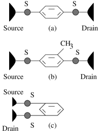
it is the so-called benzene-, -dithiolate molecule. The symmetry can be broken by adding a chemical substituent group at any one arm of the molecular ring (Fig. 2(b)) or by contacting the electrodes asymmetrically as given in Fig. 2(c), where the electrodes are connected at and positions (according to the clockwise direction). The idea of considering such different geometries is that only in this way the interference conditions are changed and they have strong influence on the electron transport through molecular bridges.
All the essential features of electron transport are discussed in the two distinct regimes. One is defined as , called the weak-coupling regime and the other one is mentioned as , called the strong-coupling regime, where and are the hopping strengths of the molecule to the source and drain,

respectively. Throughout the work, common set of values of the parameters used in our calculations for these two limiting cases are as follows: , (weak-coupling) and , (strong-coupling). The Fermi energy is fixed at .
Figure 3 shows the variation of conductance as a function of injecting electron energy for the single benzene molecules in the limit of weak-coupling, where (a), (c) and (e) correspond to the results for the models given in Figs. 2(a), (b) and (c), respectively. To observe different resonant and anti-resonant peaks much more clearly, in the nd column of Fig. 3 we plot the lower portions of the curves given in the st column of this figure. From the curves plotted in the column, it is observed that the conductance shows sharp resonant peaks for some particular energy values, while it vanishes for all other energies. At resonance, conductance

approaches to , and accordingly, the transmission probability becomes unity since we get the relation from the Landauer conductance formula (see Eq. 1 with in our present formulation). The resonant peaks in the conductance spectrum coincide with the eigenenergies of the single benzene molecules. Thus we can say that the conductance spectrum manifests itself the electronic structure of the molecules.
The effect of quantum interference becomes much more clear from the results plotted in Figs. 3(c) and (e). These results predict that some of the conductance peaks do not reach to unity anymore and get much reduced amplitude. This feature can be understood as follows. Electrons are transmitted through the molecule from source to drain. Electronic waves propagating along the two arms of the molecular ring acquire a phase shift among themselves, and therefore, the probability amplitude of getting an electron after traversing through the molecule becomes higher or smaller. It manifests itself especially as transmittance cancellations and provides anti-resonant states in the conductance spectrum. Thus, we can predict that the electronic transport is significantly influenced by the quantum interference effect i.e., the molecule- electrode interface structure.
The effect of molecular coupling has a significant role in electron transport. In the strong molecule-to-electrode coupling limit, all the resonant peaks get substantial widths, as shown in Fig. 4, where the solid, dotted and dashed curves correspond to the results for the molecular bridges presented in Figs. 2(a), (b) and (c), respectively. The enhancement of the resonance widths is due to the broadening of the molecular energy levels in the limit of strong molecular coupling, where the contribution comes from the imaginary parts of the self-energies and [35].
The other significant feature observed from the conductance spectrum is the appearance of anti-resonant states where the conductance vanishes exactly to zero. Such anti-resonant states are specific to the interferometric nature of the scattering and they do not appear in traditional one-dimensional scattering problems. It is also noticed that the positions of the anti-resonances on energy scale are independent of the molecule-to-electrode coupling strength which are clearly observed from the results plotted in the second column of Figs. 3 and 4. Since the widths of these states are very small they do not provide any significant contribution in the current-voltage characteristics. However, the variations of interference conditions have strong influence on the magnitude of current flowing through the molecular bridges.
The scenario of electron transfer through the molecular wires becomes much more clearly observed from the current-voltage (-) spectra. Current through the molecular system is computed by the integration method of the transmission function . The feature of the transmission function is exactly similar to that of the conductance spectrum, differ only in magnitude by a factor , according to the Landauer conductance formula . In Fig. 5, we display the current-voltage characteristics for the molecular bridges shown in Fig. 2,
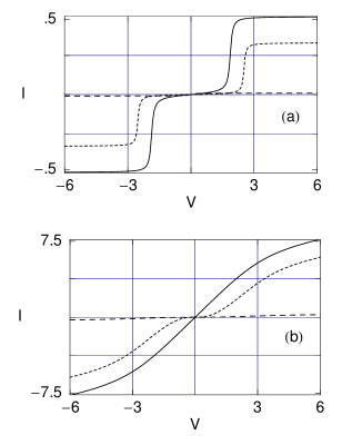
where (a) and (b) represent the currents for the weak- and strong-coupling limits, respectively. The solid, dotted and dashed lines correspond to the results for the molecular bridges given in Figs. 2(a), (b) and (c), respectively. It is observed that, in the limit of weak molecular coupling current shows staircase-like structure with sharp steps. This is due to the existence of discrete molecular resonances as shown in Fig. 3. With the increase in applied bias voltage , the difference in electrochemical potentials between the two electrodes increases, favoring more number of discrete energy levels to fall in that range, and therefore, more energy channels are accessible to the injected electrons to pass through the molecule from the source to drain. Incorporation of a single discrete energy level i.e., a discrete quantized conduction channel, between the range provides a jump in the - characteristics. The shape and height of these current steps depend on the width of the molecular resonances. With the increase of molecule-to-electrode coupling strength, current varies continuously as a function of the applied bias voltage and gets much higher values, as shown in Fig. 5(b). Both for the weak- and strong-coupling limits, current amplitude gets reduced for the asymmetric bridges (see the dotted and dashed curves), and for the bridge given in Fig. 2(c) current almost vanishes. This is solely due to the effect of quantum interference between the electronic waves passing through different arms of the molecular ring. Hence, it can be clearly emphasized that, designing a molecular device is strongly influenced by the molecule-to-electrode interface structure as well as molecular coupling strength.
3.2 Array of benzene molecules attached to electrodes
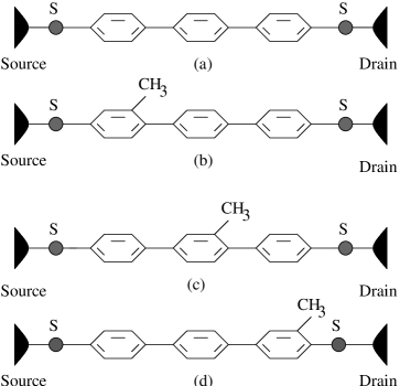
This section follows electron transport through an array of benzene molecules. Schematic representations for some array of benzene molecules are shown in Fig. 6, where the molecules are attached to the electrodes via thiol groups. Figure 6(a) represents the array of benzene molecules without any chemical substituent, while for the other three arrays the chemical substituent is added at different molecules as shown in Figs. 6(b), (c) and (d), respectively.
For these molecular bridges we also get the resonant and anti-resonant peaks (not plotted here) as a function of energy similar to the cases of single molecular bridge systems. Since the resonant peaks are associated with the eigenenergies of the molecule itself, here we get more resonant peaks compared to Figs. 3 and 4. Due to the breaking of molecular symmetry by adding the chemical substituent group , more anti-resonant peaks appear
for these molecular wires. In the weak-coupling limit, resonant peaks are very sharp, while in the strong molecular coupling they get broadened substantially.
The scenario of the current-voltage characteristics for these array of molecules is presented in Fig. 7, where (a) and (b) correspond to the results in the limits of weak- and strong-coupling, respectively. The solid, dotted, small dashed and dashed curves are, respectively, for the bridges presented in Figs. 6(a), (b), (c) and (d). Current shows sharp staircase-like behavior (see Fig. 7(a)) in the limit of weak-coupling associated with the discrete molecular energy levels. Here, more steps in the - curve appears than the single molecular bridge systems (see Fig. 5(a)). With the increase of molecular coupling, current varies almost continuously as given in Fig. 7(b)
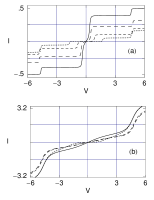
and achieves much higher values than the current observed in the weak molecular coupling. Finally, here we also like to mention that the current amplitude gets reduced with the addition of chemical substituent group irrespective of its position in the array.
3.3 Single benzene molecules attached to electrodes in presence of magnetic flux
At the end, here we study the behavior of conductance of the single benzene molecules given in Fig. 2 in the presence of transverse magnetic field . We assume that the transverse magnetic field passes through the molecular ring in such a way that it doesn’t penetrate the circumference of the ring

anywhere, and therefore, we neglect additional Zeeman term in our calculations. Due to the magnetic flux , associated with transverse magnetic field , an additional phase difference appears between the electronic waves traversing through different arms of the molecular ring, and accordingly, the tight-binding Hamiltonian (Eq. 5) gets modified by a phase factor. The single band tight-binding Hamiltonian that describes the molecule in the presence of a magnetic flux can be written within the non-interacting electron picture in the following form,
| (12) |
where, represents the phase factor due to the flux threaded by the molecular ring and other symbols carry their usual meaning as in Eq. 5. Introducing a magnetic flux, interference conditions can also be changed. Both constructive and destructive interferences take place, and therefore, the oscillating behavior of conductance with is observed. In Fig. 8, we plot - characteristics of single benzene molecules, where the st, nd and rd rows represent the results for the molecular models shown in Figs. 2(a), (b) and (c), respectively. The st column of Fig. 8 corresponds to the variation for the typical energy , while the nd column of this figure represents the variation when the energy is fixed at . The solid and dotted curves denote the results for the strong and weak molecule-to-electrode coupling limits, respectively. Conductance shows oscillatory behavior with exhibiting flux-quantum periodicity with extremas at half-integer flux quantum ( i.e., in our chosen unit) irrespective of the molecular coupling strength. In the weak-coupling limit, conductance almost vanishes (dotted curves) for all these three molecular bridges, while for the limit of strong-coupling they get much higher values (solid curves). Though in the presence of conductance () gets modified significantly compared to that in the absence of any , yet the current-voltage characteristics do not change appreciably. Thus, it can be emphasized that by applying such magnetic field, current cannot be modified significantly in these molecular bridge systems.
All the above pictures remain valid if the electron-electron interaction is taken into account. The main effect of the electron correlation is to shift and to split the resonant positions. This is due to the fact that the on-site Coulomb repulsive energy gives a renormalization of the site energies. Depending on the strength of the nearest-neighbor hopping integral () compared to the on-site Coulomb interaction () different regimes appear. For the case , the resonances and anti-resonances would split into two distinct narrow bands separated by the on-site Coulomb energy. On the other hand, for the case where , the resonances and anti-resonances would occur in pairs.
4 Concluding remarks
To conclude, we have introduced a parametric approach based on the tight-binding model to investigate the transport properties through benzene-, -dithiolate molecular model and some other geometric models of benzene molecule. Molecular geometry and molecule-to-electrode coupling strength have significant roles on the electronic transport through such molecular wires. Conductance shows resonant peaks for some particular energies associated with the molecular energy levels, while in all other cases it drops to zero. Due to breaking of the molecular symmetry more anti-resonant peaks appear in the conductance spectra and their positions are independent of the molecular coupling strength.
In the weak-coupling limit, current shows staircase-like structure, while it gets a continuous variation with the applied bias voltage in the limit of strong-coupling. For a fixed molecular coupling, current amplitude in symmetric molecule is quite higher than the asymmetric one, which is controlled by the quantum interference effect of the electronic waves passing through different arms of the molecular ring. It is also observed that for a particular molecular wire, current amplitude can be enhanced an order of magnitude by changing the molecular coupling strength.
Lastly, we have studied the behavior of conductance for the single benzene molecules in presence of the transverse magnetic field. Conductance shows oscillatory behavior with flux and gives flux-quantum periodicity. We have observed that the conductance changes in presence of magnetic field but the current-voltage characteristics remain same and thus we can predict that the current cannot be controlled significantly by means of such magnetic field in these molecular bridges.
In the present paper we have done all the calculations by ignoring the effects of the temperature, electron-electron correlation, etc. Due to these factors, any scattering process that appears in the molecular ring would have influence on electronic phases, and, in consequences can disturb the quantum interference effects. Here we have assumed that, in our sample all these effects are too small, and accordingly, we have neglected all these factors in this particular study.
Acknowledgments
It is a pleasure to thank Atikur Rahman (my best friend) and Prof. S. N. Karmakar for many helpful comments and suggestions.
References
- [1] A. Aviram and M. Ratner, Chem. Phys. Lett. 29, 277 (1974).
- [2] R. M. Metzger et al., J. Am. Chem. Soc. 119, 10455 (1997).
- [3] J. Chen, M. A. Reed, A. M. Rawlett and J. M. Tour, Science 286, 1550 (1999).
- [4] C. M. Fischer, M. Burghard, S. Roth and K. V. Klitzing, Appl. Phys. Lett. 66, 3331 (1995).
- [5] M. V. Fischetti, Phys. Rev. Lett. 53, 1755 (1984).
- [6] R. Baer and D. Neuhauser, Chem. Phys. 281, 353 (2002).
- [7] R. Baer and D. Neuhauser, J. Am. Chem. Soc. 124, 4200 (2002).
- [8] D. Walter, D. Neuhauser and R. Baer, Chem. Phys. 299, 139 (2004).
- [9] K. Walczak, Cent. Eur. J. Chem. 2, 524 (2004).
- [10] K. Walczak, Phys. Stat. Sol. (b) 241, 2555 (2004).
- [11] S. K. Maiti, Phys. Lett. A 373, 4470 (2009).
- [12] S. K. Maiti, J. Phys. Soc. Jpn. 78, 114602 (2009).
- [13] S. K. Maiti, Solid State Commun. 149, 1684 (2009).
- [14] S. K. Maiti, Solid State Commun. 149, 1623 (2009).
- [15] K. Tagami, L. Wang and M. Tsukada, Nano Lett. 4, 209 (2004).
- [16] M. A. Reed, C. Zhou, C. J. Muller, T. P. Burgin and J. M. Tour, Science 278, 252 (1997).
- [17] S. Hong, W. Tian, J. Henderson, S. Datta, C. P. Kubiak and R. Reifenberger, Superlat. Microstruct. 28, 289 (2000).
- [18] S. J. Tans, R. M. Verschueren and C. Dekker, Nature 393, 49 (1998).
- [19] M. Bockrath, D. H. Cobden, P. L. McEuen, N. G. Chopra, A. Zettl, A. Thess and R. E. Smalley, Science 275, 1922 (1997).
- [20] Z. J. Donhauser et al., Science 292, 2303 (2001).
- [21] X. D. Cui, A. Primak and X. Zarate et al., Science 294, 571 (2001).
- [22] J. H. Schon, H. Meng and Z. N. Bao, Science 294, 2138 (2001).
- [23] Molecular Electronics-Science and Technology, edited by A. Aviram and M. Ratner (N. Y. Acad. Sci., N. Y., 1998) (volume 852 of Ann. N. Y. Acad. Sci.).
- [24] S. Roth and C. Joachim, Atomic and Molecular Wires, Kluwer, Dordrecht (1997).
- [25] S. N. Yaliraki, A. E. Roitberg, C. Gonzalez, V. Mujica and M. A. Ratner, J. Chem. Phys. 111, 6997 (1999).
- [26] M. Di Ventra, S. T. Pantelides and N. D. Lang, Phys. Rev. Lett. 84, 979 (2000).
- [27] Y. Xue, S. Datta and M. A. Ratner, J. Chem. Phys. 115, 4292 (2001).
- [28] J. Taylor, H. Gou and J. Wang, Phys. Rev. B 63, 245407 (2001).
- [29] P. A. Derosa and J. M. Seminario, J. Phys. Chem. B 105, 471 (2001).
- [30] P. S. Damle, A. W. Ghosh and S. Datta, Phys. Rev. B 64, R201403 (2001).
- [31] V. Mujica, M. Kemp and M. A. Ratner, J. Chem. Phys. 101, 6849 (1994).
- [32] V. Mujica, M. Kemp, A. E. Roitberg and M. A. Ratner, J. Chem. Phys. 104, 7296 (1996).
- [33] M. P. Samanta, W. Tian, S. Datta, J. I. Henderson and C. P. Kubiak, Phys. Rev. B 53, R7626 (1996).
- [34] M. Hjort and S. Staftröm, Phys. Rev. B 62, 5245 (2000).
- [35] S. Datta, Electronic transport in mesoscopic systems, Cambridge University Press, Cambridge (1997).
- [36] W. Tian, S. Datta, S. Hong, R. Reifenberger, J. I. Henderson and C. I. Kubiak, J. Chem. Phys. 109, 2874 (1998).