Point-defect haloing in curved nematic films
Abstract
We investigate the correlation between the point disclination energies and the surface curvature modulation of nematic liquid crystal membranes with a Gaussian bump geometry. Due to the correlation, disclinations feel an attractive force that confines them to an annulus region, resulting in a halo distribution around the top of the bump. The halo formation is a direct consequence of the nonzero Gaussian curvature of the bump that affects preferable configurations of liquid crystal molecules around the disclination core.
pacs:
61.30.Jf, 61.30.Hn, 81.40.Lm, 02.40.-kI Introduction
It is generally assumed that topological defects in liquid crystal membranes are excluded in the ground state because they increase the elastic free energy of the system to more than that in the defect-free equilibrium state. The situation is quite different when the liquid crystal phases are embedded in a curved surface. In a curved membrane with nonzero Gaussian curvature, the appearance of topological defects can be favorable or even inevitable because of geometrical and/or topological constraints. A typical example is a disclination-containing equilibrium state in a nematic liquid crystal that is constrained in a spherical surface lubensky . The defect structure in such a nematic spherical shell has recently been reconsidered both theoretically nelson ; vitelli1 ; skacej ; shin and experimentally fernandeznieves ; lopezleon , and these investigations revealed richer physical properties than those that have initially been suggested. In addition to the nematic cases, the smectic phases of liquid crystal films xing ; gomez and columnar phases of a block copolymer assembly santangelo have also exhibited an interplay between disclination structures and the geometry/topology of the constraint surface. In particular, smectic ordering on a sinusoidal substrate has indicated a direct coupling between the substrate curvature and the preferential locations of disclinations in equilibrium states gomez . The coupling is purely a geometric curvature effect in the sense that the system involves no topological requirement for the existence of disclination. The geometric curvature also strongly influences the orientational order of the spin lattice models defined on curved surfaces shima1 ; shima2 ; dandoloff ; isaku ; baek1 ; carvalhosantos ; baek2 ; sakaniwa .
Many intriguing results have been obtained with regard to the global lowest-energy state on a curved surface with a minimum number of disclinations, which should be relevant to liquid crystal phases at very low temperatures. In actual systems, however, a slight physical (and chemical) disturbance causes excess disclinations degennes ; mermin ; romanov ; kleman . These disclinations can travel over a surface via thermal excitation, and they flow almost freely if the disclination density is sufficiently low to ignore their interaction. The only possible force that restricts the free motion of the excess disclinations arises from a coupling between the surface curvature and the disclination energy. The substrate curvature breaks the translational symmetry of the molecular configuration in the vicinity of the disclination core, which may cause a shift in the disclination energy. As a result, the energetically preferential positions of excess disclinations are believed to be tunable by imposing an appropriate curvature modulation.
In this article, we study the energies of disclinations in a nematic thin film assigned on a Gaussian bump. It is found that disclinations with a charge prefer positioning at inflection points of the bump, implying the formation of a “halo,”i.e., an annulus distribution of excess disclinations around the top of the bump. In addition, disclinations with a charge are found to exhibit double concentric halo structures, provided the bump height is relatively large. These halo formations are consequences of the non-trivial coupling between the disclination energies and the surface curvature modulation.
II Model
We consider nematic liquid crystals confined in a thin curved membrane with thickness , in which the molecules align parallel to the tangential directions independently of the depth in the membrane. In line with the continuum theory young ; degennes , the elastic free energy of the molecular ensemble within the volume is given by
| (1) |
where the unit vector (called the director field) describes the local molecular alignment. is a vector operator whose components are the covariant derivative shima3 on the curved surface. and are the elastic constants associated with splay and bend distortions of the molecular configuration, respectively stewart .
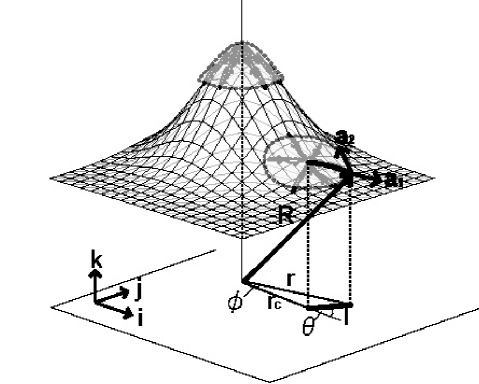
Suppose that the director lies within a thin curved shell having a Gaussian bump geometry. Points on the bump are represented by a three-dimensional vector given by
| (2) |
where , , and are basis vectors of the Cartesian coordinate system, and and are the polar coordinates assigned on the underlying flat plane (see Fig.1). The geometric deviation of a bump from a flat plane is characterized by a dimensionless parameter that represents the ratio of the height to the width of the bump. Note that the constant in the last term in Eq.(2) determines the points of inflection of the Gaussian bump, i.e., across which the sign of changes. We demonstrate below that plays a prominent role in describing the correlation between the disclination energy and the substrate curvature.
Let us locate a disclination core on a point , where is an arbitrary constant without loss of generality. The disclination size is sufficiently smaller than the bump width, and the perimeter of the disclination is defined by the locus of points whose distances from the core are equal in the sense of geodesic distance; therefore, the perimeter slightly deviates from a circular shape when it is placed on a curved surface, whereas it is an exact circle when placed on a flat plane.
For later use, we introduce a new polar coordinate system on the flat plane such that the coordinate origin (i.e., ) locates at the point of interaction of the flat plane and the vertical line penetrating the disclination core (see Fig.1). Then, the basis vectors and span the curved surface and allow us to write (), where and depend on and (See Appendix B). The director orientation around the core is given by the angle between and . It is natural to assume that
| (3) |
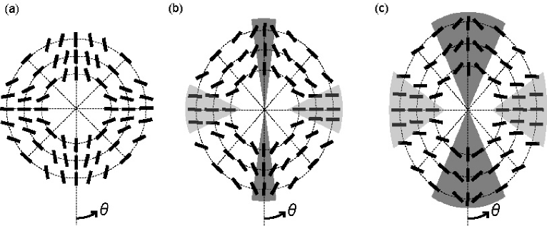
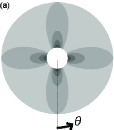
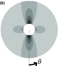
where denotes the disclination charge that quantifies how many times rotates about the core. When , for instance, all contained within the disclination area make the same angle with respect to (see Fig.3(a)); on the other hand, when , the angle increases proportionally to (see Fig.4(a)).
In the calculation, we consider disclinations with two charges, . The disclination area and the membrane thickness are set to be and by referring to the material constants of actual liquid crystal membranes shah . The values of the elastic constants and are those of 4-methoxybenzylidene-4′-butylaniline (MBBA), p-azoxyanisole (PAA), and 4-pentyl-4′-cyanobiphenyl (5CB) presented in Table 1 stewart . The constant in Eq.(3) is fixed to be zero without loss of generality, bearing in mind the fact that other choices of lead to no essential change in the conclusion of this work.
| Elastic constants | MBBA | PAA | 5CB |
|---|---|---|---|
| (pN) | (C) | (C) | (C) |
| 6 | 6.9 | 6.2 | |
| 7.5 | 11.9 | 8.2 |
III Result
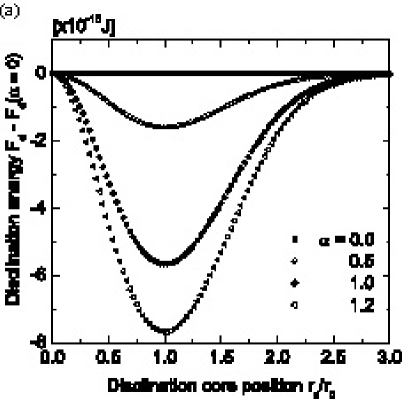
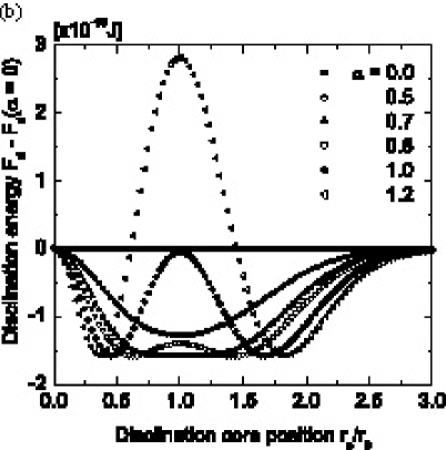
Figure 2 shows plots of the disclination energy of MBBA as a function of the core position . The vertical axis shows the difference in between the bump and the flat plane, i.e., . The disclination charge is in (a) and in (b), and the parameter ranges from to in both (a) and (b). For , takes the minimum at for all values of , indicating that a disclination is stable at the inflection point of the bump independently of the bump height. On the other hand, the plot for exhibits a transition from a single downward peak structure () into a double-well structure () such that becomes unstable. The contrasting behaviors of for and are attributed to surface curvature effects on the director configuration close to the core, as will be shown in Sec.IV. For PAA and 5CB, we have obtained similar profiles of exhibiting a downward peak at for and a double-well structure for , whereas the peak heights differ slightly from those shown in Fig.2 because of quantitative differences in and . We have also confirmed that the peak positions (both downward and upward) are independent of our choice of defined by Eq.(3).
We emphasize that the energy scales of the potential wells shown in Figs.3(a) and 3(b) exceed the thermal energy scale at ambient temperature. For instance, the depth of the single well for and given in Fig.3(a) is approximately ; this is of the order of at . This fact suggests that the potential well at overwhelms the thermal excitation that causes a random movement of disclinations over the surface. As a result, an ensemble of trapped disclinations forms a halo with radius around the top of the Gaussian bump, provided that the disclination density is sufficiently low to ignore their repulsive interaction. The same scenario applies to disclinations with a charge of , implying the formation of doubly consentric halos observed for .

IV Discussions
The physical origin of a downward peak in the plot of for (see Fig.2(a)) is a curvature-induced shift in the director configuration around the disclination core. Figures 3(a) and 3(b) illustrate how the configuration varies with a shift in the core position from (a) to (b). In Fig.3(a), aligns radially around the top of the bump, exhibiting rotational symmetry such that and at every point. This symmetry breaks down for . By increasing , the perimeter of the disclination distorts slightly and becomes elliptical, and then, the relationship no longer holds (see Fig.3(b)), except along the four specific line segments (). The most important observation in Fig.3(b) is a suppression of the splay deformation in the shadowed region. The area of the corresponding region is maximized at , as a result of which a downward peak arises at at the expense of a slight splay enhancement within a limited region around .
Parallel arguments to the preceding paragraph account for the double-well structure of for that is shown in Fig.2(b). Figures 4(a)–(c) show the variation of the configuration under and , each figure corresponding to the core position: (a), (b), and (c). The director configuration in (a) exhibits a four-fold rotational symmetry that breaks down as increases. Symmetry breaking induces a suppression of the splay deformation in the light-shadowed regions shown in Fig.4(b) and 4(c) in a manner similar to the case of . In contrast, the splay deformation in the dark-shadowed regions is enhanced with an increase in . These two competing effects result in the double-well structure of for cases. That is, decreases with when the suppression effect exceeds the enhancement, and it increases in the opposite situation. The degree of splay enhancement in the dark regions is maximized at ; this explains why is the most unstable point for disclinations.
We have numerically confirmed that the splay term in Eq.(1) plays a dominant role in describing the - (and -) dependences of . Figures 5(a)–(b) show contour plots of the splay term within the disclination area of . We observe that with an increase in , the local splay energy decreases at points near but increases near ; this is in agreement with our previous discussions. A more detailed version of the study that covers the variations of the disclination size and the initial angle will be presented elsewhere.
V Summary
In conclusion, we investigated the elastic energy of disclinations that arise in a curved nematic membrane with a Gaussian bump geometry. When , the disclination energy exhibits a downward peak at independently of the sign of the disclination charge, suggesting a curvature-driven halo formation of disclinations around the top of the bump. Furthermore, when , for exhibits a double-well structure in which the point becomes unstable in contrast to the case of ; this implies doubly concentric halos peculiar to negatively charged disclinations. In both cases of , the well depth overcomes the thermal energy scale at room temperature, suggesting the experimental feasibility of our theoretical predictions.
Acknowledgements
We would like to thank for K. Yakubo and H. Orihara for the fruitful discussions. IH is thankful for the financial support from the 21st Century COE Program “Topological Science and Technology”and support from the Japan Society for the Promotion of Science for Young scientists. HS acknowledges M. Arroyo for assisting with the work carried out of UPC. This work is supported by the Kazima foundation and a Grant-in-Aid for Scientific Research from the Japan Ministry of Education, Science, Sports and Culture.
Appendix A Metric tensor
In this Appendix, we derive the metric tensor in terms of the covariant basis vectors and introduced in Sec. II. We start with the basis vectors and associated with the polar coordinate system on the flat plane. In terms of and , the metric tensor becomes
| (6) |
We use a coordinate transformation from to by shifting the coordinate origin from to . This is accomplished by multiplying both sides of by the Jacobian defined by
| (9) |
whose elements can be computed by using the following relationships: and . Finally we obtain
| (10) | |||||
| (14) |
where and . In particular, when (i.e., a flat plane), , and thus, we have
| (15) |
as expected.
Appendix B Contravariant components
We present the derivation of the contravariant component of the vector in terms of . First, the relative angle between and is denoted as . Similarly, the angle between and is denoted as . It follows from Eq.(14) that
| (16) | |||||
| (17) |
where . We thus have
| (18) |
which leads us to the explicit forms of the covariant components such as
| (19) | |||||
| (21) | |||||
| (22) |
Finally, the formulas with is employed to obtain
| (23) | |||||
| (24) |
References
- (1) T. C. Lubensky and J. Prost, J. Phys. II France 2, 371 (1992).
- (2) D. R. Nelson, Nano Lett. 2,1125 (2002).
- (3) V. Vitelli and D. R. Nelson, Phys. Rev. E 74, 021711 (2006).
- (4) G. Skačej and C. Zannoni, Phys. Rev. Lett. 100, 197802 (2008).
- (5) H. Shin, M. J. Bowick and X. Xing, Phys. Rev. Lett. 101, 037802 (2008).
- (6) A. Fernández-Nieves, V. Vitelli, A. S. Utada, D. R. Link, M. Márquez, D. R. Nelson and D. A. Weitz, Phys. Rev. Lett. 99, 157801 (2007).
- (7) T. Lopez-Leon and A. Fernandez-Nieves, Phys. Rev. E 79, 021707 (2009).
- (8) X. Xing, Phys. Rev. Lett. 101, 147801 (2008).
- (9) L. R. Gómez and D. A. Vega, Phys. Rev. E 79, 031701 (2009).
- (10) C. D. Santangelo, V. Vitelli, R. D. Kamien and D. R. Nelson, Phys. Rev. Lett. 99, 017801 (2007).
- (11) H. Shima and Y. Sakaniwa, J. Phys. A: Mech. Gen. 39, 4921 (2006).
- (12) H. Shima and Y. Sakaniwa, J. Stat. Mech. (2006) P08017.
- (13) R. Dandoloff and A. Saxena, Phys. Lett. A 358, 421 (2006).
- (14) I. Hasegawa, Y. Sakaniwa and H. Shima, Surf. Sci. 601, 5232 (2007).
- (15) S. K. Baek, P. Minnhagen and B. J. Kim, Europhys. Lett. 79, 26002 (2007).
- (16) V. L. Carvalho-Santos, A. R. Moura, W. A. Moura-Melo and A. R. Pereira, Phys. Rev. B 77, 134450 (2008).
- (17) S. K. Baek, P. Minnhagen and B. J. Kim, Phys. Rev. E 79, 011124 (2009).
- (18) Y. Sakaniwa and H. Shima, Phys. Rev. E 80, 021103 (2009).
- (19) P. G. de Gennes, The Physics of Liquid Crystals (Clarendon Press, Oxford, 1974).
- (20) N. D. Mermin, Rev. Mod. Phys. 51, 591 (1979).
- (21) A. E. Romanov, Eur. J. Mech. A-Solid 22, 727 (2003).
- (22) M. Kleman and J. Freidel, Rev. Mod. Phys. 80, 61 (2008).
- (23) C. Y. Young, R. Pindak, N. A. Clark and R. B. Meyer, Phys. Rev. Lett. 40, 773 (1978).
- (24) H. Shima and T. Nakayama, Higher Mathematics for Physics and Engineering (Springer-Verlag, 2010), in press.
- (25) I. W. Stewart, The Static and Dynamic Continuum Theory of Liquid Crystals (Taylor & Francis, London and New York, 2004).
- (26) R. R. Shah and N. L. Abbott, J. Phys. Chem. B 105, 4936 (2001).