Diverse corrugation pattern in radially shrinking carbon nanotubes
Abstract
Stable cross-sections of multi-walled carbon nanotubes subjected to electron-beam irradiation are investigated in the realm of the continuum mechanics approximation. The self-healing nature of sp2 graphitic sheets implies that selective irradiation of the outermost walls causes their radial shrinkage with the remaining inner walls undamaged. The shrinking walls exert high pressure on the interior part of nanotubes, yielding a wide variety of radial corrugation patterns (i.e., circumferentially wrinkling structures) in the cross section. All corrugation patterns can be classified into two deformation phases for which the corrugation amplitudes of the innermost wall differ significantly.
pacs:
61.46.Fg, 46.70.De, 62.50.-p, 61.80.AzI Introduction
Carbon nanotubes exhibit remarkable flexibility when subjected to cross-sectional deformation. Despres1995 ; Iijima1996 ; Palaci2005 Such flexibility has been evidenced by spectroscopy and diffraction measurements in which hydrostatic pressure on the order of a few GPa caused flattening and polygonization in the cross section. Peters2000 ; J_Tang2000 ; Elliott2004 Molecular-dynamics (MD) Tangney2005 ; Gadagkar2006 ; Zhang2006 and density-functional-theory-based simulationsReich2002 ; Chan2003 revealed more details about the mechanism of radial deformation under pressure. Radial deformation can also be caused by a nanoindentation Barboza_2008 under which the elastic response of single-walled nanotubes (SWNTs) is determined by a universal law that depends on the tube radius and applied load.Barboza_2009 As the radial deformation of nanotubes is strongly correlated with their electronic Barboza_2008 ; Park1999 ; Mazzoni2000 ; Gomez2006 and optical Lebedkin2006 properties, its clarification should be important from the viewpoint of the use of nanotubes as components of nanoscale devices.
The cross section of an isolated SWNT exhibits a circular-to-elliptic transition at a critical hydrostatic pressure . The value of decreases with as Yakobson1996 ; DYSun2004 , which agrees with the conclusion of the classical continuum theory. Brush_1975 This scenario, however, fails in the case of multi-walled nanotubes (MWNTs). It has been shown that MWNTs consisting of several tens of concentric walls undergo a novel cross-sectional deformation, called radial corrugation, NTN in which the outer walls exhibit wavy structures along the circumferential direction. The radial corrugation originates from the multilayered nature, i.e., the competing effects between the mechanical instability of outer walls with large radii and the radial rigidity of inner walls with small radii.
The corrugation behavior of a MWNT is believed to change if it occurs in an embedding elastic medium. Suppose that a MWNT is embedded in a large elastic medium that is in complete contact with its outermost wall. A uniform shrinkage of the medium exerts an external force on the outermost wall, as similar to the case of hydrostatic pressure. But a difference arises when the medium possesses moderate stiffness, since the energy required to deform the medium should be responsible for determining the stable corrugation pattern. In fact, when a thin flat plate is embedded in an elastic medium and comressed, it shows a uni-directional corrugation whose profile is strongly dependent on the medium’s stiffness.Allen_1969 ; Volynskii_2000 This fact implies an uncovered corrugation mechanism peculiar to embedded MWNTs, it i.e., dinstinct from the hydrostatic pressure cases, which imposes new challenges.
In this article, we demonstrate that the presence of a surrounding elastic medium triggers diverse variations of corrugation modes that cannot be observed in MWNTs under hydrostatic pressure. These diverse modes are found to be grouped into two corrugation phases that exhibit a significant difference in the corrugation amplitude of the innermost wall of the MWNT. These findings will help to tune the core-tube geometry of MWNTs, thus providing useful information for developing nanofluidic Majumder2005 ; Noy2007 ; Whitby2007 or nanoelectrochemical Frackowiak2001 devices whose performance depends on the geometry of the inner hollow cavity of nanotubes.
II Methodology
II.1 Self-healing nature of graphite sheets
The current work has been inspired by the discovery of the self-healing properties of carbon nanostructures under electron-beam irradiation.Banhart1996 ; Ajayan1998 ; Banhart2005 ; LSun2006 ; Krasheninnikov2007 Banhart et al. Banhart1996 found that carbon onions, assemblies of concentric spherical carbon shells, shrink toward smaller onion structures when irradiated. This shrinkage is attributed to the knock-on collision of carbon atoms from constituent shells; the resulting vacancies are healed by annealing reconstruction Ding2007 that shrinks the system with reduced intershell spacings. As a result, extreme pressure arises in the core of spherical carbon shells. Using a similar irradiation technique, Sun et al. LSun2006 synthesized MWNTs with reduced interwall spacing and revealed high pressures of several tens GPa within the hollow cavity. It is thus expected that self-contraction of only outermost walls of a MWNT (possibly realized by finely-focused beam) will provide the setting for radial corrugation of the interior part of the MWNT.
It should be borne in mind that in the carbon onion experiments, diamond nucleation occurs at the center of the onion as the induced pressure is too high for the original sp2 bonds to persist.Banhart1996 To make the current work convincing, therefore, it is important to examine whether the critical pressure for the corrugation is low enough to prevent the breaking of sp2 bonds within the inner walls. We will revisit this issue in Section III B.
II.2 Continuum model of radially shrinking MWNT
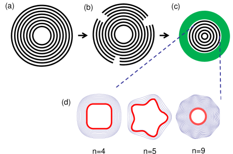
When treating many-walled nanotubes, atomistic simulations are realistic and accurate but they demand huge computational cost in general. Thus we used a simplified model based on the continuum approximation. Yakobson1996 ; Ru ; Pantano2004 ; Huang First, we map an MWNT onto concentric cylindrical shells endowed with Kudin_PRB2001 the in-plane stiffness nN/nm, the flexural rigidity nNnm, and Poisson’s ratio , in which the inter-shell separation is defined by 0.3415 nm. Figures 1(a)-(c) illustrate the shrinking process considered in this paper. We assume an -walled nanotube under irradiation that kicks off a portion of carbon atoms located within outer walls surrounding inner walls. Then, self-contraction of the walls results in high pressure that exerts on the walls that they encapsulate. For the sake of analytical arguments, we simplify the walls by a continuum elastic medium and assume the outermost boundary of the -walled tube to be in contact with the inner surface of the medium throughout the shrinking process (see Figs. 1(b) and (c)). As a consequence, various corrugation patterns arise in the cross section of the -walled nanotube. Only a few examples of the corrugation patterns are shown in Fig. 1(d) together with the associated mode index representing the wave number in the circumferential direction.
It is noteworthy that the mechanical Xu ; Yang2009 and structural Guo consequences of irradiation in few-walled nanotubes have already been explored by atomistic simulations. Xu et al. numerically reproduced the irradiation-induced high pressure within a double-walled nanotubeXu ; they artificially removed carbon atoms from the outer wall and observed the subsequent self-healing process that causes an extreme pressure acting on the inner wall. A similar healing process is assumed to occur when the outer walls of a many-walled nanotube are eroded locally, as shown in Fig. 1(b). It should be noted that in the existing experiment, it is possible to remove carbon atoms from an MWNT with monolayer precision.JLi_2004 This fact supports the validity of our hypothesis that a part of the carbon atoms within only a desired number of outermost walls is removed locally.
II.3 Energy formulation
The stable cross-sectional shape of the embedded tube is obtained by minimizing its mechanical energy per unit axial length,NTN
| (1) |
The first term with the definition
| (2) |
represents the deformation energy; and are, respectively, in-plane and bending-induced strains of the th wall having the radius and is a circumferential coordinate. The second term in Eq. (1) with accounts for the van der Waals (vdW) interaction energy of all adjacent pairs of walls. Here, is the radial displacement of the th wall, and the coefficients are derived through a harmonic approximation of the vdW force WBLu_APL2009 accociated with the vdW potential with Girifalco_PRB2000 meV and =0.3415 nm. The final term in Eq. (1) is the negative of the work done by during cross-sectional deformation. It can be proved thatNTN all the three terms are functions of and the circumferential displacement of the th wall under .
The remaining term in Eq. (1) is the elastic energy of the surrounding medium. To derive it, we assume that the medium is homogeneous and isotropic with Young’s modulus GPa (that corresponds to the modulus of amorphous carbonOkada_2006 ; Champi_2008 ) and Poisson’s ratio . In polar coordinates, the radial and circumferential components of normal stress in the medium are denoted by and , respectively, and the shear stress is denoted by ; all the three quantities are functions of . Then, is determined by and at as
| (3) | |||||
| (4) | |||||
| (5) |
where and describe the corrugation amplitudes of the outermost wall of the embedded MWNT; see Eq. (6). The superscripts and indicate that the quantities correspond to a uniform contraction and radial corrugation, respectively. In plane words, represents the energy required for uniform radial contraction of the MWNT remaining in contact with the medium, and does for radial corrugation with the mode index . Details of the derivation of are presented in Appendix A.
II.4 Corrugation mode analysis
Our objectives are to determine: (i) the optimal displacements and that minimize under a given value of , and (ii) the critical pressure above which the circular cross section of an MWNT is elastically deformed into a non-circular one. These are accomplished by the decomposition , where describes a uniform radial contraction at and describes a deformed (non-circular) cross section observed immediately above . Similarly, we can write , because at . Applying the variation method to followed by the Fourier series expansions
| (6) |
we obtain the matrix equationNTN ; the vector consists of and with all possible and and the matrix involves one variable and other material parameters. Finally, we solve the secular equation with respect to to obtain a sequence of discrete values of among which the minimum one serves as the critical pressure . Immediately above , the circular cross section of MWNTs becomes radially deformed, as described by
| (7) | |||||
| (8) |
where the value of is uniquely determined by the one-to-one relationship between and .
We restrict our attention to the elastic limit (i.e., and be infinitesimally small); hence, neither delamination nor strong stacking effects are considered in the subsequent arguments, although these effects may change the corrugation patterns..
III Results
III.1 Cross-sectional view
Figure 1(d) illustrates a cross-sectional view of typical deformation modes: the two left-hand-side panels show “inward-deformation” modes with radial-corrugation mode indexes and , and the right-hand-side panel shows an “outward-deformation” mode with . In the inward-deformation mode, the innermost walls exhibit significant corrugation amplitudes as compared to the outside walls. Conversely, in the outward-deformation mode, the innermost wall maintains its circular shape. Which class of modes is observed immediately above depends on the values of the innermost tube radius and under consideration. As shown below, larger and smaller favor the inward mode with larger .
III.2 Critical pressure for radial corrugations
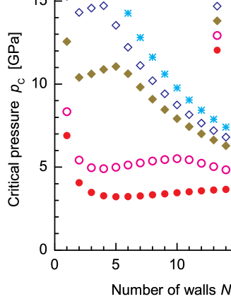
Figure 2 (a) shows the -dependence of for various conditions of . For all s, exhibits two shallow peaks (one upward and one downward) whose positions shift to larger with an increase in . One might expect that a larger leads to a larger , because an increase in the concentric walls would enhance the radial rigidity. This conjecture holds for MWNTs with intermediate values of between the two shallow peaks; for instance, for nm increases slowly with between and . However, to the right of the upward peak, decreases monotonically with , in contrast to the conjecture above. Such decay of at large arises from the mechanical instability of outside walls whose radii grow with , implying the occurrence of outward-deformation modes at large .
It also follows from Fig. 2(a) that a large portion of ’s data lies on the order of several GPa, though they occasionally exceed ten GPa or more at certain limited conditions. In the latter conditions, the continuum shell approximation may break down due to interwall sp3/sp2 hybridization bonds generated by pressure. In fact, earlier MD simulations Guo suggested that radial pressure of approximately 40 GPa (or 30 GPa) destroys the tubular structure of an encapsulated SWNT having the radius nm ( 1.2 nm) through the formation of hybrid sp2/sp3 self linkages inside the tube. It is thus conjectured that similar hybrid bonds between neighboring walls in MWNTs for nm occurs above a threshold pressure comparable to (or maybe less than) tens GPa. Precise determination of the threshold requires atomistic calculations; hence we proceed arguments bearing in mind that the obtained results are physically relevant only when is lower than the threshold (more or less tens GPa) that remains to be determined.
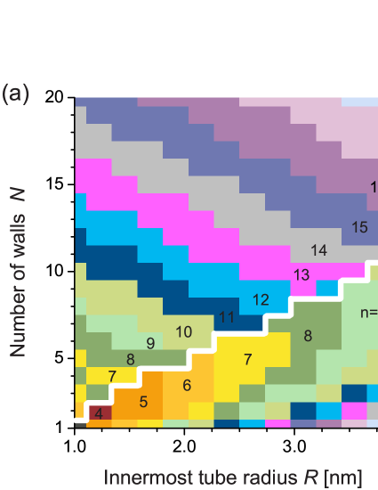
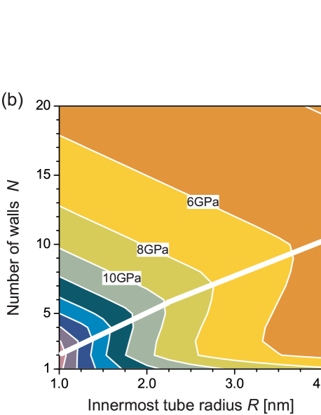
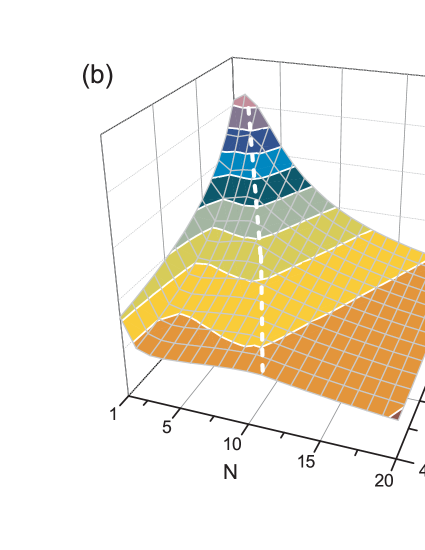
Figure 2(b) shows the three-dimensional plot on the - plane. The plot exhibits a ridge line that extends from the top at to the skirt at of the -surface. The ridge line corresponds to a phase boundary that separates the inward- and outward-deformation phases. In fact, an inward-deformation mode occurs in the region to the left of the ridge line, as we will find in the phase diagram in Fig. 3 (a).
III.3 Phase diagram
Figure 3(a) shows a phase diagram of the radial corrugation modes in MWNTs observed above . A stepwise bright line represents the phase boundary between the inward-deformation phase (below the line) and the outward phase (above). Figure 3(b) shows a contour plot of that evidences a strong correlation between the ridge line of (i.e., the solid slanted line in Fig. 3(b)) and the phase boundary shown in Fig. 3(a).
A salient feature of Fig. 3(a) is the absence of an elliptic deformation phase () within the ranges of and we have considered. The absence of the mode is in contrast with the cases of MWNTs and SWNTs under hydrostatic pressure; in fact, the mode in the latter two cases is the primary mode observed in a large domain of the - space. Furthermore, we have obtained a wide variety of corrugation modes for various values of and , where the variation of is systematic with the changes in and . In the inward-deformation phase, for instance, larger and smaller favor corrugation modes with large . Contrariwise, in the outward phase, smaller and larger favor corrugation modes with large .
III.4 Corrugation amplitudes
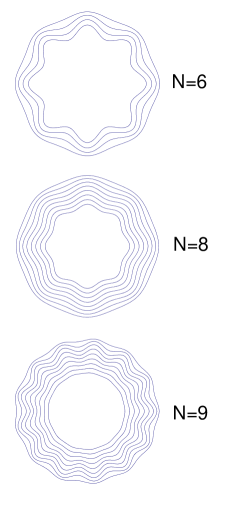
The contrasting difference in corrugation amplitude distributions between the inward and outward phases is quantified by plotting the deformation amplitudes introduced in Eq. (7). Figure 4 shows the normalized deformation amplitudes, , of individual concentric walls for -walled nanotubes with different and nm be fixed. It follows from the figure that the value of suddenly drops off from to across the phase boundary (i.e., from to with nm being fixed). To understand this visually, we show in Fig. 5 the sequential variation of the corrugation amplitude distribution in the cross section near the phase boundary, In the inward mode (), the restoring force exerted by the surrounding medium is relatively strong so that it tends to prevent radial deformation of outer walls; this is why inner walls exhibit significant corrugation amplitudes to lower the energy of the system. By increasing , such restoring force effects become ineffective to support the radial instability of outer walls, as a result of which the system falls into the outward phase for . A similar scenario applies if we fix and modulate in the vicinity of the phase boundary.
IV Discussions
The present results are based on the approximation that the radially shrinking part of an MWNT under electron-beam irradiation is mapped onto a continuum elastic medium with homogeneous and isotropic elasticity of the modulus GPa. The validity of the homogeneity and isotropy hypothesis depends on the following two effects of irradiation on the mechanical stiffness of MWNTs: irradiation reduces the axial stiffness because it creates vacancies,Sammalkorpi2004 ; Pigno2007 and simultaneously, it enhances the radial stiffness owing to the production of covalent bonding between adjacent walls.Krasheninnikov2007 A quantitative examination of the degree to which this hypothesis holds requires elaborated measurements or large-scale atomistic simulations, and therefore, we have no available data for the proof. Instead, it is possible to generalize the theoretical method by considering the possible anisotropic elasticity in the medium. Our preliminary calculations showed that moderate anisotropy causes little modification in the phase diagram. More detailed results will be shown elsewhere.
We have also performed corrugation analyses by imposing other values of than GPa. It was found that larger (smaller) values of result in more (less) number of corrugation modes observed in the phase diagram with fixed ranges of and set in Fig. 3(a). With decreasing , the phase boundary shifts downward until GPa, below which the boundary disappears leaving the outward phase as the only possibility. Therefore, our predictions of diverse corrugation patterns and the two corrugation phases are possible for any choice of as far as GPa.
From an engineering perspective, the selectivity of the innermost wall geometry by tuning the material parameters , and may be useful in developing nanotube-based nanofluidic Majumder2005 ; Noy2007 ; Whitby2007 or nanoelectrochemical devices Frackowiak2001 , because both utilize the hollow cavity within the innermost tube. A very interesting issue from the academic viewpoint is the effect of the core tube deformation on the physical and chemical properties of intercalated molecules confined in the hollow cavity. It has thus far been known that various types of intercalated molecules (diatomic gas, water, organic, and transition metal molecules, etc.) can fill the innermost hollow cavities of nanotubes Noy2007 and exhibit intriguing behaviors that are distinct from those of the corresponding bulk systems.Yang2003 ; Maniwa2007 These distinct behaviors originate from the fact that the intermolecular spacings become comparable to the linear dimension of the nanoscale confining space. Therefore, the core tube deformation that breaks the cylindrical symmetry of the initial nanoscale compartment will engender unique properties of intercalated molecules that are peculiar to the constrained condition in a radially corrugated space.

Another interesting implication of our results is a pressure-driven change in the quantum transport properties of -electrons moving along the radially corrugated nanotube. It has been known that mobile electrons whose motion is confined to a two-dimensional curved thin layer behave differently from those on a conventional flat plane, because the geometric curvature of the layer effectively yields an electromagnetic field ShimaPRB ; Ono ; Taira that can affect low-energy excitations of the electrons. A quantitative examination along with sophisticated atomistic simulations Arias should reveal novel MWNT applications based on radial corrugation.
V Conclusion
We have theoretically shown the presence of diverse radial corrugation modes in the cross section of MWNTs that shrink radially under irradiation. Using the continuum elastic approximation, we have established a phase diagram that enables a desired corrugation pattern to be obtained by tuning the innermost wall radius and the total number of concentric walls . We have also found that all corrugation patterns are classified into two deformation phases between which there exists a significant difference in the corrugation amplitude of the innermost wall of the nanotube. We believe that the results provide useful information for developing carbon-nanotube-based devices that utilize the nanoscale hollow cavity within the core of concentric carbon walls.
Acknowledgement
We acknowledge M. Rahimi, K. Yakubo and T. Mikami for stimulating discussions and helpful comments. This study was supported by a Grant-in-Aid for Scientific Research from the MEXT, Japan. HS is thankful for the financial support provided by the Kazima Foundation and Hokkaido Gas Co., Ltd. SG acknowledges the support of the Spanish Ministry of Science and Innovation through the Juan de la Cierva program. MA acknowledges the support of the European Research Council (FP7/2007-2013)/ERC grant agreement nr 240487 and the prize “ICREA Academia” funded by the Generalitat de Catalunya. A part of the numerical simulations were carried out using the facilities of the Supercomputer Center, ISSP, University of Tokyo.
Appendix A Derivation of
In this Appendix, we derive the deformation energy of an elastic medium surrounding a MWNT. The mechanics of an elastic medium is governed by the stress function that satisfies the so-called compatibility equationTimoshenko
| (9) |
where and . Once is obtained, we can deduce the radial and circumferential components of the normal stress, and , respectively, and the shear stress as follows.
| (10) | |||||
| (11) |
By definition, the strain components are given by the matrix form
| (12) |
where and are respectively the radial and circumferential displacements of a volume element in the host medium.
The general solution of Eq. (9) is given by , where andCroll
| (13) | |||||
| (14) | |||||
| (15) |
with similar definitions of . The zeroth component represents a uniform contraction of the circular cross section, thus corresponding to the energy that we have introduced in Eq. (4). The first one implies a rigid body translation that is irrelevant to our consideration. Other components for describe radial corrugations with mode index , thus providing the energy given by Eq. (5). In the following, we set and instead of Eqs. (13) and (15), respectively, in order to obtain physically relevant solutions of that decay with increasing .Croll
We now evaluate the explicit forms of and . To derive , we consider a specific solution of (9) that has the form of , and then substitute it in Eqs. (10) and (11) to obtain , , and . Hence, it follows from Eq. (12) that , . Complete contact between the medium and the outermost wall implies , and the elastic nature of the medium implies with the stiffness coefficient . Obviously, is identified with associated with the unit radial displacement . Hence, imposing an appropriate value of , we obtain . Moreover, the uniform contraction energy should be represented as . Consequently, we obtain the explicit form of that depends on and .
Next, we consider the energy that corresponds to the radial corrugation of the th order. We only consider the cosine term in without loss of generality, which is based on our assumption of cosine radial displacement (see Eq. (6)). A similar procedure to the case of yields
| (18) |
leading to the results
| (19) | |||||
| (20) | |||||
Parallel discussions to the case together with the formula
| (21) | |||||
| (22) |
lead us to attain the stiffness coefficients and as
| (23) | |||||
| (24) |
and , . Substituting the results (21)-(24) into Eq. (5), we finally obtain the explicit form of .
References
- (1) J. F. Despres, E. Daguerre, and K. Lafdi, Carbon 33, 87 (1995).
- (2) S. Iijima, C. Brabec, A. Maiti, and J. Bernholc, J. Chem. Phys. 104, 2089 (1996).
- (3) I. Palaci, S. Fedrigo, H. Brune, C. Klinke, M. Chen, and E. Riedo, Phys. Rev. Lett. 94, 175502 (2005).
- (4) J. Tang, L. C. Qin, T. Sasaki, M. Yudasaka, A. Matsushita, and S. Iijima, Phys. Rev. Lett. 85, 1887 (2000).
- (5) M. J. Peters, L. E. McNeil, J. P. Lu, and D. Kahn, Phys. Rev. B 61, 5939 (2000).
- (6) J. A. Elliott, J. K. W. Sandler, A. H. Windle, R. J. Young, and M. S. P. Shaffer, Phys. Rev. Lett. 92, 095501 (2004).
- (7) P. Tangney, R. B. Capaz, C. D. Spataru, M. L. Cohen, and S. G. Louie, Nano Lett. 5, 2268 (2005).
- (8) V Gadagkar, P. K. Maiti, Y. Lansac, A. Jagota, and A. K. Sood, Phys. Rev. B 73, 085402 (2006).
- (9) S. Zhang, R. Khare, T. Belytschko, K. J. Hsia, S. L. Mielke, and G. C. Schatz, Phys. Rev. B 73, 075423 (2006).
- (10) S. Reich, C. Thomsen, and P. Ordejon, Phys. Rev. B 65, 153407 (2002).
- (11) S. P. Chan, W. L. Yim, X. G. Gong, and Z. F. Liu, Phys. Rev. B 68, 075404 (2003).
- (12) A. P. M. Barboza, A. P. Gomes, B. S. Archanjo, P. T. Araujo, A. Jorio, A. S. Ferlauto, M. S. C. Mazzoni, H. Chacham, and B. R. A. Neves, Phys. Rev. Lett. 100, 256804 (2008).
- (13) A. P. M. Barboza, H. Chacham, and B. R. A. Neves, Phys. Rev. Lett. 102, 025501 (2009).
- (14) C. J. Park, Y. H. Kim, and K. J. Chang, Phys. Rev. B 60, 10656 (1999).
- (15) M. S. C. Mazzoni and H. Chacham, Appl. Phys. Lett. 76, 1561 (2000).
- (16) C. Gómez-Navarro, J. J. Sáenz, and J. Gómez-Herrero, Phys. Rev. Lett. 96, 076803 (2006).
- (17) S. Lebedkin, K. Arnold, O. Kiowski, F. Hennrich, and M. M. Kappes, Phys. Rev. B 73, 094109 (2006).
- (18) B. I. Yakobson, C. J. Brabec, and J. Bernholc, Phys. Rev. Lett. 76, 2511 (1996).
- (19) D. Y. Sun, D. J. Shu, M. Ji, F. Liu, M. Wang, and X. G. Gong, Phys. Rev. B 70, 165417 (2004).
- (20) D. O. Brush and B. O. Almroth, Buckling of bars, plates, and shells (McGraw-Hill, 1975).
- (21) H. Shima and M. Sato, Nanotechnology 19, 495705 (2008); phys. stat. sol. (a) 206, 2228 (2009).
- (22) H. G. Allen, Analysis and Design of Structural Sandwich Panels, (Pergamon Press, Oxford, 1969).
- (23) A. L. Volynskii, S. Bazhenov, O. V. Lebedeva, and N. F. Bakeev, J. Mater. Sci. 35, 547 (2000).
- (24) M. Majumder, N. Chopra, R. Andrews, and B. J. Hinds, Nature (London) 438, 44 (2005).
- (25) A. Noy, H. G. Park, F. Fornasiero, J. K. Holt, C. P. Grigoropoulos, and O. Bakajin, Nano Today 2, 22 (2007).
- (26) M. Whitby and N. Quirke, Nature Nanotech. 2, 87 (2007).
- (27) E. Frackowiak and F. Beguin, Carbon 39, 937 (2001); ibid. 40, 1775 (2002).
- (28) F. Banhart and P. M. Ajayan, Nature 382, 433 (1996); Adv. Mater. 9, 261 (1997).
- (29) P. M. Ajayan, V. Ravikumar, and J. C. Charlier, Phys. Rev. Lett. 81, 1437 (1998).
- (30) F. Banhart, J. X. Li, and A. V. Krasheninnikov, Phys. Rev. B 71, 241408(R) (2005).
- (31) L. Sun, F. Banhart, A. V. Krasheninnikov, J. A. Rodríguez-Manzo, M. Terrons, and P. M. Ajayan, Science 312, 1199 (2006).
- (32) A. V. Krasheninnikov and F. Banhart, Nature Mat. 6, 723 (2007).
- (33) F. Ding, K. Jiao, Y. Lin, and B. I. Yakobson, Nano Lett. 7, 681 (2007); F. Ding, K. Jiao, M. Wu, and B. I. Yakobson, Phys. Rev. Lett. 98, 075503 (2007); J. Y. Huang, F. Ding, K. Jiao, and B. I. Yakobson, ibid., Phys. Rev. Lett. 99, 175503 (2007).
- (34) C. Q. Ru, Phys. Rev. B 62, 16962 (2000).
- (35) A. Pantano, D. M. Parks, and M. C. Boyce, J. Mech. Phys. Solid. 52, 789 (2004).
- (36) Y. Huang, J. Wu, and K. C. Hwang, Phys. Rev. B 74, 245413 (2006).
- (37) K. N. Kudin, G. E. Scuseria, and B. I. Yakobson, Phys. Rev. B 64, 235406 (2001).
- (38) Z. Xu, L. Wang, and Q. Zheng, Small 4, 733 (2008).
- (39) S. H. Yang, L. L. Feng and F. Feng, J. Phys. D: Appl. Phys. 42, 055414 (2009).
- (40) Y. Guo and W. Guo, Phys. Rev. B 76, 045404 (2007).
- (41) J. Li and F. Banhart, Nano Lett. 4, 1143 (2004).
- (42) W. B. Lu, B. Liu, J. Wu, J. Xiao, K. C. Hwang, S. Y. Fu, and Y. Huang, Appl. Phys. Lett. 94, 101917 (2009).
- (43) L. A. Girifalco, M. Hodak, and R. S. Lee, Phys. Rev. B 62, 13104 (2000).
- (44) S. Okada, T. Mukawa, R. Kobayashi, M. Ishida, Y. Ochiai, T. Kaito, S. Matsui, and J. Fujita, Jpn. J. Appl. Phys. 45, 5556 (2006).
- (45) A. Champi, A. S. Ferlauto, F. Alvarez, S. R. P. Silva, and F. C. Marques, Diamond Relat. Mater. 17, 1850 (2008).
- (46) M. Sammalkorpi, A. Krasheninnikov, A. Kuronen, K. Nordlund, and K. Kaski Phys. Rev. B 70, 245416 (2004).
- (47) N. M. Pugno, Appl. Phys. Lett. 90, 043106 (2007).
- (48) C. K. Yang, J. Zhao, and J. P. Lu, Phys. Rev. Lett. 90 (2003) 257203.
- (49) Y. Maniwa, K. Matsuda, H. Kyakuno, S. Ogasawara, T. Hibi, H. Kadowaki, S. Suzuki, Y. Achiba, and H. Kataura, Nature Mater. 6, 135 (2007).
- (50) H. Shima, H. Yoshioka and J. Onoe, Phys. Rev. B 79, 201401(R) (2009); Physica E 42, 1151 (2010).
- (51) S. Ono and H. Shima, Phys. Rev. B 79, 235407 (2009); Physica E 42, 1224 (2010).
- (52) H. Taira and H. Shima, J. Phys.: Condens. Mat. 22, 075301 (2010); ibid., 22, 245302 (2010).
- (53) I. Arias and M. Arroyo, Phys. Rev. Lett. 100, 085503 (2008); M. Arroyo and I. Arias, J. Mech. Phys. Solids 56, 1224 (2008).
- (54) S. R. Timoshenko and J. N. Goodier, Theory of elasticity, 3rd Ed. (McGraw-Hill, 1970).
- (55) J. G. A. Croll, J. Eng. Mech. 127, 333 (2001).