Response and Amplification of Terahertz Electromagnetic Waves in Intrinsic Josephson Junctions of Layered High- Superconductor
Abstract
We investigate the response of a stack of intrinsic Josephson junctions (IJJs) to terahertz (THz) electromagnetic (EM) irradiation. A significant amplification of the EM wave can be achieved by the IJJs stack when the incident frequency equals to one of the cavity frequencies. The irradiation excites phase kinks in the junctions, which stimulate the cavity resonance when the bias voltage is tuned. A large amount of dc energy is then pumped into the Josephson plasma oscillation, and the incident wave gets amplified. From the profound current step in IV characteristics induced at the cavity resonance, the system can also be used for detection of the THz wave.
pacs:
74.50.+r, 74.25.Gz, 85.25.CpIt has been known for a long time that Josephson junctions can be used as oscillator, amplifier and detector for electromagnetic (EM) waveBarone and Paterno (1982). The operating frequency of these devices made of conventional low-temperature superconductors is below terahertz (THz) due to the small superconducting energy gap. The discovery of intrinsic Josephson effect in layered high- superconductorsKleiner et al. (1992), such as (BSCCO), has extended the frequency to the THz band, where EM waves have potential for wide applicationsFerguson and Zhang (2002); Tonouchi (2007), and thus has stimulated intensive research activities in the field Hu and Lin (2009).
A breakthrough in generating coherent THz emission has been achieved recently based on a mesa structure of BSCCO single crystal Ozyuzer et al. (2007). Due to the thickness much smaller than the wave length of EM wave, the IJJs stack itself forms a cavity, synchronizes the plasma oscillation and radiates coherent THz wave at the cavity resonance Bulaevskii and Koshelev (2006). The dynamics of the superconductivity phase has been addressed theoretically Lin and Hu (2008); Koshelev (2008) that phase kinks are developed in the junctions, which couple the dc bias to the standing wave and make the cavity resonance possible.
In applications THz detector and amplifier are as important as generator. Shapiro steps Shapiro (1963) were observed in IJJs stacks of small BSCCO mesas under THz irradiation Doh et al. (2000); Wang et al. (2001); Latyshev et al. (2001); Bae et al. (2008), which can be used for detection. To the best of our knowledge, no experiment on amplification of THz waves based on IJJs has been reported so far. Now with the success of generation of coherent THz wave at cavity resonance Ozyuzer et al. (2007), it is intriguing to explore the possibility of the same setup for the usage of amplification and detection of THz waves, with the expectation that the system exhibiting a cavity resonance in the THz band responds more sensitively to an incident wave than short junctions reported in literatures.
When a stack of IJJs is irradiated by an EM wave, the transmitted wave excites Josephson plasma oscillations inside the IJJs. The incident wave can be either damped or amplified according to the detailed compensation between dissipations caused by quasiparticles and the power supply from the bias voltage, which, in turn, is governed by the phase dynamics in the stack of IJJs.
By investigating the inductively coupled sine-Gordon equations under appropriate boundary condition taking into account the THz EM irradiation, we show in the present article that with the IJJs stack one can achieve a significant amplification of the input wave with frequency equal to the one of the cavity frequencies. Tuning the bias voltage, phase kinks are created in the junctions, which pumps a large amount of dc energy into the Josephson plasma oscillation due to the cavity resonance. The profound current step in IV characteristics induced at the cavity resonance signals the existence incident THz wave, and thus can be used for detection.
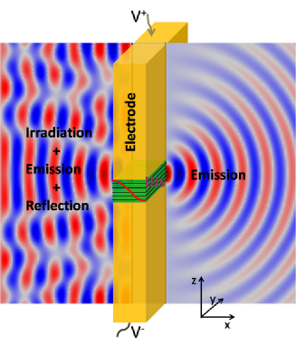
The setup is shown in Fig. 1, where a stack of IJJs are sandwiched by two ideal conductors with infinite thickness. These two conductors prevent the interference between EM waves from the two edges of IJJs stack. The left side of IJJs is exposed to irradiation. We assume that the IJJs are infinitely long in the direction, and thus the problem reduces to two dimensions with sizes and . This setup is similar to the one proposed in Ref.Bulaevskii et al. (2008), except for the lateral size m which contains cavity modes in the THz regime.
The dynamics of the gauge invariant phase difference in IJJs is described by the inductively coupled sine-Gordon equationsSakai et al. (1993); Bulaevskii et al. (1996); Lin and Hu (2008); Hu and Lin (2009)
| (1) |
where is the gauge invariant phase difference at the -th junction, the normalized -axis conductivity, the inductive coupling; is the dielectric constant and is the conductivity along the -axis, and is the lattice period in the -direction; is the light velocity in vacuum; and are the penetration depths along the -axis and -axis respectively. In Eq.(1), the lateral space is normalized by , time by the Josephson plasma frequency , and the external current by the Josephson critical current Lin et al. (2008). is the second-order difference operator defined as . We adopt and , which are typical for BSCCO Lin and Hu (2009). The physics discussed below is valid in a stack of IJJs with huge , which has not yet been achieved in artificial Josephson junction stacksUstinov et al. (1993); Sakai et al. (1993).
In the absence of irradiation, the so-called dynamic boundary condition (DBC) was derived based on Maxwell equations Bulaevskii and Koshelev (2006); Koshelev and Bulaevskii (2008). It is easy to generalize the DBC to incorporate irradiation because Maxwell equations are linear. Assuming the incident wave is a plane wave with the electric field polarized along the axis and the propagation direction normal to the left edge of IJJs, the total electric field on the left side is
| (2) |
where with the outgoing wave comprising the emitted and reflected waves, the incident wave with a relative phase difference to the Josephson plasma oscillation inside IJJs, the frequency, and the normalized dielectric constant of the dielectric medium coupled to the IJJs Lin et al. (2008). For simplicity of analysis, we concentrate in Eq.(2) on the case that the frequency of Josephson plasma determined by the bias voltage according to the ac Josephson relation is equal to the incident frequency, since otherwise the response of IJJs is very small.
The EM wave at the right edge comes only from emission. The generalized boundary conditions for the oscillating electromagnetic fields in the real space and frequency domain are given byBulaevskii et al. (2008)
| (3) |
| (4) |
where and are the total electric and magnetic fields, and with is the impedance Bulaevskii and Koshelev (2006). The power of the incident wave is . Since the thickness of the IJJs stack used in experiments is m, much smaller than the wave length in the THz band, the electromagnetic fields are uniform in the direction in the IJJs for THz waves as in Eqs. (3) and (4). There exists a significant impedance mismatch between the IJJs and the dielectric medium, which is crucial for the cavity resonances. With the relations and ,Lin and Hu (2009) one obtains the boundary condition for the oscillating part of .
A solution to Eq.(1) is given intuitively by
| (5) |
where the first term at the right-hand side (r.h.s) is the uniform rotating phase according to the ac Josephson relation and the second term is the plasma oscillation. The spatial modulation of plasma oscillation is induced by both radiation and irradiation. We consider the region of small plasma oscillation . From terms with time dependence , we obtain the equation for by substituting Eq.(5) into Eq. (1)
| (6) |
Equation (6) has the solution
| (7) |
with and for weak damping as in the case of BSCCO system. The first term in Eq. (7) represents the uniform plasma oscillation, and the other two terms are propagating waves due to radiation and irradiation, with the two coefficients and determined by the boundary condition Eqs. (3) and (4).
The IV characteristics is derived from the current conservation relation
| (8) |
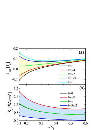
where denotes the average over space and time. Besides the normal current due to the quasiparticles , the total dc current has two contributions from the plasma oscillation due to the nonlinearity of the dc Josephson effect: and associated with the uniform and nonuniform parts of plasma oscillation in Eq.(7). The IV curves for different ’s are displayed in Fig. 2(a) for the incident wave . When one fixes the voltage satisfying the phase-locking relation and sweeps the current, the relative phase adjusts itself to match the current, which traces out the Shapiro steps Shapiro (1963). Zero-crossing Shapiro steps Kautz (1996) occur at small voltages. For , is given explicitly as
| (9) |
is maximized (minimized) at (), and the height of the Shapiro step is given by . In the region where , a dc power is converted into emission. When , the incident EM wave is converted into dc power and charges the IJJs, and the IJJs effectively work as a battery.
The radiation powers measured by the Poynting vector satisfy the power balance condition with the dissipation caused by the quasiparticles, and and the radiation at the left and right edge respectively. The emission at the right edge is depicted in Fig. 2(b) for . It is clear that the emission is always very weak because of lack of an efficient way to pump energy into plasma oscillation in this state. In the same limit, the radiation power is given by
| (10) |
It is clear that the emission comprises of spontaneous one , the one caused by transmitted wave and the stimulated one .
The state given in Eq.(5) is found to become unstable when the incident frequency and the bias voltage get close to , where the cavity mode with is induced by the irradiation (without losing generality, here we consider the first cavity mode). Instead of Eq.(5) the phase dynamics should then be described by Lin and Hu (2008)
| (11) |
where is the static phase kink associated with the cavity mode. Substituting Eq. (11) into Eq. (1), we obtain the following equations
| (12) |
and
| (13) |
Since the Josephson plasma should take the form
| (14) |
where , we arrive at with . Due to that the dominant term in Eq.(14) is antisymmetric with respect to , Eq. (13) has a solution of kinks alternatingly piled up in the -axisLin and Hu (2008). Because of the huge inductive coupling in BSCCO, the phase kinks render themselves as step functions, and are stable against the radiation and irradiation provided . The width of a kink should be smaller than the junction width , which gives an estimate on the regime where the kink state is stable.
Although it has been revealed theoretically that the kink state is ideal for generating strong terahertz electromagnetic waves Lin and Hu (2008); Hu and Lin (2009), the dynamic process to realize the state was not clear. The present study indicates that irradiating the junction stack by an incident wave can stimulate the kink state.
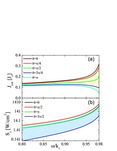
The dc supercurrent induced by the plasma oscillation in the kink state can be evaluated by . It includes the current associated with the plasma oscillations at the cavity mode , and that with radiation and irradiation . The IV characteristics with the irradiation of is given in Fig. 3(a). For and , we have
| (15) |
Because of the phase kinks, now is maximized (minimized) at () in contrast to Eq. (9). The height of the Shapiro step is . As is well known, Shapiro steps are suppressed by internal modes in single junctions. It is the same case for a IJJs stack if the state is uniform along the -axis, since Eqs.(1) are decoupled. Therefore, the appearance of a Shapiro step at the cavity resonance can be used as an exclusive detection of the kink state in a stack of IJJs.
The radiation power at the right edge is depicted in Fig. 3(b) for . It is clear that the input wave is enhanced significantly near the cavity frequency, where the kinks stimulated by the irradiation pump a large amount of dc power from the dc bias into Josephson plasma oscillation.
The radiation power at the right edge in the same limit is given by
| (16) |
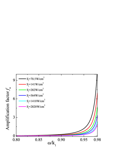
An amplification factor can be defined by the maximal value of the ratio with respect to the phase for a given . For the kink state, one has
| (17) |
which is achieved at . As displayed in Fig. 4, the amplification factor reaches its maximum at . An incident wave of power of can be amplified by one order of magnitude. The amplification factor decreases with the power of incident wave, and the maximum power which can be amplified by this technique is estimated as .
In a single junction, the presence of irradiation may cause chaotic dynamics in a certain parameter spaceKautz (1996), which is harmful for applications. The chaos can be avoided when the frequency of the incident wave is much larger than the Josephson plasma frequencyKautz (1996); Wang et al. (2001), which is fulfilled in a IJJs stack of length smaller than .
In conclusion, simultaneously shining a terahertz electromagnetic wave and biasing a dc voltage on a stack of intrinsic Josephson junctions stimulates the standing wave of Josephson plasma, which develops phase kinks in the junctions, when the frequency equals to one of the cavity frequencies of the junction stack. At the cavity resonance, the rotating kinks pump a large amount of dc energy into Josephson plasma oscillation, and the incident wave gets amplified. The maximal radiation power reached by this terahertz amplifier is estimated as . Since the strong plasma oscillation induces a large dc supercurrent at the cavity resonance, the system can work as a terahertz detector. The response of the system to irradiation depends on the spatial structure of the superconductivity phase, thus the phase dynamics may be probed by the irradiation.
This work was supported by WPI Initiative on Materials Nanoarchitronics, MEXT, Japan and CREST-JST Japan. Calculations were performed on the Numerical Materials Simulator (SGI Altix supercomputer) in NIMS.
References
- Barone and Paterno (1982) A. Barone and G. Paterno, Physics and Applications of The Josephson Effect (Wiley, 1982).
- Kleiner et al. (1992) R. Kleiner, F. Steinmeyer, G. Kunkel, and P. Müller, Phys. Rev. Lett. 68, 2394 (1992).
- Ferguson and Zhang (2002) B. Ferguson and X. C. Zhang, Nat. Mater. 1, 26 (2002).
- Tonouchi (2007) M. Tonouchi, Nat. Photon. 1, 97 (2007).
- Hu and Lin (2009) X. Hu and S. Z. Lin, Supercond. Sci. Technol. 23, 053001 (2010) (review article).
- Ozyuzer et al. (2007) L. Ozyuzer, A. E. Koshelev, C. Kurter, N. Gopalsami, Q. Li, M. Tachiki, K. Kadowaki, T. Yamamoto, H. Minami, H. Yamaguchi, T. Tachiki, K. E. Gray, W. -K. Kwok, U. Welp, Science 318, 1291 (2007).
- Bulaevskii and Koshelev (2006) L. N. Bulaevskii and A. E. Koshelev, Phys. Rev. Lett. 97, 267001 (2006).
- Lin and Hu (2008) S. Z. Lin and X. Hu, Phys. Rev. Lett. 100, 247006 (2008).
- Koshelev (2008) A. E. Koshelev, Phys. Rev. B 78, 174509 (2008).
- Shapiro (1963) S. Shapiro, Phys. Rev. Lett. 11, 80 (1963).
- Doh et al. (2000) Y. J. Doh, J. H. Kim, K. T. Kim, and H. J. Lee, Phys. Rev. B 61, R3834 (2000).
- Wang et al. (2001) H. B. Wang, P. H. Wu, and T. Yamashita, Phys. Rev. Lett. 87, 107002 (2001).
- Latyshev et al. (2001) Y. I. Latyshev, M. B. Gaifullin, T. Yamashita, M. Machida, and Y. Matsuda, Phys. Rev. Lett. 87, 247007 (2001).
- Bae et al. (2008) M. H. Bae, R. C. Dinsmore, M. Sahu, H. J. Lee, and A. Bezryadin, Phys. Rev. B 77, 144501 (2008).
- Bulaevskii et al. (2008) L. N. Bulaevskii, A. E. Koshelev, and M. Tachiki, Phys. Rev. B 78, 224519 (2008).
- Sakai et al. (1993) S. Sakai, P. Bodin, and N. F. Pedersen, J. Appl. Phys. 73, 2411 (1993).
- Bulaevskii et al. (1996) L. N. Bulaevskii, D. Domínguez, M. P. Maley, A. R. Bishop, and B. I. Ivlev, Phys. Rev. B 53, 14601 (1996).
- Lin et al. (2008) S. Z. Lin, X. Hu, and M. Tachiki, Phys. Rev. B77, 014507 (2008).
- Lin and Hu (2009) S. Z. Lin and X. Hu, Phys. Rev. B 79, 104507 (2009).
- Ustinov et al. (1993) A. V. Ustinov, H. Kohlstedt, M. Cirillo, N. F. Pedersen, G. Hallmanns, and C. Heiden, Phys. Rev. B 48, 10614 (1993).
- Koshelev and Bulaevskii (2008) A. E. Koshelev and L. N. Bulaevskii, Phys. Rev. B 77, 014530 (2008).
- Kautz (1996) R. L. Kautz, Rep. Prog. Phys. 59, 935 (1996).