Surface Plasmon Polariton Mach-Zehnder Interferometer and Oscillation Fringes
Abstract
We present a quantitative experimental analysis of a surface plasmon polariton (SPP) interferometer relying on elliptical Bragg mirrors. By using a leakage radiation microscope we observe oscillation fringes with unit visibility at the two interferometer exits. We study the properties of the SPP beam splitter and determine experimentally both the norm and phase of the SPP reflection and transmission coefficients.
Progress in the field of two-dimensional optics at the micro- and nanometer scale requires necessarily the control over coherence of wave propagation in a confined environment. In this context it has been experimentally shown a few years ago that surface plasmon polaritons (SPPs, electromagnetic waves confined at the interface of a metal and a dielectric Raether ) can generate a variety of two-dimensional interference effects Hecht ; Sergy ; Harry2 .
More recently we were able to implement two-dimensional SPP Mach-Zehnder interferometers fabricated on silver thin films by lithographic techniques Harry1 ; Aurelien1 . The observation of SPP propagation relied on the interaction of a layer of fluorescent molecules deposited on top of the SPP sustaining silver surface. The fluorescence intensity was detected with conventional far-field microscopy providing a map of the lateral SPP field intensity profile Harry2 . As a major drawback, fluorescence imaging could not be exploited quantitatively as the dye molecules photo-bleach rapidly, and do so in dependence of the local SPP intensity.
For this reason we shifted our attention towards leakage radiation microscopy (LRM) which relies on the coupling of SPP waves to leaky light modes propagating in the dielectric substrate supporting the metal thin film Hecht ; Bouhelier . The leakage radiation is collected by an immersion objective optically coupled to the substrate which allows to acquire an image of the SPP profile in the metal surface Andrey . The advantage of LRM is that quantitative analysis can be performed since the intensity recorded at any point of the microscope image plane is proportional to the SPP intensity at the conjugate point in the object plane. We used LRM previously to analyze the interaction of SPPs with a line of gold protrusions on a silver film acting as a SPP beam splitter Andrey , as well as the propagation of SPPs in a corral constituted by confocal elliptical Bragg mirrors on a gold film Aurelien1 .
Here, we present a quantitative analysis of a Mach-Zehnder interferometer for SPP waves and we show in particular that we can record interference oscillation with unit visibility at the two interferometer exits.
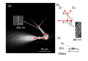
The experimental basics of the SPP interferometer considered here rely on results obtained in Refs. Harry1 and Aurelien1 . SPPs are launched locally on a gold thin film by focussing a laser beam (Titane:Sapphire, nm) incident normally to the substrate through a microscope objective (50, numerical aperture ) on a gold ridge ( nm width, nm height) on the film. The ridge and all other structures on the gold film as discussed in the following were fabricated by electron beam lithography (EBL). First, the structure geometries are defined by electron beam exposure, various chemical development steps and the deposition of nm thick SiO2. Then, second, the whole substrate is covered by a nm thick gold film. The SPPs propagate in the directions normal to the ridge axis and are reflected upon interaction with elliptical Bragg mirrors. The Bragg mirrors are made of individual protrusions of nm diameter and nm center-to-center distance. These protrusions are arranged in order to constitute five confocal ellipses. The distance between the two ellipse foci and equals the minimal long axis length . Since we work with a Bragg mirror the variation of the long axis length between two consecutive ellipses must be where is an integer and is the SPP wavelength fixed here at nm. We choose and nm. With these parameters we achieve mirror reflectivity up to . As in Ref. Harry1 we consider a Mach-Zehnder configuration. The two SPP beams launched at the ridge and reflected by the elliptical Bragg mirror are focused onto a beam splitter made of a line of individual protrusions ( nm diameter, center-to-center distance nm). In order to exploit the optical properties of elliptical mirrors the SPPs are launched at the first focal point . Accordingly, the beam splitter is positioned at the second focal point , where the two reflected SPP beams intersect (see Fig. 1 and Fig. 4). As we will see later we can adjust the phase in the interferometer by changing the lateral position of the ridge within different interferometers. Therefore, we consider several similar interferometers built by EBL on the same sample.
We start our investigation by considering a half-interferometer, i.e., a configuration where only one half of the elliptical Bragg mirror is present (see Fig. 1). SPP waves propagating into the left arm are thus not reflected and cannot interfere with the SPP waves propagating in the right arm. As a consequence the SPP wave initially launched to the right splits at into two output SPP waves and with normalized intensity (transmissivity), and (reflectivity) such that assuming no scattering. Fig. 1a shows a LRM image corresponding to this half-interferometer configuration and revealing a perfect symmetry between and . Fig. 2a shows a transverse cross-cut of the intensity in the two output SPP beams which confirms this symmetry quantitatively.
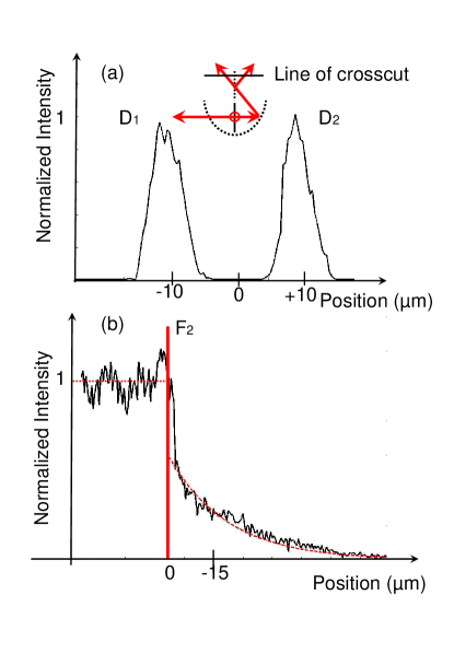
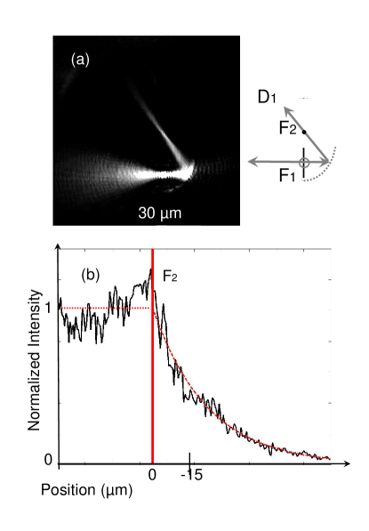
Fig. 2b shows a cross-cut along the SPP beam reflected by the right Bragg mirror, i.e., through and . Comparison with the corresponding cross-cut for a sample where no beam splitter is present (see Fig. 3) shows that the SPP intensity is reduced by a factor of two by the presence of the beam splitter. This justifies the assumption that no scattering takes place. The presented results are all consistent with the parameters of a 50/50 lossless beam splitter, i. e. . The SPP intensity decay in the branch located after can be well reproduced by an exponential function where is the distance separating the observation point from , and m is the SPP propagation length. The latter value agrees well with literature values for a nm thick gold film Raether .
It is important to note that with such an half-interferometer we do not have experimental access to the phase relation between the transmitted, reflected, and incident beams. In order to define this relation we must first recall some properties of a lossless . From the unitarity of the transfer matrix Zeilinger and from energy conservation one can deduce that the relation between the reflection and transmission amplitudes and is such that where . However, the sign depends on internal properties of the beam splitter and cannot be deduced from simple unitarity considerations. An individual study of each physical case is thus necessary. The simplest experimental way to do that is to consider the interferometer configuration including both (left and right) parts of the elliptical Bragg mirror, i. e. the complete interferometer. However, in order to explain the predictions of this interferometry experiment one has to take carefully into consideration all the phase shifts and differences introduced during SPP propagation.
In this context it has been remarked Theseharry that one can mimic the behavior of SPP waves launched from on the ridge by using the scalar field produced by a linear and continuous distribution of 2D dipoles. These in-plane dipoles are orthogonal to the ridge and proportional in strength to the incident electric field Remark2 . From this hypothesis and from symmetry considerations we deduce that there is a phase difference of between the SPPs propagating into the right and into the left arm of the interferometer. The pertinence of this fact has been experimentally observed for the elliptical SPP corral Aurelien1 . Indeed, this phase difference justifies why we can observe SPP intensity oscillations at the second focal point when rotating the in-plane laser beam polarization at . This result is not in conflict with the previous analysis of the symmetric and lossless beam splitter. Indeed, the phase difference of characterizes an ideal lossless beam splitter coupling an incident mode to two output modes.
However, the beam splitter is supposed to be lossless, as confirmed by our first analysis of the half-interferometer case, and we thus deduce that the intensities in the two exits and of the interferometer are given by
| (1) |
is the SPP coupling efficiency at the ridge. is the algebraic displacement of the ridge with respect to the symmetry axis of the interferometer (defining the symmetric configuration) and is the real part of the SPP wave vector. defines a variable phase difference responsible for the oscillation of the intensities at and . We note that we neglected the small contribution of the imaginary part of the SPP wave vector since for Remark . Depending on the sign of the phase shift at the beam splitter we obtain two possible solutions
| (2) |
which invert the role of and , respectively.
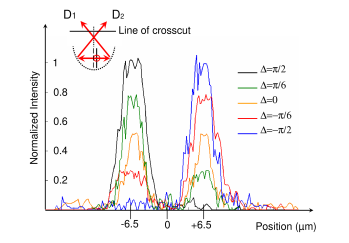
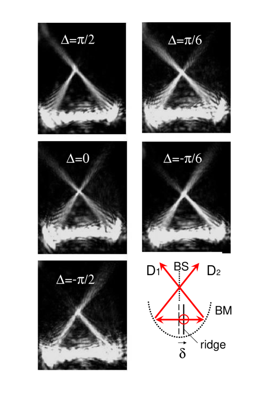
Experimentally we changed discontinuously between different individual interferometers fabricated on one sample to obtain a variation of the phase in the domain . Fig. 4 shows the according sequence of LRM images corresponding to phase differences , and . Since the SPP wavelength is fixed to nm the displacement is thus varying in the interval . In this sequence of images we clearly observe the intensity oscillation in the SPP beams and as a function of . In order to be quantitative we consider transversal cross-cuts of the two exit beams, corresponding to the cross-cut in Fig. 2. All these cross-cuts were taken from the same position for all interferometers,i. e. for all values of (see inset on Fig. 5). From this analysis one can deduce the interferograms plotted in Fig. 6.
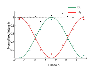
Clearly the two plots corresponding to the exits and are in opposition of phase as requested for a Mach-Zehnder interferometer. Energy conservation is fulfilled since after normalization (see Fig. 6). The data show a perfect consistency with the model given by Eq. 1 in the case of a phase shift . The fringe visibility Born is close to unity and agrees with the values deduced from the expression (submitted to the energy conservation condition ). We can thus with a good approximation write and .
To conclude, we presented a detailed experimental analysis of SPP interferometry. Therefore, we analyzed LRM images of a Mach-Zehnder interferometer relying on elliptical Bragg mirrors, and we analyzed quantitatively the reflection and transmission of SPP waves by the lossless beam splitter . This leads to the experimental relations and between the SPP transmission and reflection coefficients of . We observed fringes oscillations with unit visibility at the two exits of the interferometer as well as the opposition of phase between the two signals and when changing the length of the two interferometer arms by an amount , i. e. when changing the phase by the quantity . The conservation of energy is fulfilled since we have whatever the phase difference . All experimental observations are in good quantitative agreement with the analytical calculations. This forms a solid base for further investigations or applications of SPP interferometry.
For financial support the Austrian Science Foundation and the European Union, under projects FP6 NMP4-CT-2003-505699 and FP6 2002-IST-1-507879 are acknowledged.
References
- (1) H. Raether, Surface Plasmons(Springer, Berlin, 1988).
- (2) B. Hecht, H. Bielefeldt, L. Novotny, Y. Inouye, and D. W. Pohl, Phys. Rev. Lett. 77, 1889 (1996).
- (3) S. I. Bozhevolnyi, and F. A. Pudonin, Phys. Rev. Lett. 78, 2823 (1997).
- (4) H. Ditlbacher, J. R. Krenn, N. Felidj, B. Lamprecht, G. Schider, M. Salemo, A. Leitner, and F. R. Aussenegg, Appl. Phys. Lett. 80, 404 (2002).
- (5) H. Ditlbacher, J. R. Krenn, G. Schider, A. Leitner, and F. R. Aussenegg, Appl. Phys. Lett. 81, 1762 (2002).
- (6) A. Drezet, A. L. Stepanov, H. Ditlbacher, A. Hohenau, B. Steinberger, F. R. Aussenegg, A. Leitner, and J. R. Krenn, Appl. Phys. Lett. 86, 074104 (2005).
- (7) A. Bouhelier, Th. Huser, H. Tamaru, H. -J. Güntherodt, D. W. Pohl, Fadi I. Baida and D. Van Labeke, Phys. Rev. B. 63, 155404 (2001).
- (8) A. stepanov, J. R. Krenn, H. Ditlbacher, A. Hohenau, A. Drezet, B. Steinberger, A. Leitner, and F. Aussenegg, Opt. Lett. 30,1524 (2005)
-
(9)
A. Zeilinger, Am. J. Phys. 49, 882 (1981).
C. H. Holbrow, E. Galvez, and M. E. Parks, Am. J. Phys. 70, 260 (2002). - (10) H. Ditlbacher, Phd Thesis, Karl-Franzens Universität Graz (2003).
-
(11)
Each dipole generate at a scalar field
Hecht ; Harry2 ; Drezet . is the distance separating the source located at from the observation point, and is the angle between the dipole and the vector position going from the source to the observation point. The dipole is induced by the local electric field and thus where is the dipole polarizability. - (12) M. Brun, A. Drezet, H. Mariette, N. Chevalier, J. C. Woehl, and S. Huant, Europhys. Lett. 64, 634 (2003).
- (13) If we don’t neglect the SPP damping we obtain and for respectivelly the signal and . Here we have .
- (14) M. Born and E. Wolf, Principles of Optics (Cambridge University Press, Cambridge, 1999).