How to erase surface plasmon fringes
Abstract
We report the realization of a dual surface plasmon polariton (SPP) microscope based on leakage radiation (LR) analysis. The microscope can either image SPP propagation in the direct space or tin the Fourier space. This particularity allows in turn manipulation of the LR image for a clear separation of different interfering SPP contributions present close to optical nanoelements .
The miniaturization of optical elements and devises into nanoscale dimensions is restricted by the diffraction limit to about half of the effective light wavelength. One promising way to avoid this restriction is the use of surface plasmon polaritons (SPPs) instead of light waves. SPPs are quasi-two-dimensional electromagnetic waves of electron excitations, propagating at a metal-dielectric interface and having field components decaying exponentially into both neighboring media Raether . As was recently demonstrated Hecht ; Bouhelier ; Stepanov , to image the spatial SPP profile, besides near-field optical microscopy Weeber or fluorescence mapping Harry , leakage radiation (LR) imaging microscopy can be applied. It was shown that this new approach allows for quantitative measurements of the spatial SPP field profile by deducing SPP reflection, transmission, and scattering efficiencies for various surface nanostructures Stepanov ; Drezet . In parallel to this LR microscopy in the direct space it has been recently experimentally demonstrated that LR imaging is equivalently possible in the Fourier space Barnes ,e. g., imaging in the SPP wavevector space. Here, based on the use of a dual LR microscopy working in both the direct and Fourier space, we present the next development of LR imaging microscope and we discuss new possibilities for imaging and controlling of SPPs. In particular we show how by acting in the Fourier space this method can be applied to erase from the final image in the direct space SPP interferences fringes existing close to structure like Bragg mirror Harry ; Drezet . This in turn allows quantitative analysis in a spatial region where near field optics can not resolve and distinguish the different SPP field components contributing to the SPP image.
The intensity decay length of a plane SPP wave in a perfectly planar metal film between two dielectric media defines its intrinsic decay length , which is a measure of the ”ideality” of the electron gas. is defined as the imaginary part of the complex SPP wave vector . Intrinsic losses are caused by inelastic scattering of conduction electrons, scattering of electrons at interfaces and leakage radiation LR Raether . LR is emitted from the interface between a metal thin film and the higher refractive index medium (glass substrate) Stepanov ; Drezet . When the electromagnetic SPPs field cross the metal film and reach the substrate, LR appears at a characteristic angle of inclination with respect to the interface normal. At this angle the LR wave satisfies sin, where is the wave vectors of LR, being the refractive index of the glass substrate, and the SPP wavelength. Although LR contributes to SPP damping, it permits the direct mapping of the SPP propagation at the air/metal interface. Indeed, the intensity collected at any point of the image plane of the LR microscope with a charged-coupled-device (CCD) camera is directly proportional to the intensity of SPPs at the conjugate point located on the air/metal boundary, i. e. , in the object plane of the microscope. Stepanov ; Drezet .
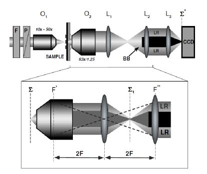
The new LR microscope with the improvements discussed in the following is sketched on Fig. 1. Like in the previous version of the LR microscope Stepanov ; Drezet and in order to avoid total internal reflection inside the glass substrate, an oil immersion objective 63, numerical aperture of 1.25) in contact with the bottom part of the sample is used to collect LR images. It is important to remark that simultaneously to LR the incident exiting laser beam is going through the sample and the microscope contributing subsequently to the total signal in the plane. This direct laser light dominates the SPP signal in the region of excitation in . This feature is conserved in where some distortions due to saturation of the camera are even added to the resulting image. It is consequently impossible to separate SPPs propagation from the incident beam in the vicinity of the excitation region. However, as well known from Fourier optics one can distinguish these two contributions by observing the intensity distribution in the back focal plane of the immersion objective. Indeed since the signal collected in is a cartography of the 2D momentum distribution of photons emitted in the SPP distribution is thus confined on a circle corresponding to . Additionally, the central beam (with an angular divergence much smaller than ) is located at the center of this circle. By introducing a central beam-block in it is then possible to eliminate the direct contribution of the laser beam. By contrast with the previous version of LR microscope Stepanov we included this beam block in the optical setup. Since however is contained in the immersion objective we must first image , in a plane , by using a lens in a 2f-2f configuration. In we can introduce the central beam-block (see Fig. 1). In order to image the SPP propagation in the direct space we introduce two auxiliary lenses and focusing light on the CCD ( is located in ). By changing the focal length of one can either image the Fourier plane or the object plane (image of through and ). This dual microscope is consequently able of recording SPPs propagation either in the direct or in the Fourier space.
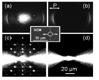
In order to illustrate the potentiality of this optical setup we consider different nanostructures obtained by usual electron beam lithography (EBL) Krenn on a 60 nm thick gold film. For the local excitation of SPPs we focus a linearly polarized light from a Ti:sapphire laser (wavelength: nm) through a microscope objective onto a gold ridge (200 nm wide, 60 nm high). Launched SPPs propagate to the left and to right of the ridge in the direction perpendicular to the ridge axis. Figs. 2a, b, c, d show LR images of SPPs corresponding to this configuration (:50, numerical aperture 0.7). Figs. 2a and c correspond to imaging in the Fourier and direct space respectively. The central spot associated with the laser beam and the partial ring associated with the SPPs cone are clearly visible on Fig. 2a. This laser beam saturates the image in the direct space and creates some artefact in the launching region as visible on Fig. 2c. Figs. 2b,d show the same images with the central beam block introduced in the plane . As a consequence of this introduction the multiple artefact disappear from the image in the direct space resulting in improvements of image quality and eliminating the spurious effect of the incident laser light (see Fig. 2d).
As a further modification, we introduced the use of different
objectives for focusing of the laser beam. The different focus
diameters achievable with the various objectives of focal lenght
allow in turn the generation of SPP waves of different
divergence angles. Indeed the convergence angle of the
laser beam on the sample is connected to the laser beam diameter
mm just before the lens by the relation
. Due to Heisenberg’s relation we have
in the sample plane where
is the focus beam diameter in the sample plane. Since SPPs
launched from the ridge obey to the same Heisenberg relation we
conclude that the divergence angle of the SPP beam equals
, i. e. the convergence angle of the laser beam. This
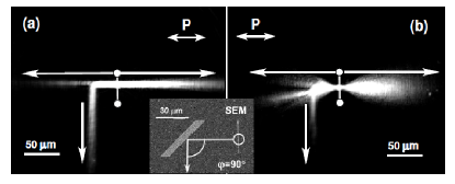
principle is illustrated in Fig. 3 which shows LR images of SPPs
launched by a ridge and reflected by a Bragg mirror Harry ; Drezet ; Weeber . The Bragg mirror considered here has been
optimized for incidence angle with respect to the
direction normal to Bragg’s mirror in the sample plane. The mirror
is made of gold ridges (60 nm height, 140 nm wide) separated by a
distance as described in
Weeber . Comparison of Fig. 3a (: 10, NA=0.25)
with Fig. 3b (: 50, NA=0.7) show clearly that the
Bragg mirror is much more efficient with a parallel beam
(, see Fig. 3a) that with a divergent beam
(, see Fig. 3b). This method of generating a
parallel SPPs beam can be considered as an alternative to prism
technics used in PSTM imaging Weeber . The black shadow in
the transmitted beam of Fig. 3b shows directly in counterpart the
reflectivity acceptance angle of the Bragg mirror. Both approach
can be thus useful for understanding SPPs reflectivity of such
system. Additionally it must be added that in order to observe
SPPs reflectivity with a narrow beam like in Fig. 3a the use of
the central beam block is necessary. Indeed without this beam
block the laser beam of diameter m would
saturate the recorded signal in the region of interest between the
ridge and the Bragg mirror. The effect is less pronounced for
divergent beam where
m.
It should be however remarked that the potentiality of such a dual
LR microscope are not limited to correction of artefact or
improvement in LR images quality. Indeed the definition of Fourier
optics itself allow us to manipulate the images in order to
extract some relevant physical information hidden in the pictures.
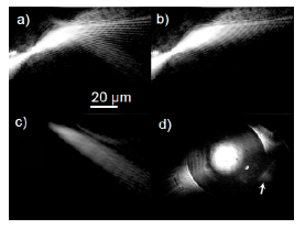
This is illustrated in Fig. 4 which shows LR images of SPP
reflected at large incidence angle (e. g. ,
) on a Bragg mirror like the one
shown in Fig. 3. Interference between the incident and reflected
SPP field give rises to fringes in the region close to the mirror
(see Fig. 4a). The presence of interference prohibit a simple and
direct analysis of SPP reflection. However as shown in Fig. 4d the
LR image in the Fourier space separates clearly the respective
contributions of the incoming laser beam (the central spot), of
the incident SPP launched from the ridge (the two arcs of circle),
and of the reflected SPP beam (indicated by an arrow). By
positioning adequately a beam block in this Fourier plane one can
remove not only the incoming laser beam but selectively image
either the incident and transmitted beams (see Fig. 4b) or the
reflected beam (see Fig. 4c) alone. The interference fringes are
clearly erased from the LR pictures. This method in turn allow
direct quantitative analysis not directly possible with the
previous existing methods Harry ; Stepanov ; Weeber .
In summary, Thus, based on conventional microscopy dual LR imaging
proves to be a quick and reliable technique for probing SPP fields
with the advantage of providing possible quantitative analysis in
both Fourier and direct space. This dual method is particulary
adapted to analysis of SPP propagation in region where different
beams interfere and where different contributions can thus be
selectively erased for subsequent analysis.
The authors thank M.U. González for test-sample preparation.
For financial support, the European Union under projects FP6
NMP4-CT-2003-505699, FP6 2002-IST-1-507879 and the Lisa Meitner
programm of the Austrian Scientific Foundation (M868-N08) are
acknowledged.
References
- (1) H. Raether, Surface Plasmons(Springer, Berlin, 1988).
- (2) B. Hecht, H. Bielefeldt, L. Novotny, Y. Inouye, and D. W. Pohl, Phys. Rev. Lett. 77, 1889 (1996).
- (3) A. Bouhelier, Th. Huser, H. Tamaru, H.-J. Güntherodt, D. W. Pohl, F.I. Baida, D. Van Labeke Phys. Rev. B 63, 155404 (2001).
- (4) A. Stepanov, J. R. Krenn, H. Ditlbacher, A. Hohenau, A. Drezet, B. Steinberger, A. Leitner, and F. Aussenegg, Opt. Lett. 30,1524 (2005).
- (5) J.-C. Weeber, M. U. González, A.-L. Baudrion, and A. Dereux, Appl. Phys. Lett. 87, Appl. Phys. Lett. 87, 1 (2005).
- (6) H. Ditlbacher, J. R. Krenn, G. Schider, A. Leitner, and F. R. Aussenegg, Appl. Phys. Lett. 81, 1762 (2002).
- (7) A. Drezet, A. L. Stepanov, H. Ditlbacher, A. Hohenau, B. Steinberger, F. R. Aussenegg, A. Leitner, and J. R. Krenn, Appl. Phys. Lett. 86, 074104 (2005).
- (8) W. L. Barnes, Opt. Express 13, 428 (2005).
- (9) A. Hohenau, H. Ditlbacher, B. Lamprecht, J. R. Krenn, A. Leitner, F. R. Aussenegg, to appear in Microelec. Engin. (2006).