Sensitive gravity-gradiometry with atom interferometry: progress towards an improved determination of the gravitational constant.
Abstract
We here present a high sensitivity gravity-gradiometer based on atom interferometry. In our apparatus, two clouds of laser-cooled rubidium atoms are launched in fountain configuration and interrogated by a Raman interferometry sequence to probe the gradient of gravity field. We recently implemented a high-flux atomic source and a newly designed Raman lasers system in the instrument set-up. We discuss the applications towards a precise determination of the Newtonian gravitational constant . The long-term stability of the instrument and the signal-to-noise ratio demonstrated here open interesting perspectives for pushing the measurement precision below the 100 ppm level.
1 Introduction
Matter-wave interferometry has recently led to the development of new techniques for the measurement of inertial forces, finding important applications both in fundamental physics and applied research. The remarkable stability and accuracy that atom interferometers have reached for acceleration measurements can play a crucial role for science and technology. Quantum sensors based on atom interferometry had a rapid development during the last decade and different schemes were demonstrated and implemented. Atom interferometry is used for precise measurements of gravity acceleration [1, 2, 3], Earth’s gravity gradient [4, 5], and rotations [6, 7]. Currently, experiments based on atom interferometry are in progress to test Einstein’s Equivalence Principle [8, 9] and to measure the Newtonian gravitational constant G [10, 11, 12], while experiments on tests of general relativity [9], for search of quantum gravity effects [13, 14, 15] and for gravitational waves detection [16, 17] have been proposed. Accelerometers based on atom interferometry have been developed for many practical applications including metrology, geodesy, geophysics, engineering prospecting and inertial navigation [5, 18, 19, 20]. Ongoing studies show that the space environment will allow us to take full advantage of the potential sensitivity of atom interferometers [21, 22].
Our atom interferometer MAGIA (acronym of: Accurate Measurement of G by Atom Interferometry) was developed for a precise determination of the Newtonian gravitational constant . The basic idea of the experiment and some preliminary results are presented in [23, 10, 24, 12]. We recently improved the experimental set-up by implementing a high-flux atomic source based on a 2D-MOT and a newly designed Raman lasers system.
The Newtonian gravitational constant plays a key role in the fields of gravitation, cosmology, geophysics, and astrophysics and is still the least precisely known among the fundamental constants. Based on the weighted mean of eight values obtained in the past few years [25], in 2006 the Committee on Data for Science and Technology (CODATA) recommended a value with a relative uncertainty of 100 ppm. Although measurements have improved considerably since 1998[26], the available values are still in poor agreement. Indeed, while the most precise measurements of have assigned uncertainties lower than 50 ppm [27, 28, 29, 30, 31], the results differ by many standard deviations among each other. From this point of view, the realization of conceptually different experiments can help to identify still hidden systematic effects and therefore improve the confidence in the final result. With a few exceptions [30, 32, 33], most experiments were performed using conceptually similar schemes based on suspended macroscopic masses as probes and torsion balances or pendula as detectors. In our experiment, freely falling atoms act as probes of the gravitational field and an atom interferometry scheme is used to measure the effect of nearby well-characterized source masses. The projected accuracy for MAGIA shows that the results of the experiment will be significant to discriminate between existing inconsistent values.
2 Principle of measurement and experimental apparatus
The principle of the MAGIA experiment, the scheme of Raman interferometry and its application to measure as well as our experimental apparatus have been described in previous papers [23, 10, 34, 12] and references therein. Here we give a brief review, while in sections 2.1, 2.2 and 2.3 we describe the recent progress of the experiment.
In our experiment, 87Rb atoms, trapped and cooled in a magneto-optical trap (MOT), are launched upwards in a vertical vacuum tube with a moving optical molasses scheme, producing an atomic fountain. Near the apogee of the atomic trajectory, a measurement of their vertical acceleration is performed by a Raman interferometry scheme [1]. External source masses are positioned in two different configurations and the induced phase shift is measured as a function of masses positions. In order to suppress common-mode noise and to reduce systematic effects, a double-differential scheme has been adopted. The vertical acceleration is simultaneously measured in two vertically separated positions with two atomic samples, that are launched in rapid sequence with a juggling method. From the differential acceleration measurements as a function of the position of source masses, and from the knowledge of the mass distribution, the value of can be determined.
In a Raman interferometry-based gravimeter, atoms in an atomic fountain are illuminated by a sequence of light pulses which split, redirect, and recombine the atomic wave packets. The light pulses are realized with two laser beams, whose frequencies and are resonant with the -type transition of a three-level atom with two lower states and and an excited state . The laser beams, propagating along the vertical -axis in opposite directions, are used to drive two-photon Raman transitions between and .
Atoms are first prepared in the state . During the interferometer sequence, a -pulse with duration , being the two photon Rabi frequency, splits the atom wavefunction into an equal superposition of and . The interaction with the Raman beams not only modifies the internal state of the atom, but italso results in a momentum exchange by an amount of ( ) that modifies the atomic trajectories. Successively, a -pulse with a duration of switches back the internal state from to and vice versa, re-directing the atomic trajectories. Finally, a pulse recombines the atomic packets in the two complementary output ports of the interferometer. At the end of the interferometer, the probability of detecting the atoms in the state is given by , where represents the phase difference accumulated by the wave packets along the two interferometer arms. In the presence of a gravity field, atoms experience a phase shift depending on the local gravitational acceleration and on the time interval between the Raman pulses [1]. The gravity gradiometer consists of two absolute accelerometers operated in differential mode. Two spatially separated atomic clouds in free fall along the same vertical axis are simultaneously interrogated by the same Raman beams to provide a measurement of the differential acceleration induced by gravity on the two samples.
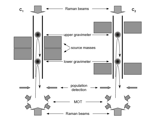
Fig. 1 shows a schematic of the MAGIA experiment. The gravity gradiometer setup and the configurations of the source masses ( and ) are visible. At the bottom of the apparatus, a magneto-optical trap (MOT) with beams oriented in a 1-1-1 configuration collects 87Rb atoms. Using the moving molasses technique, the sample is launched vertically along the symmetry axis of the vacuum tube and cooled down to a temperature of K. The gravity gradient is probed by two atomic clouds moving in free flight along the vertical axis of the apparatus and simultaneously reaching the apogees of their ballistic trajectories at 60 cm and 90 cm above the MOT. Such a geometry, requiring the preparation and the launch of two samples with a high number of atoms in a time interval of about 100 ms, is achieved by juggling the atoms loaded in the MOT [10]. Shortly after launch, the two atomic samples are velocity selected and prepared in the state using a combination of a Raman pulse and resonant blow-away laser pulses. Typically atoms are left after velocity selection. The interferometers take place at the center of the vertical tube shown in Fig. 1. In this region, surrounded by two -metal shields (76 dB attenuation factor of the magnetic field in the axial direction), a uniform magnetic field of 250 mG along the vertical direction defines the quantization axis. The field gradient along this axis is lower than G/mm. After the Raman interferometry sequence, the population of the ground state is measured in a chamber placed just above the MOT by selectively exciting the atoms on the hyperfine levels and sequentially detecting the resulting fluorescence.
Each atom interferometer in the gravity gradiometer measures the local acceleration with respect to the common reference frame identified by the wave fronts of the Raman lasers. Therefore, even if the phase noise induced by vibrations on the retroreflecting mirror completely washes out the atom interference fringes, the signals simultaneously detected on the upper and lower accelerometers remain coupled and preserve a fixed phase relation. As a consequence, when the trace of the upper accelerometer is plotted as a function of the lower one, experimental points distribute along an ellipse. The differential phase shift is then obtained from the eccentricity and the rotation angle of the ellipse best fitting the experimental data [35].
The source masses [24] are composed of 24 tungsten alloy (INERMET IT180) cylinders, for a total mass of about 516 kg. They are positioned on two titanium platforms and distributed in hexagonal symmetry around the vertical axis of the tube. Each cylinder is machined to a diameter of 100 mm and a height of 150 mm after a hot isostatic pressing treatment applied to compress the material and reduce density inhomogeneities. The two platforms can be precisely translated along the vertical direction by four step motors, with a resolution of 2 m provided by an optical encoder [24].
The MAGIA apparatus has been recently upgraded. The main changes concern the atomic source to load the MOT, the Raman laser system and the shape of source masses. In the preliminary measurement of described in [12], the statistical uncertainty amounted to while the systematic uncertainty amounted to . The major contributions to the systematic uncertainty budget came from the knowledge of the position of the source masses with respect to the atomic trajectories and of the atomic initial velocity.
In the present work, we have addressed both the systematic uncertainty and the long term stability to show that they are compatible with a measurement of at the level of 100 ppm. We discuss improvements on source mass positioning in section 2.3 while an estimate of the uncertainty on atomic velocity is discussed in section 3.2.
2.1 2D-MOT
In the experiment reported in [12], the magneto-optical trap was loaded from the background Rb vapour obtained from a dispenser. A major disadvantage of such approach was the obvious trade-off between MOT loading rate and background pressure in the vacuum system. Indeed, a high Rb vapour density is important for a fast MOT loading, but it also degrades the vacuum inducing higher atom losses along the all interferometer sequence and more background fluorescence at detection.
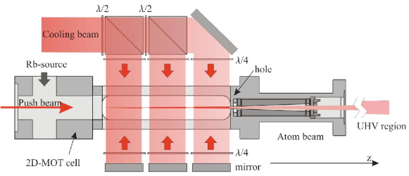
To achieve fast loading rates while preserving a very low background pressure in the MAGIA vacuum system, a high flux atomic source based on a two-dimensional magneto-optical trap (2D-MOT) [36] has been implemented. Atoms evaporate from a temperature controlled rubidium reservoir and, through a 15 mm diameter tube, they enter a vapor cell with dimensions of mm (see fig. 2). The cell is machined from a single piece of titanium and 4 rectangular windows ( mm) are glued to its sides for optical access. Two sets of coils are attached to the cell to provide the desired radial magnetic gradients of about 20 Gauss/cm. Two orthogonal beam pairs of cooling laser with repumper overlapped enter the vapor cell through the rectangular windows and radially cool the atoms. For sake of compactness of the optical setup each beam is split into three circularly polarized parts with 24.5 mm beam-diameter. A low intensity laser beam, slightly red detuned from the cooling transition and propagating along the axial direction, pushes the atoms increasing the flux in the direction of the 3D-MOT chamber. As a result, an atomic beam is coupled out through a hole (1.5 mm diameter) at the back wall of the cell (2 mm thick). Before entering the UHV chamber, whose center is at about 0.5 m distance from the 2D-MOT, the generated atomic beam passes through a tube of purified graphite with a conical hole for differential pumping.
The laser system used to operate the 2D-MOT is based on a home-made Master Oscillator - Power Amplifier (MOPA) with output power of about 500 mW. The master is an extended cavity diode laser using an interference filter for wavelength selection [37]. Two double-pass AOMs allow independent frequency and power tuning of the cooling and pushing beams. Optimal atomic flux from the 2D-MOT source is found when the optical frequencies of such beams are red tuned from the transition by 8 and 13 MHz, respectively.
Under typical operating conditions, measured values for the atomic beam flux, mean axial velocity, velocity spread and atomic beam divergence are atoms/s, 15 m/s, 7 m/s, and 23 mrad, respectively.
As compared to the standard operating conditions of the dispenser previously employed to load the 3D-MOT, when using the 2D-MOT the background Rb density is reduced by more than two orders of magnitude in the UHV chamber. Fig. 3 shows typical values of the MOT loading rate versus the temperature of the Rb oven in the 2D-MOT system. As compared to the standard operating conditions of the dispenser previously employed to load the 3D-MOT, the MOT loading rate can be increased by up to a factor 5. Since the signal to noise ratio in the interferometer scales as the square root number of atoms, this change is expected to improve the sensitivity of our gravity gradiometer by about a factor 2.2.

2.2 Raman laser system
The Raman beams are generated by two home-made MOPA systems with output power of about 700 mW each (see fig. 4). Two interference filter stabilized extended cavity diode lasers are phase-locked with an offset frequency of about 6.8 GHz generated by a microwave synthesizer. In addition, one of the two lasers (master laser) is frequency locked with an offset of about 2 GHz to the transition, by detecting the beat note with a frequency stabilized laser (reference laser). Each laser beam injects an indipendent Tapered Amplifier (TA). Such system has several advantages as compared to the apparatus previously employed in the experiment. Indeed, interference stabilized extended cavity diode lasers have lower intrinsic frequency noise than Littrow grating stabilized lasers, sensibly improving the locking stability and the mean time between unlock events. In addition, using two independent tapered amplifiers instead of a single one allows independent control on the intensity of the two Raman beams. Fluctuations in the Raman beams intensity might cause drifts in the measured gravity gradient through the light shift effect. Such scheme also provides higher optical power for the Raman beams. The higher Rabi frequency has two effects: it results in a higher efficiency of Raman transitions; moreover, the Raman lasers interact with a larger class of atomic velocities. In our setup, the overall optical power of Raman beams after the optical fiber is about 200 mW.
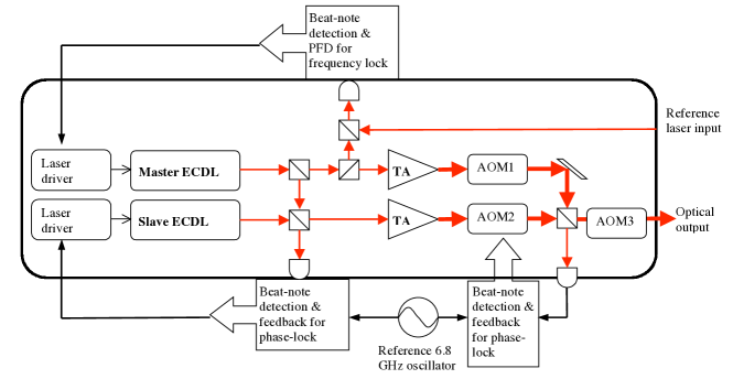
Our Raman laser system features a double-stage optical phase-locked loop (OPLL). The primary OPLL detects the beat note between the two ECDL beams before injection of the TA, in such a way to minimize the signal propagation delay and to maximize the loop bandwidth. We mix the beat note with the 6.8 GHz reference frequency and we compare the downconverted signal with a reference frequency from a Direct Digital Synthesizer (DDS) in a fast digital phase-frequency detector (Motorola MC100EP140). The DDS frequency is swept around 40 MHz with a linear frequency ramp to compensate for the change in Doppler effect during the interferometric sequence. The resulting error signal is properly filtered and used to drive two actuators on one of the ECDL (slave Raman laser), namely, the PZT holding the output coupler and the injection current of the laser diode. The loop bandwidth on the injection current is about 4 MHz. The output beams from the TAs are passed through two AOMs for independent intensity control, and are finally recombined in a polarizing beam splitter. A third, single-pass AOM is used for pulse shaping just before coupling the Raman beams into an optical fiber.
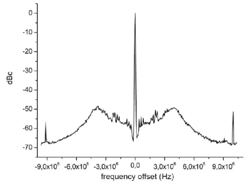
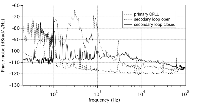
We also apply an auxiliary, low bandwidth loop in order to compensate for the phase noise introduced through the differential path of the two Raman laser beams before they are recombined in the optical fiber; to such purpose we detect the beat note between the Raman laser beams at the polarizing beam splitter before the third AOM; we mix the beat note with the 6.8 GHz reference frequency and we use another fast digital phase-frequency detector to compare the downconverted signal with the same MHz reference frequency employed in the primary loop. The resulting error signal is properly filtered and used to control a voltage controlled crystal oscillator (VCXO) driving the frequency of the AOM after the TA of the slave Raman beam. The resulting loop bandwidth is about 100 kHz. Fig. 5 shows the RF spectrum of the beat note between Raman laser, while fig. 6 shows the phase noise spectral density measured in different conditions: after the primary loop, after the optical fiber with the secondary loop open, after the optical fiber with the secondary loop closed.
2.3 Source masses
In the preliminary measurement of described in [12], one of the major contributions to the systematic uncertainty budget came from the knowledge of the position of the source masses with respect to the atomic trajectories; the corresponding contribution to the error on amounted to . While an estimate of the uncertainty on atomic trajectories is discussed in section 3.2, we recently improved the precision of mass positioning in two ways. First, we applied a polishing and rectification machining to the 24 cylinders. After such process, the shape of each cylinder is regular within m rms. Then, we tested the use of a laser tracker to measure the position of each cylinder. Since the shape of the cylinders is regular, the position is known once the center and tilt angle are measured. We place the target corner cube of the laser tracker on the upper face of the cylinder under analysis, and we measure its coordinates in several positions on the surface. We fit the measured data to a plane, thus obtaining the elevation and tilt angle of the cylinder. In the final configuration, the horizontal coordinates of the cylinder are measured by placing the corner cube on a small conical mark machined at the exact center of the plane surface. Our tests show that we can measure the relative position of our cylinders with a rms error below 5 m. As a result, the contribution of source mass positioning to the systematic relative uncertainty on can be reduced to the level of .
3 Experimental results
In order to characterize the apparatus, we tested the sensitivity of the gravity gradiometer and its stability on the time scale of a few days. We also investigated the atomic velocity to improve the systematic uncertainty in the measurement of .
3.1 Gradiometer sensitivity
As a first test of the sensitivity of our apparatus, we observed the statistical fluctuations of the gradiometer measurements over about 17 hours, keeping the masses in a fixed position. Fig. 7 shows a Lissajous figure obtained by plotting the normalized population of the ground state detected at the output port of the upper interferometer as a function of the same measurement performed at the output port of the lower interferometer [10]. Each point can be used to extract the two phases modulus of the two interferometers after a single experimental cycle. The repetition time of the experiment is about 2.5 s, and the plot contains about 25200 points.

The data have been divided in a series of 36 consecutive data points. Each group of 36 points was fitted with an ellipse and the value of the angle has been extracted with its estimated error. The optimal number of points required to fit an ellipse has been estimated by varying the number of points in the ellipse, evaluating the whole fit, and computing the Allan deviation for the series. As a figure of merit we consider , where is the Allan deviation at 1 ellipse, i.e. is the equivalent Allan deviation for a single point. Since the fit is heavily nonlinear drops sharply at first, then it reaches a plateau and finally starts to increase due to long term drifts. By choosing as the smallest value that reaches the plateau both and temporal resolution are optimized. With , we have 700 complete ellipses from the data shown in fig. 7.
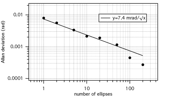
We have evaluated the Allan variance of the differential phase shift and verified that it scales as the inverse of the square root of the integration time, showing the typical behavior expected for white noise (see fig. 8). The instrument has a sensitivity of 70 mrad at 1 s, corresponding to a sensitivity to differential accelerations of at 1 s. The resulting sensitivity is about a factor two better than in [12], thus reducing by a factor 4 the integration time needed to reach a specific precision target in the measurement. The regime of 100 ppm uncertainty can now be reached in about 40 days of continuous measurement.
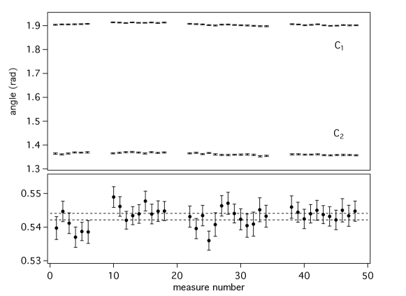
We also modulated the position of the source masses as shown in fig. 1. Fig. 9 shows a measurement of the differential interferometric phase on a period of 60 hours over four consecutive days. We moved the masses from the close () to the far () configuration and viceversa every 40 minutes, corresponding to 960 measurement cycles. We split each set of 960 points () in 40 series of 24 consecutive points; we fitted each group of 40 ellipses and we evaluated the average and the standard error on the average of the differential phase. In the sequence the linear drift in time was removed by comparing with the weighted average of and . In this way we obtained 39 couples of data . From each couple a value for the angle of rotation can be obtained. The final result is rad and the is 33. This is equivalent to a statistical uncertainty of on the measurement of .
3.2 Measurement of atomic velocity
In the preliminary measurement of described in [12], the contribution to the error on coming from the knowledge of the atomic initial velocity amounted to . In order to improve the error budget accounting for systematic effects on the measurement, we have refined the measurement of the vertical velocity of the atomic sample after velocity selection.
The measurement technique is based on Raman velocimetry. We apply a Raman pulse 350 ms after the velocity selection pulse. We change the frequency ramp on the Raman beams (see section 2.2) to successively reach the resonant condition on the pulse corresponding to the two possible configurations of the wave vector (upwards and downwards oriented). So the frequency difference between the two resonant peaks gives the mean velocity of the atomic cloud after velocity selection. We change the final frequency of the ramp to sweep through the two resonances.

Experimental data showing the resonant peaks are presented in fig. 10. By fitting the data with Lorentzian shapes we measure a frequency difference between the two peaks of Such frequency difference is related to twice the Doppler shift: Thus the atomic vertical velocity is measured with a precision . As a result, the contribution of the error on vertical atomic velocity to the systematic uncertainty on can be reduced below .
The degree of control of atomic velocity and source mass position is compatible with a measurement of with a target accuracy of 100 ppm. In such conditions, the systematic uncertainty may be limited by the knowledge of the atomic positions relative to the source masses, which is much less critical than source masses positioning in the MAGIA experiment. Because of the high density of tungsten, the gravitational field produced by the source masses is able to compensate for the Earth’s gravity gradient. Therefore, operating the interferometers close to stationary points of the gravitational potential strongly reduces the uncertainty on due to the knowledge of the atomic positions [12]. A knowledge of the atomic positions with millimeter precision (both vertically and radially) will be required to reduce the systematic uncertainty on below .
4 Conclusions
We presented a sensitive gravity gradiometer based on Raman atom interferometry. Recent upgrades to the MAGIA apparatus have allowed to reach a sensitivity to differential gravity accelerations of /s.
We also discussed the system performance for a measurement of the Newtonian gravitational constant. Our apparatus can run continuously for several days, showing a reproducibility of the gravity gradient measurement compatible with the stated sensitivity on such time scale. Our measurement of differential gravity gradient over four days is equivalent to a statistical uncertainty of on the measurement of .
We have refined the error contribution deriving from the main sources of systematic uncertainty in the experiment. In particular, the effect of both the knowledge of source masses positions and vertical atomic velocities on the error budget can be reduced well below 100 ppm.
In the next future, a measurement of with atom interferometry at the level of 100 ppm seems possible. With the demonstrated sensitivity, an integration time of about 40 days will be required for reaching such uncertainty level. Further improvements in the setup, such as the use of more sophisticated detection schemes [38] or the implementation of high momentum beam splitters [39], may enable an even higher sensitivity.
References
References
- [1] M. Kasevich and S. Chu. Measurement of the Gravitational Acceleration of an Atom with a Light-Pulse Atom Interferometer. Appl. Phys. B, 54:321, 1992.
- [2] A. Peters, C. K. Yeow, and S. Chu. Measurement of gravitational acceleration by dropping atoms. Nature, 400:849, 1999.
- [3] H. Müller, S.-W. Chiow, S. Herrmann, S. Chu, and K.-Y. Chung. Atom-Interferometry Tests of the Isotropy of Post-Newtonian Gravity. Phys. Rev. Lett., 100(3):031101, Jan 2008.
- [4] M. J. Snadden, J. M. McGuirk, P. Bouyer, K. G. Haritos, and M. A. Kasevich. Measurement of Earth’s Gravity Gradient with an Atom Interferometer-Based Gravity Gradiometer. Phys. Rev. Lett., 81:971, 1998.
- [5] J. M. McGuirk, G. T. Foster, J. B. Fixler, M. J. Snadden, and M. A. Kasevich. Sensitive absolute-gravity gradiometry using atom interferometry. Phys. Rev. A, 65:033608, 2002.
- [6] T. L. Gustavson, P. Bouyer, and M. Kasevich. Precision Rotation Measurements with an Atom Interferometer Gyroscope. Phys. Rev. Lett., 78:2046, 1997.
- [7] T. L. Gustavson, A. Landragin, and M. Kasevich. Rotation sensing with a dual atom-interferometer Sagnac gyroscope. Class. Quantum Grav., 17:2385, 2000.
- [8] S. Fray, C. Alvarez Diez, T.W. Hänsch, and M. Weitz. Atomic Interferometer with Amplitude Gratings of Light and Its Applications to Atom Based Tests of the Equivalence Principles. Phys. Rev. Lett., 93:240404, 2004.
- [9] S. Dimopoulos, P. W. Graham, J. M. Hogan, and M. A. Kasevich. General relativistic effects in atom interferometry. Phys. Rev. D, 78(4):042003, 2008.
- [10] A. Bertoldi, G. Lamporesi, L. Cacciapuoti, M. De Angelis, M. Fattori, T. Petelski, A. Peters, M. Prevedelli, J. Stuhler, and G. M. Tino. Atom interferometry gravity-gradiometer for the determination of the Newtonian gravitational constant G. Eur. Phys. J. D, 40:271, 2006.
- [11] J. B. Fixler, G. T. Foster, J. M. McGuirk, and M. Kasevich. Atom Interferometer Measurement of the Newtonian Constant of Gravity. Science, 315:74, 2007.
- [12] G. Lamporesi, A. Bertoldi, L. Cacciapuoti, M. Prevedelli, and G. M. Tino. Determination of the Newtonian Gravitational Constant Using Atom Interferometry. Phys. Rev. Lett., 100:050801, 2008.
- [13] G. M. Tino. High precision gravity measurements by atom interferometry. In I. Ciufolini, D. Dominici, and L. Lusanna, editors, 2001: A Relativistic Spacetime Odyssey - Proceedings of JH Workshop, Firenze, 2001. World Scientific, 2003.
- [14] G. Ferrari, N. Poli, F. Sorrentino, and G. M. Tino. Long-Lived Bloch Oscillations with Bosonic Sr Atoms and Application to Gravity Measurement at the Micrometer Scale. Phys. Rev. Lett., 97:060402, 2006.
- [15] G. Amelino-Camelia, C. Laemmerzahl, F. Mercati, and G. M. Tino. Constraining the Energy-Momentum Dispersion Relation with Planck-Scale Sensitivity Using Cold Atoms. Phys. Rev. Lett., 103:171302, 2009.
- [16] G. M. Tino and F. Vetrano. Is it possible to detect gravitational waves with atom interferometers? Class. Quantum Grav., 24:2167–2177, 2007.
- [17] S. Dimopoulos, P.W. Graham, J.M. Hogan, M.A. Kasevich, and S. Rajendran. Gravitational wave detection with atom interferometry. Physics Letters B, 2009.
- [18] A. Peters, K. Y. Chung, and S. Chu. High-precision gravity measurements using atom interferometry. Metrologia, 38:25, 2001.
- [19] A. Bresson, Y. Bidel, P. Bouyer, B. Leone, E. Murphy, and P. Silvestrin. Quantum mechanics for space applications. Appl. Phys. B, 84:545–550, 2006.
- [20] M. de Angelis, A. Bertoldi, L. Cacciapuoti, A. Giorgini, G. Lamporesi, M. Prevedelli, G. Saccorotti, F. Sorrentino, and G. M. Tino. Precision gravimetry with atomic sensors. Meas. Sci. Technol., 20:022001, 2009.
- [21] G. M. Tino et al. Atom interferometers and optical atomic clocks: New quantum sensors for fundamental physics experiments in space. Nuclear Physics B (Proc. Suppl.), 166:159–165, 2007.
- [22] S.G. Turyshev, U.E. Israelsson, M. Shao, N. Yu, A. Kusenko, E.L. Wright, C.W.F. Everitt, M. Kasevich, J.A. Lipa, J.C. Mester, et al. Space-based research in fundamental physics and quantum technologies. Int. J. Mod. Phys. D16 (12a), 1879:1925, 2007.
- [23] M. Fattori, G. Lamporesi, T. Petelski, J. Stuhler, and G. M. Tino. Towards an Atom Interferometric Determination of the Newtonian Gravitational Constant. Phys. Lett. A, 318:184, 2003.
- [24] G. Lamporesi, A. Bertoldi, A. Cecchetti, B. Duhlach, M. Fattori, A. Malengo, S. Pettorruso, M. Prevedelli, and G. M. Tino. Source mass and positioning system for an accurate measurement of . Review of Scientific Instruments, 78(7):075109, 2007.
- [25] P. J. Mohr, B. N. Taylor, and D. B. Newell. CODATA Recommended Values of the Fundamental Physical Constants: 2006. Rev. Mod. Phys., 80:633, 2008.
- [26] P. J. Mohr and B. N. Taylor. CODATA values of the fundamental constants 2000. Rev. Mod. Phys., 72:351, 2000.
- [27] J. H. Gundlach and S. M. Merkovitz. Measurement of Newton’s Constant Using a Torsion Balance with Angular Acceleration Feedback. Phys. Rev. Lett., 85:2869, 2000.
- [28] T. J. Quinn, C. C. Speake, S. J. Richman, R. S. Davis, and A. Picard. A New Determination of G Using Two Methods. Phys. Rev. Lett., 87:111101, 2001.
- [29] T. R. Armstrong and M. P. Fitzgerald. New Measurements of G Using the Measurement Standards Laboratory Torsion Balance. Phys. Rev. Lett., 91:201101, 2003.
- [30] S. Schlamminger et al. Measurement of Newton’s gravitational constant. Phys. Rev. D, 74:082001, 2006.
- [31] J. Luo, L.-C. Tu Q. Liu, C.-G. Shao, L.-X. Liu, S.-Q. Yang, Q. Li, and Y.-T. Zhang. Determination of the Newtonian Gravitational Constant with Time-of-Swing Method. Phys. Rev. Lett., 102:240801, 2009.
- [32] J. P. Schwarz, D. S. Robertson, T. M. Niebauer, and J. E. Faller. A Free-Fall Determination of the Newtonian Constant of Gravity. Science, 282:2230, 1998.
- [33] U. Kleinevoss, H. Meyer, A. Schuhmacher, and S. Hartmann. Absolute measurement of the Newtonian force and a determination of G. Meas. Sci. Technol., 10:487, 1999.
- [34] L. Cacciapuoti, M. de Angelis, M. Fattori, G. Lamporesi, T. Petelski, M. Prevedelli, J. Stuhler, and G. M. Tino. Analog+digital phase and frequency detector for phase locking of diode lasers. Rev. Sci. Instrum., 76:053111, 2005.
- [35] G. T. Foster, J. B. Fixler, J. M. McGuirk, and M. A. Kasevich. Novel Method of Phase Extraction Between Coupled Atom Interferometers Using Ellipse-Specific Fitting. Opt. Lett., 27:951, 2002.
- [36] K. Dieckmann, R. J. C. Spreeuw, M. Weidemüller, and J. T. M. Walraven. Two-dimensional magneto-optical trap as a source of slow atoms. Phys. Rev. A, 58:3891, 1998.
- [37] X. Baillard, A. Gauguet, S. Bize, P. Lemonde, P. Laurent, A. Clairon, and P. Rosenbusch. Interference-filter-stabilized external-cavity diode lasers. Optics Communications, 266(2):609–613, 2006.
- [38] G. W. Biedermann, X. Wu, L. Deslauriers, K. Takase, and M. A. Kasevich. Low-noise simultaneous fluorescence detection of two atomic states. Opt. Lett., 34:347, 2009.
- [39] H. Müller, S.-W. Chiow, S. Herrmann, and S. Chu. Atom Interferometers with Scalable Enclosed Area. Phys. Rev. Lett., 102(24):240403, Jun 2009.