A Frequency-Controlled Magnetic Vortex Memory
Abstract
Using the ultra low damping NiMnSb half-Heusler alloy patterned into vortex-state magnetic nano-dots, we demonstrate a new concept of non-volatile memory controlled by the frequency. A perpendicular bias magnetic field is used to split the frequency of the vortex core gyrotropic rotation into two distinct frequencies, depending on the sign of the vortex core polarity inside the dot. A magnetic resonance force microscope and microwave pulses applied at one of these two resonant frequencies allow for local and deterministic addressing of binary information (core polarity).
One of the most important goals of the modern information technology is the development of fast high-density non-volatile random access memories (RAM) that are energy efficient and can be produced using modern planar micro- and nano-fabrication methods. Magnetic nano-objects offer a convenient way to store binary information through their bi-stable properties, but the development of practical magnetic RAM requires to find a performant mechanism to reverse the magnetization inside individual cells Schumacher et al. (2003). One of the ways is to take advantage of the high dynamical susceptibility of magnetic nano-objects at their ferromagnetic resonance frequency. This resonance approach is particularly efficient for low dissipation materials, as it allows to concentrate the energy in a narrow frequency band and to reduce the energy cost of the reversal process by the quality factor of the resonance.
In a vortex-state magnetic nano-dot Guslienko (2008), the static magnetization is curling in the dot plane, except in the dot center where it is forming an out-of-plane vortex core Shinjo et al. (2000) of typical size of the exchange length 5-10 nm. The core can be directed either perpendicularly up or down relative to the dot plane, this bi-stability being characterized by the core polarity . Recent experiments demonstrated that the vortex core polarity can be reversed in zero applied magnetic field through the excitation of the gyrotropic rotation of the vortex core about its equilibrium position at the dot center Waeyenberge et al. (2006); Yamada et al. (2007). At , the frequency of this gyrotropic core rotation mode, , is identical for both core polarities, but the sense of this rotation depends on . Thus, for a given core polarity, the circular polarization of the microwave field – right or left depending on the sign of – discriminates the occurrence of the resonant microwave absorption by the vortex-state magnetic dot Curcic et al. (2008). When the radius of the core orbit increases, a distortion of the core profile characterized by the appearance of a tail having the magnetization direction opposite to that of the original core polarity occurs Yamada et al. (2007); Guslienko et al. (2008); Vansteenkiste et al. (2009). The magnitude of this tail depends solely on the linear velocity of the vortex core Guslienko et al. (2008). When the latter reaches the critical value at (where , , is the permeability of the vacuum, the saturation magnetization of the magnetic material, its gyromagnetic ratio, and its exchange constant), the core polarity suddenly – within few tens of picoseconds Lee et al. (2008); Hertel and Schneider (2006) – reverses.
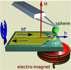
Still, reliable control of an individual cell in a large array based on resonant switching, which takes full advantage of the frequency selectivity of magnetic resonance, has to be realized. In this letter, we show that a frequency-controlled memory with resonance reading and writing schemes can be realized using vortex-state NiMnSb nano-dots placed in a perpendicular magnetic bias field . In our experimental realization, local adressing of the core polarity is achieved by means of a magnetic resonance force microscope (Fig.1). We also propose a more practical variant based on a full solid-state design.
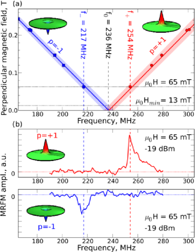
The key role of the static magnetic field aligned along the axis of the vortex core – being the sum of an homogeneous bias and of a small additional local component – is to introduce a controlled splitting of the frequency of the gyrotropic mode depending on the core polarity de Loubens et al. (2009). Therefore, the polarity state of individual magnetic dots can be selectively addressed by controlling the frequency of a linearly polarized microwave pulse excitation. When the core polarity is equal to (i.e. the core is parallel to H), the rotational frequency is larger than the frequency corresponding to the core polarity (i.e. the core is antiparallel to H). This frequency splitting is directly proportional to Ivanov and Wysin (2002); de Loubens et al. (2009) (see Fig.2a):
| (1) |
where is the magnetic field required to saturate the dot along its normal and is the frequency of the gyrotropic mode at , which can be approximated by the analytical expression Guslienko (2008): , where , is the thickness and the radius of the dot.
To design a practical memory cell it is necessary to choose the static magnetic field in such a way that the field-induced gyrotropic frequency splitting Eq.(1) exceeds the linewidth of the gyrotropic mode which can be approximately expressed as , where is the damping parameter for the gyrotropic core rotation mode Thiele (1973); Guslienko (2006), is the dimensionless Gilbert damping constant of the dot magnetic material and is the vortex core radius. Thus, the minimum perpendicular bias field is given by the expression:
| (2) |
(see Fig.2a). It follows from Eq.(2), that to reduce , it is necessary to choose the dot magnetic material with low damping and to increase the aspect ratio of the dot, as this leads to the decrease in the saturation field . To get a sufficient frequency separation between the modes with opposite core polarities it is convenient to have the magnitude of that is several times larger than .
The design of our experimental frequency-controlled magnetic vortex memory is presented in Fig.1. The memory elements are circular magnetic dots made of an epitaxial, ultra low damping half-Heusler alloy with high Curie temperature, NiMnSb(001) (, mT, K) Bach et al. (2003); Heinrich et al. (2004). Their aspect ratio ( nm, nm) is relatively large, and they are separated from each other by 10 m. The detailed magnetic characterization of such NiMnSb dots was performed in Ref. de Loubens et al. (2009) and yields the saturation field mT. An electromagnet is used to produce a tunable perpendicular magnetic field homogeneous on all the dots, and oriented perpendicular to the plane. This static field creates the above mentioned splitting of the gyrotropic frequencies for different core polarities. The dots are placed at the extremity of an impedance-matched gold microwave strip-line which provides an in-plane linearly polarized microwave magnetic field h. Since h contains both right and left circularly polarized components, it couples to the gyrotropic rotation of the vortex core for both core polarizations . This microwave field with variable frequency is used to resonantly excite gyrotropic rotation of the vortex core in a magnetic dot.
If the microwave field is weak, the amplitude of this gyrotropic rotation is relatively small, but sufficient to read the polarity of the rotating core (without destroying it) using the technique of magnetic resonance force microscope (MRFM), which is illustrated schematically in Fig.1 and described in detail in Ref. Klein et al. (2008). If the microwave field is sufficiently large and has the frequency corresponding to the resonance gyrotropic frequency for a given core polarity (e.g. for ), the velocity of the vortex core rotation induced by this field reaches the critical value, and the core polarity is reversed (written).
Achieving a dense memory requires to address the vortex core polarity state of a selected magnetic nano-dot inside an array. In our experimental memory prototype of Fig.1, we meet this challenge using the MRFM technique de Loubens et al. (2009); Klein et al. (2008). In the framework of this technique the magnetic probe glued to a soft cantilever is scanned horizontally over the different magnetic dots. This probe is a 800 nm diameter sphere made of amorphous Fe (with 3% Si), and its role is two-fold. First of all, it works as a sensitive local probe capable of detecting the change of the vertical () component of magnetization of a single magnetic dot caused by the gyrotropic rotation of the vortex core in this dot. Thus, it is possible to read the polarity of the vortex core in a selected dot de Loubens et al. (2009) (Fig.2b). Secondly, the dipolar stray field of the magnetic probe creates an additional local bias field of about 20 mT (i.e. roughly twice as large as mT), which allows one to single out the particular magnetic dot situated immediately under the probe in the information writing process. The presence of the local bias field created by the probe shifts the gyrotropic frequency in this dot by about , thus allowing one to choose the frequency of the microwave writing signal in such a way, that the reversal of core polarity is done in only the selected dot, without affecting the information stored in the neighboring dots.
In our experiments the total static magnetic field was chosen to be mT , which gave the following gyrotropic frequencies of the experimental magnetic dot: MHz, MHz, and MHz (Fig.2). The frequency linewidth of the gyrotropic rotation in the experimental dot was of the order of MHz.
The process of reading of the binary information stored in a magnetic dot is illustrated by Fig.2b. The amplitude of the cantilever oscillations is measured while the frequency of the weak (reading) microwave signal is varied in the interval containing and . The results of these measurements are shown for the cases when the vortex core polarity was set at or at the beginning of the microwave frequency sweep 111By saturating all the dots in a large positive – or, respectively, negative – static magnetic field.. It is clear from Fig.2b that the core polarity can be detected not only from the resonance signal frequency, which is different for different core polarities, but also from the sign of the MRFM signal de Loubens et al. (2009), which is positive for and negative for .
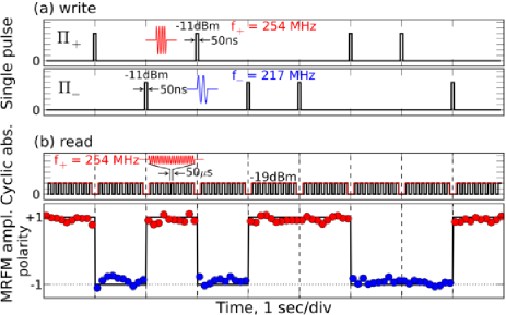
The writing process in a dot with initial core polarity equal to is illustrated by Fig.3. Fig.3a shows the frequency of the strong writing pulses of width ns and power W (corresponding to a microwave magnetic field of mT), while Fig.3b shows the frequency of the weak reading signal of power W, which is supplied continuously and is interrupted every second in order to apply a strong writing pulse. The frequency of the weak reading signal can be kept close to either or , and the amplitude of cantilever oscillations measured by MRFM provides the reading of the core polarity, as presented in Fig.3b for the case.
The application of the first writing pulse to a particular selected dot having the initial polarity results in the excitation of the vortex core rotation of the resonance frequency MHz and the amplitude which is sufficient to bring the vortex core to the threshold speed corresponding to the core polarity reversal Guslienko et al. (2008). Once inverted, the final state is out of resonance with the writing pulse (as ), so that the polarity can not be switched back to . It is clear from Fig.3 that the writing pulses of the carrier frequency (that we shall call -pulses) change the vortex core polarity from to , while the writing pulses of the carrier frequency (-pulses) change the core polarity from to . For the chosen parameters of the writing pulses the polarity reversal is deterministic: the reversal efficiency has been tested several hundred times without any failure, implying a success rate better than 99%. We also note that the application of the -pulse to the magnetic dot with the polarity (and application of a -pulse to the dot with ) does not have any effect on the vortex core polarity in the dot. Moving the MRFM probe to the neighboring dots during the reading sequence allows one to check that the core polarity in adjacent dots (situated 10 m away) is unaffected by the core reversal process in the selected dot. Thus, it has been demonstrated that the frequency-selective deterministic manipulation of the binary information has been achieved locally.
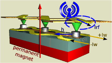
Although the experimental device shown in Fig.1 can be used as a prototype for the development of a frequency-controlled magnetic memory, a series of improvements can be imagined to make a more practical solid-state variant (Fig.4). Firstly, it would be useful to increase the dot aspect ratio to in order to reduce the dot saturation field , and, therefore, the minimum perpendicular bias magnetic field to mT (see Eq.(2)). In this case, a static bias field of only 20 mT, that could be produced by a permanent magnet placed underneath the substrate, should be sufficient to ensure reliable operation of the memory. Secondly, the dots of the practical variant should be arranged in a regular square array, where addressing of a particular dot is achieved by local combination of the static and microwave fields at the intersection of a word and a bit lines. The word line could be made in the form of a pair of wires running parallel to each row of dots at a 100 nm separation distance. A bias current mA would be sufficient to create an additional perpendicular field of 10 mT at the addressed row, causing an additional shift of the resonance frequency by about a full linewidth. The bit line could be made as an impedance matched wire running above each column of dots, producing the in-plane linearly polarized microwave field . Thirdly, it would be useful to replace the MRFM detection of Fig.1, which contains mechanically moving parts, by local electrical detectors of the absorbed power for the information reading process. Finally, we would like to point out that the proposed design offers the possibility to create a multi-register memory by stacking dots of different aspect ratios on top of each other, as they will have different resonance frequencies of the vortex core rotation.
This research was partially supported by the French Grant Voice ANR-09-NANO-006-01, by the European Grants DynaMax FP6-IST 033749 and Master NMP-FP7 212257, by the MURI Grant W911NF-04-1-0247 from the U.S. Army Research Office, by the Contract W56HZV-09-P-L564 from the U.S. Army TARDEC, RDECOM, and by the Grant No. ECCS-0653901 from the U.S. National Science Foundation.
References
- Schumacher et al. (2003) H. W. Schumacher, C. Chappert, R. C. Sousa, P. P. Freitas, and J. Miltat, Phys. Rev. Lett. 90, 017204 (2003).
- Guslienko (2008) K. Y. Guslienko, J. Nanosci. Nanotechnol. 8, 2745 (2008).
- Shinjo et al. (2000) T. Shinjo, T. Okuno, R. Hassdorf, K. Shigeto, and T. Ono, Science 289, 930 (2000).
- Waeyenberge et al. (2006) B. V. Waeyenberge, A. Puzic, H. Stoll, K. W. Chou, T. Tyliszczak, R. Hertel, M. Fähnle, H. Brückl, K. Rott, G. Reiss, et al., Nature (London) 444, 461 (2006).
- Yamada et al. (2007) K. Yamada, S. Kasai, Y. Nakatani, K. Kobayashi, H. Kohno, A. Thiaville, and T. Ono, Nature Mater. 6, 270 (2007).
- Curcic et al. (2008) M. Curcic, B. V. Waeyenberge, A. Vansteenkiste, M. Weigand, V. Sackmann, H. Stoll, M. Fähnle, T. Tyliszczak, G. Woltersdorf, C. H. Back, et al., Phys. Rev. Lett. 101, 197204 (2008).
- Guslienko et al. (2008) K. Y. Guslienko, K.-S. Lee, and S.-K. Kim, Phys. Rev. Lett. 100, 027203 (2008).
- Vansteenkiste et al. (2009) A. Vansteenkiste, K. W. Chou, M. Weigand, M. Curcic, V. Sackmann, H. Stoll, T. Tyliszczak, G. Woltersdorf, C. H. Back, G. Schütz, et al., Nature Physics 5, 332 (2009).
- Lee et al. (2008) K.-S. Lee, S.-K. Kim, Y.-S. Yu, Y.-S. Choi, K. Y. Guslienko, H. Jung, and P. Fischer, Phys. Rev. Lett. 101, 267206 (2008).
- Hertel and Schneider (2006) R. Hertel and C. M. Schneider, Phys. Rev. Lett. 97, 177202 (2006).
- de Loubens et al. (2009) G. de Loubens, A. Riegler, B. Pigeau, F. Lochner, F. Boust, K. Y. Guslienko, H. Hurdequint, L. W. Molenkamp, G. Schmidt, A. N. Slavin, et al., Phys. Rev. Lett. 102, 177602 (2009).
- Ivanov and Wysin (2002) B. A. Ivanov and G. M. Wysin, Phys. Rev. B 65, 134434 (2002).
- Thiele (1973) A. A. Thiele, Phys. Rev. Lett. 30, 230 (1973).
- Guslienko (2006) K. Y. Guslienko, Appl. Phys. Lett. 89, 022510 (2006).
- Heinrich et al. (2004) B. Heinrich, G. Woltersdorf, R. Urban, O. Mosendz, G. Schmidt, P. Bach, L. Molenkamp, and E. Rozenberg, J. Appl. Phys. 95, 7462 (2004).
- Bach et al. (2003) P. Bach, A. S. Bader, C. Rüster, C. Gould, C. R. Becker, G. Schmidt, L. W. Molenkamp, W. Weigand, C. Kumpf, E. Umbach, et al., Appl. Phys. Lett. 83, 521 (2003).
- Klein et al. (2008) O. Klein, G. de Loubens, V. V. Naletov, F. Boust, T. Guillet, H. Hurdequint, A. Leksikov, A. N. Slavin, V. S. Tiberkevich, and N. Vukadinovic, Phys. Rev. B 78, 144410 (2008).