Antiferromagnetic order in (Ga,Mn)N nanocrystals: A density functional theory study
Abstract
We investigate the electronic and magnetic properties of (Ga,Mn)N nanocrystals using the density functional theory. We study both wurtzite and zinc-blende structures doped with one or two substitutional Mn impurities. For a single Mn dopant placed close to surface, the behavior of the empty Mn-induced state, hereafter referred to as “Mn hole”, is different from bulk (Ga,Mn)N. The energy level corresponding to this off-center Mn hole lies within the quantum dot gap near the conduction edge. For two Mn dopants, the most stable magnetic configuration is antiferromagnetic, and this result was unexpected since (Ga,Mn)N bulk shows ferromagnetism in the ground state. The surprising antiferromagnetic alignment of two Mn spins is ascribed also to the holes linked to the Mn impurities that approach the surface. Unlike (Ga,Mn)N bulk, these Mn holes in confined (Ga,Mn)N nanostructures do not contribute to the ferromagnetic alignment of the two Mn spins.
I Introduction
Wide band-gap nitride semiconductors are currently used in full-color displays, white light sources, and ultraviolet laser diodes for high-density storage systems.Orton and Foxon (1998) Such semiconductors combine group-V nitrogen with elements of group III such as boron, aluminium, gallium, and indium. Recently, the well-known nitride compound GaN has been extensively investigated in the form of quantum dots, both with wurtziteWidmann et al. (1998); Bhaviripudi et al. (2007) and zinc-blendeMićić et al. (1999) crystal structures. The typical phenomena appearing in quantum dots are the discretization of the electronic spectra and the blue shift of the fundamental gaps.Wang and Herron (1990, 1991); Albe et al. (1998a, b); Pérez-Conde and Bhattacharjee (1999); Sapra and Sarma (2004); Echeverría-Arrondo et al. (2008) Moreover, the GaN nanocrystals can be doped with diluted magnetic impurities such as manganese. In fact, Ref. 12 shows (Ga,Mn)N quantum dots prepared under solvothermal conditions in the wurtzite phase. These particles seem to show a ferromagnetic signal in the ground state,Biswas et al. (2006) like bulk (Ga,Mn)N as calculated for diluted Mn spins.Das et al. (2003); d (2004); Hynninen et al. (2006) We must note that many experiments on bulk (Ga,Mn)N suggest that Mn spins are not diluted but forming clusters which give the observed ferromagnetism.Hynninen et al. (2006, 2006) A comparative ab-initio study between (Ga,Mn)N nanocrystals in wurtzite and zinc-blende phases is nevertheless missing.
In this work we investigate wurtzite and zinc-blende GaN quantum dots doped with one or two Mn impurities within density functional theory. The doping of nanocrystals with Mn atoms that replace host cations (MnGa) is actually possible, as already confirmed by several experiments on dots larger than ours.Norris et al. (2001); Besombes et al. (2004); Biswas et al. (2006); Hofmann et al. (2007) The experimental doping of small nanocrystals of about 1 nm in size has not yet been reported. However, it is expected from evidence of 2 nm undoped nanoparticles already synthesized. Hence, our calculations anticipate future experimental work with small doped dots. The theoretical and computational details are given in Sec. II. The case of (Ga,Mn)N nanoparticles doped with a single Mn impurity is studied in Sec. III. We show in this section that the doping reaction is endothermic and requires high temperatures as already confirmed by the experiments.Biswas et al. (2006) The case of (Ga,Mn)N crystallites doped with two Mn dopants is investigated in Sec. IV, where we show that the ground-state Mn impurities are antiferromagnetically aligned. The antiferromagnetic order of the two Mn spins is related to the different chemical environment around the empty state induced by the Mn dopant close to surface. Hereafter, we call “holes” these empty Mn-induced states which have mainly Mn character, but also N.d (2004); Raebiger et al. (2004, 2005); Marcet et al. (2006) This hole state lies within the nanocrystal gap near the conduction region and therefore does not contribute effectively to the ferromagnetic alignment of the two Mn impurities. The interesting role of the Mn holes near the surface is explained in Sec. III and Sec. IV. Then, (Ga,Mn)N quantum dots of about 2 nm in size would be likely antiferromagnetic. This possibility is interesting to be taken into account for spintronic applications based on such III-V Mn-doped nanostructures. Of course, the antiferromagnetic behavior of such small dots will also affect the overall magnetic character of granular solidsMoreno et al. (2002); Janik (2005); Gosk et al. (2006) formed by (Ga,Mn)N nanocrystals.
II Theory and Computations
We calculate (Ga,Mn)N quantum dots within density functional theory, following the Kohn-Sham scheme and the projector augmented-wave method, as implemented in VASP (Vienna Ab-initio Simulation Package).Kresse and Hafner (1993); Kresse and Furthmüller (1996); Kresse and Joubert (1999) Apart from the valence states inherent in semiconductors, we also take into account the Mn states. These latter electrons are responsible for the spin-splitted states at the gap edges through the - hybridization. For the exchange-correlation potentialPerdew et al. (1996) in the Kohn-Sham equations we use the generalized-gradient approximation (GGA+),Kresse and Joubert (1999); d (2003); Kresse and Joubert (1999, 1999, 1999); d (2003) in which and are special parameters that account for the strong Coulomb and exchange interactions between the Mn 3 electrons. We take and as calculated for Mn when doping bulk GaN.d (2004)
We investigate quasi-spherical nanocrystals of Å in diameter centered in a Ga position both with wurtzite and zinc-blende structures. We passivate the surface dangling bonds with pseudohydrogens (H∗)Huang et al. (2005) as an approach to quantum dots synthesized in colloidal solutions and also grown in semiconductor matrices. These fictitious atoms also prevent the appearance of surface states in the near-gap spectrum.Huang et al. (2005) Through passivation, every Ga (44) dangling bond at the dot surface is attached to a pseudohydrogen with a fractional charge of , and every N (22) dangling bond to a pseudohydrogen with a fractional charge of . Dot surfaces are perfectly saturated and free of defects so that we can avoid any perturbation and clearly investigate Mn-Mn magnetic interactions within nanocrystals. Anyhow, the influence of surface defects in the magnetic properties of Mn-doped dots is an interesting issue for further studies. The doped (Ga,Mn)N nanoparticles contain one or two Mn atoms which substitute for one or two Ga cations.
We use the supercell approximationHuang et al. (2005, 2005, 2005, 2005) to calculate wurzite and zinc-blende crystallites which are infinitely repeated in space. The size of the supercell is fixed to 22 Å so that surfaces of adjacent dots become separated by 10 Å and total energies are converged to meVs. This supercell size thus permits an accurate enough description of Mn-Mn magnetic interactions within nanocrystals. The atomic positions are fully relaxed until the forces on the atoms are small enough ( eV/Å). The input Ga-N bond lengths are taken from bulk GaN in the relaxed wurtzite and zinc-blende structures, Å. For wurtzite GaN, our calculated lattice constants are =3.24 Å and =5.29 Å; for zinc-blende GaN, our lattice constant is =4.59 Å. The cut-off energy in the plane-wave basis set is fixed to 500 eV in order to converge the total energies of bulk GaN and ferromagnetic MnN below 1 meV.
III Nanoparticles with a single Mn impurity
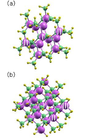
In this section we study GaN nanocrystals doped with a single Mn atom. The dopant concentrationsFatah et al. (1994) are for wurtzite quantum dots and for zinc-blende dots. These concentrations are in the same order of those used in the experiments.Biswas et al. (2006) The relaxed geometries are depicted in Fig. 1, where we see that the Mn impurity can occupy the central site labeled “I”, the off-center sites labeled “II”, and in zinc-blende particles also the sites labeled “III”. Positions II are near the crystal surface, not exactly at the surface. Since results concerning site III are dependent on the passivation species, in the following discussions we will focus on sites I and II.
III.1 Geometric expansion of N atoms around the Mn impurity
As we relax the atomic positions in (Ga,Mn)N quantum dots, we comment the influence of Mn doping on the crystal geometries. In the undoped nanoparticles the Ga-N bond lengths calculated for wurtzite and zinc-blende structures are Å for the central Ga cations and Å around the off-center Ga ions placed in site II. The smaller bond distances for position II as compared with position I are typically due to quantum dot surfaces. In the doped nanoparticles, the Mn-N bonds measure Å for the central-Mn case and Å around the off-center Mn dopants placed in site II. Therefore, as compared with the undoped structures, the N shell around Mn expands by , in close accordance with the 2 calculated expansion in wurtzite and zinc-blende bulk (Ga,Mn)N. We note that this expansion was not observed in II-VI (Cd,Mn)Te quantum dots,Echeverría-Arrondo et al. (2009) and is even contrary to the contraction around Mn dopants in III-V (In,Mn)P nanowires.Schmidt et al. (2006)
III.2 Quantum dot stability versus Mn position
We focus now on the energies involved in the formation and doping of (Ga,Mn)N nanocrystals. The cohesive energy of the undoped nanoparticle is defined in relation to the free atoms, , where is the energy of the th free atom, is the total ground-state energy, and is the number of atoms in the dot. Single-atom total energies are also obtained within the supercell approximation. The computed values are 3.607 eV/atom for the wurtzite structure and 3.593 eV/atom for the zinc-blende one. In undoped nanocrystals the wurtzite phase is thus more stable than the zinc-blende phase. However, since the growth of quantum dots (QDs) also depends on kinetics and other chemical potentials apart from those used in the cohesive energy, the undoped GaN crystallites can actually be synthesized both with wurtzite and zinc-blende structures.Widmann et al. (1998); Bhaviripudi et al. (2007); Mićić et al. (1999) Therefore, we are going to study Mn-doped GaN nanoparticles in both kind of geometries, wurtzite and zinc blende.
Anyhow, the energetics of Mn doping for both structures is studied by the following reaction,
| (1) |
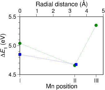
in which the Mn+2 dopant substitutes a Ga+3 cation in the quantum dot. Reaction (1) points to the main energy difference in the process of solvothermal growth during substitutional doping. The cationic form for the Mn dopant participates in reactions with the solvent which are beyond the scope of this work. For instance, these reactions may include precursors such as GaCl3 and MnCl2 in the presence of hexamethyldisilazane (HDMS).Biswas et al. (2006) Total energies of ions stem from the calculation of total energies of neutral atoms to which the first and second ionization energies (IEs) are summed up, that is, (Mn+2)(Mn)+1st IE + 2nd IE, where IE values are taken from the literature. The substitutional energy involved in reaction (1) is calculated against the Mn position and plotted in Fig. 2. Since this energy is positive, reaction (1) becomes endothermic and its activation requires high temperatures. This finding is in agreement with the experiments in which (Ga,Mn)N nanocrystals are prepared under solvothermal conditions at about 350 ∘C.Biswas et al. (2006) In addition, the substitutional energy is smaller for site II than for site I. This indicates that position II near the surface is more stable than position I, in accordance with previous calculations for substitutional Mn impurities embedded in II-VI QDsEcheverría-Arrondo et al. (2009) and also in III-V nanowires.Schmidt et al. (2006)
III.3 Local magnetic moments at the Mn and neighbor N sites
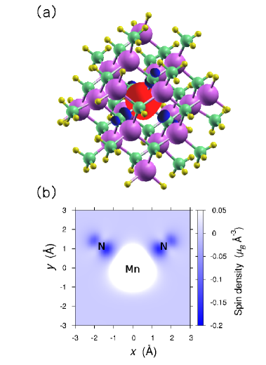
When doping (Ga,Mn)N nanocrystals with a single Mn impurity, one electron of the free Mn atom () transfers to its neighbor N anions and yields a configuration at the dopant position with a localized Mn hole.d (2003); Marcet et al. (2006) Nevertheless, the value of the local magnetic moment at the Mn site is different from 4 due to the - hybridization. This local moment is 3.99/4.10 when the Mn atom occupies the center of wurtzite/zinc-blende quantum dots and 3.88/3.88 when it is placed off-center in position II. Moreover, the Mn dopant induces the magnetic polarization of its neighbor N anions. In Fig. 3 we show for zinc-blende nanoparticles the spin density around the central Mn impurity and its four N neighbors. The integration of this density within spheres of Wigner-Seitz radii centered in the N atoms results in N local magnetic moments of -0.06/-0.09 for wurtzite/zinc-blende quantum dots. Small modifications of these radii would lead to roughly the same local moments with the same signs, as already seen for other Mn-doped nanocrystals.Echeverría-Arrondo et al. (2009) The exchange coupling between Mn and N magnetic moments is thus antiferromagnetic, as also calculated for bulk wurtzite and bulk zinc-blende (Ga,Mn)N.
We can compare the Mn local magnetic moments obtained for quantum dots and for bulk (Ga,Mn)N with similar Mn concentration. For bulk wurtzite , the computed Mn magnetic moment is 3.99; for bulk zinc-blende , the Mn magnetic moment is 4.03. These bulk values are hence similar to the previous Mn magnetic moments centered in wurtzite and zinc-blende (Ga,Mn)N nanocrystals. However, they show larger differences with respect to those moments calculated for Mn in site II near the surface. We shall see in next Sec. III.4 the local densities of states for further explanation about such larger differences.
III.4 Role of Mn hole in nanostructures
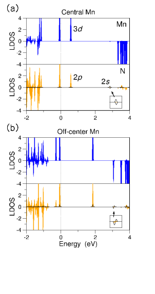
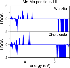
We investigate the hole linked to the Mn impurity by looking at the local densities of states for Mn in site I and site II close to surface. In Fig. 4 we show the local projections of the crystal states onto the Mn states and N states around the Mn dopant. The wurtzite case is given in Fig. 4(a) for a centered Mn impurity and in Fig. 4(b) for an off-center Mn placed in site II. From the densities of states we conclude that (i) the hole level associated with the central Mn dopant lies at around 0.6 eV near the Fermi energy; (ii) nevertheless, the hole level associated with the off-center Mn impurity lies at around 2 eV near the conduction region.
The zinc-blende densities of states are similar to the wurtzite densities apart from the central-Mn case which shows a triply degeneracy in the spin-up valence edge state. Such zinc-blende case is described in detail in Fig. 5. Due to the crystal field, the five 3 states of the central Mn atom are divided in two groups; one is composed of three -symmetry states and the other of two -symmetry states. The states of the Mn impurity hybridize with the -like states of its neighbor N atoms and yield the formation of bonding and antibonding states. The latter states are degenerate and only partially occupied due to the Mn hole. For zinc-blende nanoparticles with off-center Mn dopants and also for wurtzite dots, the crystal symmetry is -like.
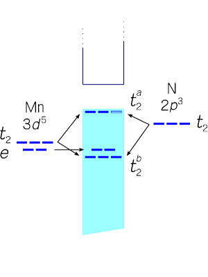
III.4.1 Gap-edge splittings and related - exchange constants
The - hybridization between the Mn 3 states and the host states yields an effective Mn-quantum dot exchange interaction that splits the crystal states at the gap edges.Larson et al. (1988) Note that we are interested in the change of III-V dot states by Mn impurities. The - energy splittings are explicitly given here and also rewritten in terms of - constants, and . Thereby, the rescaled splittings are interesting not only for theoreticians but also for experimentalists, both working on diluted magnetic compounds in the bulkd (1979); Larson et al. (1988) and in quantum dots.d (1983); Norberg and Gamelin (2006); m (2007)
The - exchange constants are defined with the following mean-field theory expressions:Bhattacharjee et al. (1983); Larson et al. (1988); Norberg and Gamelin (2006); Merad et al. (2006); Raebiger et al. (2004, 2005)
| (2) |
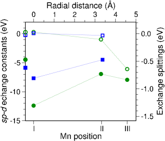
Here is the number of cations per unit volume;Bhattacharjee and Pérez-Conde (2003) is the splitting of the up and down Undoped Lowest Unoccupied Molecular Orbitals (ULUMOs); is the splitting of the up and down Highest Occupied Molecular Orbitals (HOMOs); and is the average Mn spin. The splittings and can be extracted from the local densities of states depicted in Fig. 4. The and exchange constants are calculated from Eq. (2) and presented in Fig. 6 together with for different Mn positions. Both wurtzite and zinc-blende values are larger for the central site I than for site II off-center, as it also happens for II-VI quantum dots doped with Mn.Echeverría-Arrondo et al. (2009)
The dependence of the exchange constant with the Mn position can be explained in more detail by looking at the valence states in the gap region. In Fig. 7 we show these states for two Mn sites, dot center and off-center position II. For the central-Mn case, the up-down HOMO splitting is large both for wurtzite and zinc-blende geometries. However, when Mn is moved off-center the spin-up valence levels decrease in energy and the spin-down levels slightly increase. These shifts are due to a smaller Mn-quantum dot exchange interaction caused by a smaller host charge density around position II. The up-down HOMO splittings for these Mn sites are consequently reduced as compared with those for the dot centers, and the exchange constants become hence smaller. We note that for the central-Mn case the charge of the up states is mainly distributed over the Mn impurity and its N neighbors, but for the down states it suffers a deplection around the Mn dopant that we ascribe to the fact that Mn and N are antiferromagnetically coupled. In addition, for Mn in position II the charge in the up HOMOs spreads perpendicularly to the axis and globally shows -like character.
The - exchange constants are different for nanoparticles than for bulk (Ga,Mn)N. In order to assess this difference, we calculate and for two bulk compounds with Mn concentrations which are similar to those in the studied crystallites. For bulk wurtzite we obtain eV and eV; for bulk zinc blende we obtain eV and eV. For comparison, these bulk constants are indicated in Fig. 6 as marks on the left axis. The values for Mn in positions I and II are comparable to the ones calculated for bulk wurtzite and bulk zinc blende. Moreover, the values are larger than the bulk ones for Mn in the central site I than in site II near the surface. Due to confinement, the hole level associated with the central Mn impurity is closer to the valence levels within the nanocrystal gap than in the bulk. The stronger exchange interaction between this Mn hole with -like character and the valence edge states increases the splitting of the up and down HOMOs and consequently the values. For position II as compared with position I, the off-center Mn hole lying near the conduction levels indicates a smaller interaction with the valence states, and hence smaller values.
IV Nanocrystals with two Mn impurities. Antiferromagnetic order in the ground state
In this section we investigate (Ga,Mn)N nanoparticles doped with two substitutional Mn impurities in the ferromagnetic and antiferromagnetic configurations. The ferromagnetic state is calculated for a total magnetic moment in the quantum dot (QD) of 8; the antiferromagnetic state is calculated for a null magnetic moment in the QD.
IV.1 Nanocrystal stability versus positions and magnetic alignments of the two Mn spins
By doping with two Mn ions we replace two Ga cations as described by the following reaction:
| (3) |
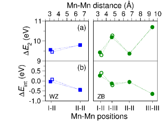
The required energy for this double substitution is referred to as and plotted in Fig. 8(a) for different Mn-Mn positions and magnetic alignments. As commented previously, the positive substitutional energies indicate that reaction (3) is endothermic and thus activated by increasing the temperature, as it occurs in the experiments.Biswas et al. (2006) Fig. 8 also shows that the most stable Mn impurities are aligned antiferromagnetically and placed in sites I-II close to surface. The calculated antiferromagnetic ground state was unexpected, since it is different from the ferromagnetic alignment of Mn spins in bulk (Ga,Mn)N.Das et al. (2003); d (2004); Hynninen et al. (2006) We relate it to the different role of the hole linked to the Mn dopant that approaches the surface. The energy of this hole lies within the nanocrystal gap near the conduction levels. Therefore, this Mn hole does not contribute effectively to the ferromagnetic order of the two Mn spins. As a consequence, the Mn-Mn coupling becomes antiferromagnetic in the ground state as it occurs for two Mn spins in II-VI (Cd,Mn)Te QDs.Echeverría-Arrondo et al. (2009)
We next study the interaction energy between the two Mn dopants which is defined as
| (4) |
Mn1 stands for the first Mn atom and Mn2 stands for the second Mn atom. The calculated interaction energies are plotted in Fig. 8(b) as a function of the positions and magnetic couplings of the two Mn spins. The interaction energy quantifies the relative stability of nanoparticles doped with one or two Mn impurities. Positive interaction values indicate that the two Mn dopants tend to occupy the same nanocrystal and negative values indicate that they tend to dope two different quantum dots individually. For instance, from Fig. 8(b) it can be seen that one crystallite with two antiferromagnetic Mn spins in positions I-II is more stable than two nanoparticles with two single Mn spins placed in sites I and II. We stress again that in doping reactions kinetics and other chemical potentials different from those used in the cohesive energy could also play an important role and may modify previous results concerning the stability of the nanostructures.
Since we are dealing with two Mn impurities, we calculate their local magnetic moments and total energies in the ferromagnetic and antiferromagnetic states. They are not explicitely given here but rewritten in terms of an effective Mn-Mn exchange interaction, quantified by , which is interesting not only for theoreticiansLarson et al. (1988); d (1987); Echeverría-Arrondo et al. (2009) but also for experimentalistsd (1987, 1987, 1987, 1987) working on diluted magnetic semiconductors. The exchange constant stems from the Heisenberg-like HamiltonianLarson et al. (1988) and it is thus defined as
| (5) |
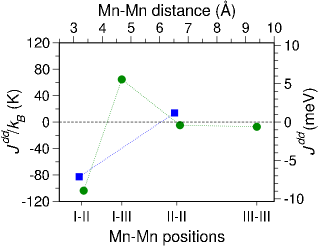
where is the total energy of the ferromagnetic state, is the total energy of the antiferromagnetic state, and is the local magnetic moment at the Mn1 site in Bohr magnetons. The exchange constants are calculated and plotted in Fig. 9 as a function of the Mn-Mn positions. Negative values mean antiferromagnetic alignments between Mn spins and positive values, ferromagnetic alignments. Fig. 9 shows also that in the most stable positions I-II the two Mn atoms are antiferromagnetically ordered unlike Mn spins in bulk ferromagnetic (Ga,Mn)N.
IV.2 The - exchange constants and Mn holes
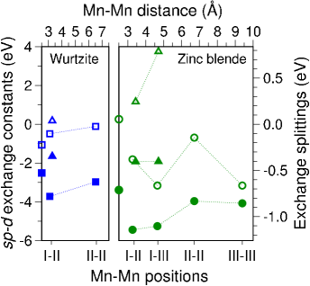
To look at the modification of the III-V dot states by Mn impurities, we now investigate the and exchange constants obtained from the calculated spin splittings at the gap edges and Eq. (2). The computed values are shown in Fig. 10 as a function of the positions and magnetic couplings of the two Mn spins. The main results are the following:
(i) and values are larger for ferromagnetic Mn spins in positions I-II than for farther apart Mn spins in positions II-II. This decrease is similar to that observed for two Mn spins in II-VI (Cd,Mn)Te quantum dots.Echeverría-Arrondo et al. (2009)
(ii) values are negative for ferromagnetic Mn spins. The hole levels associated with the off-center Mn impurities lie at high energies within the nanocrystals gaps and push the spin-up ULUMOs above the spin-down ULUMOs.
(iii) Positive values are larger for antiferromagnetic Mn spins placed in sites I-II than for a doped nanoparticle with a central Mn atom. The hole level linked to the spin-down Mn dopant located in site II pushes upward in energy the spin-down ULUMO and thereby increases the spin splitting of the ULUMOs corresponding to the single-Mn case.
(iv) Comparing Fig. 6 and Fig. 10 we see that the largest values are for wurtzite and zinc-blende quantum dots doped with a central Mn impurity.
As in the previous discussion of Sec. III.4, we now compare the and exchange constants for nanocrystals and for bulk (Ga,Mn)N. We calculate the bulk ferromagnetic compounds wurtzite and zinc-blende . The Mn concentration in bulk is similar to in wurtzite quantum dots; that of bulk is similar to in zinc-blende dots. For bulk wurtzite we obtain eV and eV; for bulk zinc blende we obtain eV and eV. These exchange values are shown for comparison in Fig. 10 as marks on the left axis. For wurtzite nanoparticles in the ferromagnetic configuration of Mn spins, the values are smaller than in the bulk; on the contrary, for zinc-blende quantum dots in the ferromagnetic state, the values are significantly larger than in the bulk. For ferromagnetic nanocrystals, the wurtzite and zinc-blende values are both larger than the corresponding bulk constants. These differences can also be explained by the different roles played by the Mn holes in bulk structures and in quantum dots (as seen in previous Sec. III.4). It seems that for nanostructures, the situation of the dopant hole within the gap must be analyzed in detail in order to understand their basic magnetic properties.
V Comparison with Mn-doped GaAs nanocrystals
So far, the antiferromagnetic alignment of Mn in GaN quantum dots has been the main result of our discussion: Role of Mn hole in GaN nanostructures in Sec. III.4 and magnetic order of two Mn spins in the last section. In fact, the Mn atom close to the crystal surface induces impurity states near the conduction levels. Now, to make contact with the antiferromagnetic coupling of such Mn atoms, it is essential to consider other III-V nanoparticles.
Experimentally, (Ga,Mn)As nanocrystals can be created by Mn implantation on GaAs followed by thermal treatment,d (1987) and also by annealing (Ga,Mn)As thin films grown by molecular beam epitaxy.d (1987) The self-organized nanoclusters are analyzed by x-ray spectroscopy,d (1987) microscopic techniques,d (1987, 1987) and also by using SQUID magnetometry.d (1987) Magnetic force microscopy measurements on (Ga,Mn)As nanoprecipitates show ferromagnetic features at room temperature.d (1987) This experimental result and the reported antiferromagnetic behavior of (Ga,Mn)N quantum dots motivates us to search for a change in the magnetic order also in (Ga,Mn)As nanocrystals.
To illustrate this other compound, (Ga,Mn)As, without taking into consideration all the positions for Mn, let us focus on I-II sites, i.e. the case shown to be clearly antiferromagnetic (AFM) in (Ga,Mn)N. We calculate (Ga,Mn)As nanoparticles with two Mn dopants which replace two Ga atoms in the close interacting sites I-II. We study both wurtzite and zinc-blende geometries of about 1 nm in diameter as those given in Fig. 1. The computational details in this case are similar to those already explained in Sec. II.
As compared with the undoped structures, in the doped ones the As shell around the Mn atom close to surface is expanded by , thus it is more expanded than the N shell in (Ga,Mn)N nanoparticles. Moreover, the computed quantum dots are ferromagnetic (FM) in the ground state, with a FM-AFM exchange interaction of 122 meV in the wurtzite phase and 104 meV in the zinc-blende phase. These exchange energies are roughly half the bulk value for Mn atoms sitting in close Ga positions, 200 meV,Raebiger et al. (2004) in agreement with the same decreasing tendency already calculated for other magnetic nanostructures such as (Cd,Mn)Te nanocrystals.Echeverría-Arrondo et al. (2009)
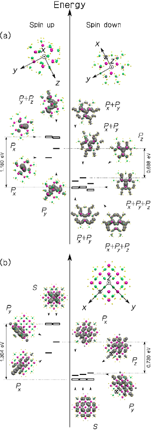
It should be clear from the previous discussion of Mn in GaN quantum dots that for ferromagnetic Mn spins the so-called Mn hole levels must be close to the GaAs valence states. Indeed, the local densities of states projected onto the Mn 3 states in Fig. 11 show that the Mn holes in GaAs nanoparticles are close together in the nearby of the valence region. These Mn holes behave hence as in bulk (Ga,Mn)Asd (2004) and mediate the ferromagnetic alignment of the two Mn spins.
Looking at the Mn hole levels in its relation to the valence (conduction) region, we can see a ferromagnetic (antiferromagnetic) behavior of Mn impurities in doped nanostructures. The difference in this hole position must be found in the smaller bond compression around Mn for (Ga,Mn)As quantum dots.
VI Conclusions
In summary, we have investigated wurtzite and zinc-blende (Ga,Mn)N quantum dots doped with one or two substitutional Mn impurities within density functional theory. We have obtained that wurtzite and zinc-blende structures show similar results as they cannot be distinguished up to second neighbors. Anyhow, there are small differences between them commented in the text when appropiate. For a single Mn dopant in the dot center, the calculated values are larger than in bulk (Ga,Mn)N with similar Mn concentration. For two Mn dopants, the most stable magnetic state is antiferromagnetic, and this was unexpected since bulk (Ga,Mn)N exhibits ferromagnetism in the ground state. We ascribe this surprising effect in (Ga,Mn)N nanoparticles to the holes linked to the Mn impurities placed close to surface. These holes do not contribute effectively to the ferromagnetic order of the two Mn spins. We show that the ferromagnetic behavior of bulk (Ga,Mn)N can be changed by reducing the crystal size.
From the antiferromagnetic result on small (Ga,Mn)N nanoparticles, it seems possible that larger dots and other nanostructures such as thin films with Mn dopants close to surface could also be antiferromagnetic in the ground state. Therefore, we hope that our results concerning antiferromagnetic (Ga,Mn)N quantum dots will encourage further ab-initio calculations and experiments on Mn impurities buried near surfaces of semiconductor nanostructures. Indeed, recent in-progress work on (Ga,Mn)N nanolayers suggests the same antiferromagnetic behavior for Mn spins.
Acknowledgements.
This work was supported by the Basque Government through the NANOMATERIALS project (Grant No. IE05-151) under the ETORTEK Program (iNanogune), the Spanish Ministerio de Ciencia y Tecnología of Spain (Grant Nos. TEC2007-68065-C03-03 and Fis2007-66711-C02-02, and MONACEM project), and the University of the Basque Country (Grant No. IT-366-07). The computing resources from the Donostia International Physics Center and the SGI-SGIKerUPV are gratefully acknowledged.References
- Orton and Foxon (1998) J. W. Orton and C. T. Foxon, Rep. Prog. Phys. 61, 1 (1998).
- Widmann et al. (1998) F. Widmann, B. Daudin, G. Feuillet, Y. Samson, J. L. Rouvière, and N. Pelekanos, J. Appl. Phys. 83, 7618 (1998).
- Bhaviripudi et al. (2007) S. Bhaviripudi, J. Qi, E. L. Hu, and A. M. Belcher, Nano Lett. 7, 3512 (2007).
- Mićić et al. (1999) O. I. Mićić, S. P. Ahrenkiel, D. Bertram, and A. J. Nozik, Appl. Phys. Lett. 75, 478 (1999).
- Wang and Herron (1990) Y. Wang and N. Herron, Phys. Rev. B 42, 7253 (1990).
- Wang and Herron (1991) Y. Wang and N. Herron, J. Phys. Chem. 95, 525 (1991).
- Albe et al. (1998b) V. Albe, C. Jouanin, and D. Bertho, Phys. Rev. B 57, 8778 (1998b).
- Albe et al. (1998a) V. Albe, C. Jouanin, and D. Bertho, Phys. Rev. B 58, 4713 (1998a).
- Pérez-Conde and Bhattacharjee (1999) J. Pérez-Conde and A. K. Bhattacharjee, Solid State Commun. 110, 259 (1999).
- Sapra and Sarma (2004) S. Sapra and D. D. Sarma, Phys. Rev. B 69, 125304 (2004).
- Echeverría-Arrondo et al. (2008) C. Echeverría-Arrondo, J. Pérez-Conde, and A. K. Bhattacharjee, J. Appl. Phys. 104, 044308 (2008).
- Biswas et al. (2006) K. Biswas, K. Sardar, and C. N. R. Rao, Appl. Phys. Lett. 89, 132503 (2006).
- Das et al. (2003) G. P. Das, C. N. R. Rao, and P. Jena, Phys. Rev. B 68, 035207 (2003).
- d (2004) M. Wierzbowska, D. Sánchez-Portal, and S. Sanvito, Phys. Rev. B 70, 235209 (2004).
- Hynninen et al. (2006) T. Hynninen, H. Raebiger, J. von Boehm, and A. Ayuela, Appl. Phys. Lett. 88, 122501 (2006).
- Hynninen et al. (2006) S. Dhar, O. Brandt, A. Trampert, L. Däweritz, K. J. Friedland, K. H. Ploog, J. Keller, B. Beshoten, and G. Güntherodt, Appl. Phys. Lett. 82, 2077 (2003).
- Hynninen et al. (2006) M. Zaja̧c, J. Gosk, G. Grazanka, M. Kamińska, A. Twardowski, B. Strojek, T. Szyszko, and S. Podsiadło, J. Appl. Phys. 93, 4715 (2003).
- Norris et al. (2001) D. J. Norris, N. Yao, F. T. Charnock, and T. A. Kennedy, Nano Lett. 1, 3 (2001).
- Besombes et al. (2004) L. Besombes, Y. Leger, L. Maingault, D. Ferrand, H. Mariette, and J. Cibert, Phys. Rev. Lett. 93, 207403 (2004).
- Hofmann et al. (2007) A. Hofmann, C. Graf, C. Boeglin, and E. Rühl, ChemPhysChem. 8, 2008 (2007).
- d (2004) J. Schneider, W. Wilkening, M. Baeumler, and F. Köhl, Phys. Rev. Lett. 59, 240 (1987).
- Raebiger et al. (2004) H. Raebiger, A. Ayuela, and R. M. Nieminen, J. Phys.: Condens. Matter 16, L457 (2004).
- Raebiger et al. (2005) H. Raebiger, A. Ayuela, and J. von Boehm, Phys. Rev. B 72, 014465 (2005).
- Marcet et al. (2006) S. Marcet, D. Ferrand, S. Kuroda, E. Gheeraert, R. M. Galera, J. Cibert, and H. Mariette, Mater. Sci. Eng. B 126, 240 (2006).
- Moreno et al. (2002) M. Moreno, A. Trampert, B. Jenichen, L. Däweritz, and K. H. Ploog, J. Appl. Phys. 92, 4672 (2002).
- Janik (2005) J. F. Janik, Powder Tech. 152, 118 (2005).
- Gosk et al. (2006) J. B. Gosk, M. Drygaś, J. F. Janik, M. Palczewska, R. T. Paine, and A. Twardowski, J. Phys. D: Appl. Phys. 39, 3717 (2006).
- Kresse and Hafner (1993) G. Kresse and J. Hafner, Phys. Rev. B 47, 558 (1993).
- Kresse and Furthmüller (1996) G. Kresse and J. Furthmüller, Phys. Rev. B 54, 11169 (1996).
- Kresse and Joubert (1999) G. Kresse and D. Joubert, Phys. Rev. B 59, 1758 (1999).
- Perdew et al. (1996) J. P. Perdew, K. Burke, and M. Ernzerhof, Phys. Rev. Lett. 77, 3865 (1996).
- Kresse and Joubert (1999) I. V. Solovyev and P. H. Dederichs, Phys. Rev. B 49, 6736 (1994).
- d (2003) B. Sanyal, O. Bengone, and S. Mirbt, Phys. Rev. B 68, 205210 (2003).
- Kresse and Joubert (1999) J. Kang and K. J. Chang, J. Appl. Phys. 102, 083910 (2007).
- Kresse and Joubert (1999) L. Liu, P. Y. Yu, Z. Ma, and S. S. Mao, Phys. Rev. Lett. 100, 127203 (2008).
- Kresse and Joubert (1999) J. A. Chan, J. Z. Liu, H. Raebiger, S. Lany, and A. Zunger, Phys. Rev. B 78, 184109 (2008).
- d (2003) We note that other corrections to GGA such as the self-interaction correction would lead to similar Mn states.d (2003, 2004, 2006, 2006)
- d (2004) J. H. Park, S. K. Kwon, and B. I. Min, Physica B 281&282, 703 (2000).
- Huang et al. (2005) X. Huang, E. Lindgren, and J. R. Chelikowsky, Phys. Rev. B 71, 165328 (2005).
- Huang et al. (2005) Y. Zhao, Y.-H. Kim, M.-H. Du, and S. B. Zhang, Phys. Rev. Lett. 93, 015502 (2004).
- Huang et al. (2005) M. C. Qian, C. Y. Fong, W. E. Pickett, and H.-Y. Wang, J. Appl. Phys. 95, 7459 (2004).
- Huang et al. (2005) S. K. Bhattacharya and A. Kshirsagar, Eur. Phys. J. D 48, 355 (2008).
- Huang et al. (2005) C. Echeverría-Arrondo, J. Pérez-Conde, and A. Ayuela, Appl. Phys. Lett. 95, 043111 (2009).
- Fatah et al. (1994) J. M. Fatah, J. Piorek, P. Harrison, T. Stirner, and W. E. Hagston, Phys. Rev. B 49, 10341 (1994).
- Echeverría-Arrondo et al. (2009) C. Echeverría-Arrondo, J. Pérez-Conde, and A. Ayuela, Phys. Rev. B 79, 155319 (2009).
- Schmidt et al. (2006) T. M. Schmidt, P. Venezuela, J. T. Arantes, and A. Fazzio, Phys. Rev. B 73, 235330 (2006).
- Larson et al. (1988) B. E. Larson, H. K. Carlsson, and H. Ehrenreich, Phys. Rev. B 37, 4137 (1988).
- d (1979) J. A. Gaj, R. Planel, and G. Fishman, Solid State Commun. 29, 435 (1979).
- d (1983) A. K. Bhattacharjee, Phys. Rev. B 58, 15660 (1998).
- Norberg and Gamelin (2006) N. S. Norberg and D. R. Gamelin, J. Appl. Phys. 99, 08M104 (2006).
- m (2007) P. L. Archer, S. A. Santangelo, and D. R. Gamelin, Nano Lett. 7, 1037 (2007).
- Bhattacharjee et al. (1983) A. K. Bhattacharjee, G. Fishman, and B. Coqblin, Physica B & C 117-118, 449 (1983).
- Merad et al. (2006) A. E. Merad, M. B. Kanoun, and S. Goumri-Said, J. Magn. and Magn. Mater. 302, 536 (2006).
- Bhattacharjee and Pérez-Conde (2003) A. K. Bhattacharjee and J. Pérez-Conde, Phys. Rev. B 68, 045303 (2003).
- d (1987) T. Chanier, M. Sargolzaei, I. Opahle, R. Hayn, and K. Koepernik, Phys. Rev. B 73, 134418 (2006).
- d (1987) Y. Shapira and N. F. Olivera, Jr., Phys. Rev. B 35, 6888 (1987).
- d (1987) C. A. Stowell, R. J. Wiacek, A. E. Saunders, and B. A. Korgel, Nano Lett. 3, 1441 (2003).
- d (1987) P. Sati, C. Depais, C. Morhain, S. Schäfer, and A. Stepanov, Phys. Rev. Lett. 98, 137204 (2007).
- d (1987) M. A. White, S. T. Ochsenbein, and D. R. Gamelin, Chem. Mat. 20, 7107 (2008).
- d (1987) O. D. D. Couto Jr., M. J. S. P. Brasil, F. Likawa, C. Giles, C. Adriano, J. R. R. Bortoleto, M. A. A. Pudenzi, H. R. Gutierrez, and I. Danilov, Appl. Phys. Lett. 86, 71906 (2005).
- d (1987) J. Sadowski, E. Janik, E. Lusakowska, J. Z. Domagala, S. Kret, P. Dlużewski, M. Adell, J. Kanski, L. Ilver, R. Brucas, and M. Hanson, Appl. Phys. Lett. 87, 263114 (2005).
- d (1987) A. Kwiatkowski, D. Wasik, M. Kamińska, J. Borysiuk, R. Bożek, J. Sadowski, and A. Twardowski, J. Mater. Sci.: Mater. Electron. 19, 740 (2008).
- d (2006) A. Filippetti, N. A. Spaldin, and S. Sanvito Chem. Phys. 309, 59 (2005).
- d (2006) M. Toyoda, H. Akai, K. Sato, and H. Katayama-Yoshida, Phys. Stat. Sol. C 3, 4155 (2006).