Spontaneous Symmetry Breaking in Two Coupled Nanomechanical Electron Shuttles
Abstract
We present spontaneous symmetry breaking in a nanoscale version of a setup prolific in classical mechanics: two coupled nanomechanical pendulums. The two pendulums are electron shuttles fabricated as nanopillars dvs_apl04 and placed between two capacitor plates in a homogeneous electric field. Instead of being mechanically coupled through a spring they exchange electrons, i.e. they shuttle electrons from the source to the drain ’capacitor plate’. Nonzero DC current through this system by external AC excitation is caused via dynamical symmetry breaking. This symmetry-broken current appears at sub- and superharmonics of the fundamental mode of the coupled system.
pacs:
45.80.+r,85.85.+j,77.65.-jSpontaneous symmetry breaking is one of the fundamental ideas in elementary particle physics when unified gauge field theories are applied weinberg , e.g. breaking the gauge symmetry leads to the difference in the electromagnetic and the weak interaction. Commonly, one refers to a classical mechanics example to visualize symmetry breaking, such as a thin bar under pressure from both its clamping points. Obviously, the equations of motion are invariant around the symmetry axis along the beam. Once the force reaches a critical level the compressed bar will buckle and thus break the initial symmetry. Although, in the buckled state the bar will be in an energetic minimum, the symmetry of this configuration is reduced. From a quantum mechanical point of view the key question is into which of the many degenerate energetic minima the compressed bar will collapse to and what kind of fluctuation will have caused this transition. Naturally, for a large bar governed by classical mechanics it would be hard to associate the buckling with quantum mechanical states. The situation changes drastically when one considers quantum electro-mechanical systems (QEM) blencowe , such as buckled nanomechanical beams which have been theoretically discussed by Carr et al. carr . In other words nanomechanical devices have the potential to address fundamental quantum mechanics craighead ; karrai ; naik ; steele .
In the following we will present electron transport measurements via two coupled electron shuttles at room temperature under AC/DC excitation. The two shuttles we fabricated have the same physical dimensions, are isolated from ground, and possess metallic tips. The actual realization of the device is shown in the scanning electron microscope graph in Fig. 1(a): the two nanopillars forming the shuttles are placed in series between source and drain contacts. The diameters of the islands on top of each nanopillar is 65 nm with pillar heights of 250 nm. The inter-pillar distance is 17 nm and is much less than the gaps to source and drain, enhancing mode coupling. The distance from source to the first pillar and drain to the second one are identical, making the setup indeed very symmetric. Our particular focus will be on how breaking the local symmetry leads to the rectified current as recently conjectured by Ahn et al. ahn . The fundamental outcome is that although both the nanomechanical and the nanoelectronic circuits are operated in the linear regimes an AC voltage can be rectified. Commonly, rectification only occurs based on a nonlinearity, however, such symmetry breaking in coupled nanomechanical pendulums is exactly what is predicted in Ref. ahn .
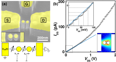
The two nanopillars are milled out of a silicon-on-insulator (SOI) material, where the top crystalline silicon is 190 nm thin and the insulating SiO2 is about 350 nm thick. A 50 nm top gold layer serves as the electrical conduction path. The deposited metal serves as an etch mask in a dry etch step which mills out the SOI material around the pillars. We apply a CF4 plasma etch step and etch into the SiO2 insulating layer, thus ensuring electron transport via the metallic islands (further processing details are given in Ref. hskim07 ). The nanoscale circuit is placed in an impedance matched transmission line in order to minimize signal loss along the line. All measurements are performed under vacuum in a probe station at room temperature. The station is placed in a Faraday cage and is equipped with radio frequency contact probes covering the range from DC to 50 GHz ( a bias-tee allows AC/DC superposition with high precision). The equivalent circuit diagram is given in the lower part of Fig. 1(a): the two pillars can be individually displaced by and , which lead to tunable resistances and capacitances (arrow boxes).
In the first measurement we trace the direct current at different voltage bias values at room temperature as shown in Fig. 1(b). At first glance the -characteristic appears to be linear with only a small deviation () at above 1 V. Electron shuttling is leading to the non-zero current, which is caused by self-excitation (SE) as we have shown earlier for single nanopillars hskim09 . This can also be shown for lateral electron shuttles dvs_apl04 ; koenig . In this particular case we assume that several mechanical modes of the coupled nanopillars (see below in Fig. 2) support the current. The ease of excitation is supported by the finite-element numerical simulation shown in the inset of Fig. 1(b). Obviously, the electric field intensity is dramatically enhanced around the two pillars, enabling the onset of mechanical oscillations under an applied DC bias voltage. Closer inspection of the low-voltage regime reveals the onset of Coulomb blockade (CB) in these serially coupled electron shuttles, as predicted by Gorelik et al. gorelik98 . The dashed lines in the inset indicate the individual Coulomb staircase, which is getting weaker towards voltages above 100 mV. A brief investigation of the trace reveals that the CB charging energy is of the order of the room temperature energy at 26 meV. Since we are operating the coupled shuttles at large AC-voltage swings ( mV amplitude) as compared to the thermal background ( mV), we can focus on the overall linear -characteristic. For all measurements presented here the gate voltage potential was left at ground.
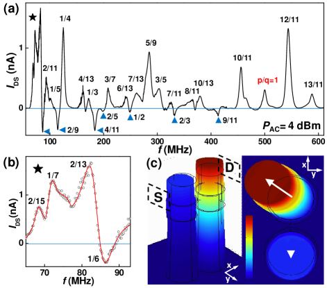
A radio frequency signal in the range of 1 MHz to 1 GHz is applied via high-frequency probes in order to trace the mechanical spectrum of the coupled nanopillars, similar to earlier work on single nanopillars dvs_apl04 ; hskim07 . The resulting output current from the coupled electron shuttles is a time-averaged DC signal leading to the spectrum shown in Fig. 2. The DC response of the coupled shuttles to the AC excitation is plotted at a DC bias voltage of mV. A broad set of resonances can be identified representing different modes of the coupled nanopillars. On closer inspection of the overall spectrum we find that the multitude of peaks arises due to a parametric instability caused by dynamical symmetry breaking, as predicted by Ahn et al. ahn . The ratios noted at each peak follow with being integers. From finite element simulations we find that the most likely fundamental mode of the coupled nanopillars is at around MHz at , see Fig. 2(a). Unlike the theoretical prediction ahn , we find both even and odd numbers for . The hierarchy of resonances is also slightly different from the theoretical result in that the current spectrum of the coupled electron shuttles has a richer structure with higher orders for . We can attribute these differencies to more degrees of freedom in the real device allowing mechanical modes in all three spatial dimensions.
With increasing external AC power we observe peak broadening, overlaping with neighboring peaks. We find the modes with the winding numbers, generated by ’Farey sums’ of neighboring modes’ fractions when overlapping on the left and right: The numerator is the sum of the numerators of the fractions on either side, and the denominator is the sum of the denominators of the fractions on either side farey1 . For instance, and so on. A similar behavior was observed in nonlinear systems showing structure of Arnold tongues farey2 . The appearance of fractions of the fundamental mode and Farey trees with neighboring modes’ fractions indicate that we detect dynamical symmetry breaking.
Most peaks of the spectrum show a forward current, as one expects under forward bias, while some of the peaks give a reverse current(blue triangles). This remarkable feature of the coupled shuttles, i.e. reverse shuttling or pumping, marks a bistability depending on initial conditions, such as positions and velocities of two islands at a given time. We need to note, as will be underlined theoretically below, that the resulting rectified current at zero bias observed here is solely due to a dynamical symmetry breaking and not by a mechanical or electronic nonlinearity. In detail the resonance shapes of the two-nanopillar system are analyzed in Fig. 2(b): a magnified part of the spectrum at below 100 MHz is shown with three fits (red lines) indicating the different line shapes. The resonance around 69 MHz follows the conventional Lorentzian, while the trace at 84 MHz shows a maximum and minimum.
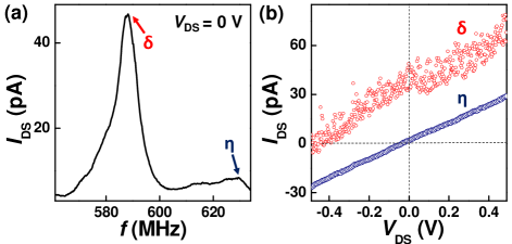
We now turn to the details of the rectification effect due to symmetry breaking: as an example we select the pronounced resonance at . The particular peak around 589 MHz is plotted in Fig. 3(a) and marked as . The off-resonance background is labeled with . In Fig. 3(b) the -traces for these two frequency points are given: as expected for the background the -line shows a linear dependence crossing through the origin of the graph. In contrast the -trace reveals a clear offset under finite AC excitation at 589 MHz. This motion of the coupled charge shuttle indicates the existence of a bifurcation point ahn .
The theoretical underpinning for this bifurcation of the coupled shuttle leads to the rectified current ahn . A sinusoidal electromagnetic excitation is applied to the source contact, inducing mechanical displacement of the shuttle at their eigenfrequencies. We can assume that the capacitances between the electrodes are constant, while the tunneling resistance varies with electrode distance as , where is the tunneling length. The refer to the three junctions () in series, i.e. from source to the first nanopillar, in between the pillars, and finally from the second pillar towards drain. The coupled nanopillars can be assumed to show a linear response under modest excitation as measured in Fig. 1(b) leading to a mechanical displacement, which can be described by a differential equation in the adiabatic limit ahn
| (1) |
where is the relative coordinate, , denote the friction coefficient and the natural angular frequency of the shuttles, gives the nanopillars mass, and is the source-drain distance. There is a pair of bistable solutions, and . The time-averaged direct current is found to be
| (2) |
where we assume a symmetric configuration: . For a single nanopillar with a symmetric source-drain the direct current with AC input voltage will always average out to zero, making the above integral zero. However, for two coupled nanopillars the symmetry will be broken leading to a DC signal as we observe in Fig. 3(b). We note that this current only can be found for two coupled nanopillars.
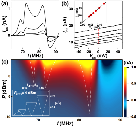
In order to further verify the dynamical symmetry breaking and the resulting rectification we determined the AC power dependence of the low-frequency end at around 80 MHz, revealing the expected Arnold tongues arnold . Fig. 4(a) shows the detailed power dependence of the output current with line plots with the power level increasing from -10 dBm to +4 dBm. In Fig. 4(b) the maximal current at 83 MHz is plotted vs. DC bias and AC power ramped up as the parameter. The inset gives the scaling of generated direct current with respect to applied AC-power, indicating the rectification. In Fig. 4(c) finally the total power dependence is shown in a color scale plot: the boundaries of each tongue are seen. The experimental bifurcation diagram shows the gradual appearance of higher order resonances as the input power increases. The thin dashed lines trace the increase in width as expected for Arnold’s tongues. The appearance of Arnold’s tongues is also observed in mathmatical simulations of two charge shuttles coupled via electron tunneling as discussed in Ref. ahn . In each bistable region the fundamental mode and the external excitation are mode-locked in spite of the frequency mismatch. Devil’s staircase depicts winding numbers of the mode-locked regions, as shown in the inset of Fig. 4(c). This staircase maps the widths of the Arnold’s tongues, defined as the FWHM for a given power of AC excitation. Even though this two pillar system does not have a perfect left-right symmetry, driving the enhanced net current was possible due to the robustness of the observed mode locking.
In summary we find dynamical symmetry breaking in coupled linear nanopillars traced in the current response of the pillars to an AC excitation. The identified resonances were agreed with the theoretical expectation by ahn except for some discrepanies due to the three-dimensional nature unlike the calculation model. The power dependance manifests the Arnold tongue structure where the bistability of the system allows for nonzero currents. This setup has potential as a bifurcation amplifier for signal processing applications bif_amp and can prove to be useful for energy scavenging applications rectenna .
Acknowledgements – The authors like to thank DARPA for support through the NEMS-CMOS program (N66001-07-1-2046) and the Graduate School of the University of Wisconsin-Madison for support through a Draper-TIF award.
References
- (1) D. V. Scheible and R. H. Blick, Appl. Phys. Lett. 84, 4632 (2004).
- (2) S. Weinberg, Rev. Mod. Phys. 46, 255 (1974).
- (3) M. Blencowe, Phys. Rep. 395, 159 (2004).
- (4) S. M. Carr, W. E. Lawrence, M. N. Wybourne, Phys. Rev. B 64, 220101(R) (2001).
- (5) H. G. Craighead, Science 290, 1532 (2000).
- (6) C. H. Metzger and K. Karrai, Nature 432, 1002 (2004).
- (7) A. Naik et al., Nature 443, 193 (2006).
- (8) G. A. Steele et al., Science 325, 1103 (2009).
- (9) K. H. Ahn, H. C. Park, J. Wiersig and J. Hong, Phys. Rev. Lett. 97, 216804 (2006).
- (10) H. S. Kim, H. Qin, R. H. Blick, Appl. Phys. Lett. 91, 143101-03 (2007).
- (11) H. S. Kim, H. Qin, R. H. Blick, New Journal of Physics, in press (2010).
- (12) D. R. Koenig, E. M. Weig and J. P. Kotthaus, Nature Nanotechnology 3, 482 (2008).
- (13) L. Y. Gorelik et al., Phys. Rev. Lett. 80, 4526 (1998).
- (14) P. Cvitanović, M. H. Jensen, L P. Kadanoff, I. Procaccia, Phys. Rev. Lett. 55, 343 (1985).
- (15) J. A. Glazier, M. H. Jensen, A. Libchaber, J. Stavans, Phys. Rev. A 34, 1621 (1986).
- (16) S.-B. Shim, M. Imboden, P. Mohanty, Science 316, 95 (2007).
- (17) R. Almog,S. Zaitsev, O. Shtempluck, E. Buks, Phys. Rev. Lett. 98, 078103 (2007).
- (18) J. A. Hagerty, F. B. Helmbrecht, W. H. McCalpin, R. Zane, Z. B. Popovic, IEEE Trans. MTT 52, 1014 (2004).