Fundamental Gates for a Strongly Correlated Two-Electron Quantum Ring
Abstract
We demonstrate that conditional as well as unconditional basic operations which are prerequisite for universal quantum gates can be performed with almost 100% fidelity within a strongly interacting two-electron quantum ring. Both sets of operations are based on a quantum control algorithm that optimizes a driving electromagnetic pulse for a given quantum gate. The demonstrated transitions occur on a time scale much shorter than typical decoherence times of the system.
pacs:
85.35.Be, 03.67.-a ,78.67.-nQuantum computing requires a set of fundamental single-qubit operations which can address and manipulate each qubit regardless of the state of the others. In addition at least one conditional operation must be defined which can address any chosen qubit based on the status of another Barenco et al. (1995). This poses a major challenge in all logical devices composed of strongly interacting single particle qubits: The interaction then creates entangled multi-particle states which hide the single particle character completely, e.g. regarding the energy spectrum or the spatial particle distribution. Nevertheless, several basic operations and quantum information algorithms have been demonstrated, in nuclear magnetic resonances Chuang et al. (1998), trapped ions Cirac and Zoller (1995) and coupled superconducting Josephson junctions Chow et al. (2009), but scalability and decoherence remain severe obstacles in taking experiments from a demonstration level to manipulation of a large number of qubits.
The original idea to build gates from coupled quantum dots by Loss and DiVincenzo Loss and DiVincenzo (1998) was based on single electron spin states interacting in neighboring dots. Recently Petta et. al. Petta et al. (2005) demonstrated single qubit control using the total spin state of a two-electron quantum dot molecule. Conditional operations in coupled quantum dots have also been experimentally demonstrated Robledo et al. (2008), where excited states are a part of the information carrier. Another suggestion has been to include two qubits in a single quantum dot molecule with the total spin as one qubit and charge localization as the other Hanson and Burkard (2007).
Relative to coupled quantum dot-molecules and quantum dot-arrays, the quantum-ring structure possesses a high-degree of symmetry, implying the existence of conserved quantities, e.g. persistent currents Chakraborty and Pietiläinen (1994), related to the conservation of total electron angular momentum. The use of conserved quantities for the buildup of a quantum processor may be advantageous, compared to e.g. charge localized states, since the former are time-independent as long as weak decoherence mechanisms, such as spin-orbit or hyperfine interactions, can be neglected. In compliance with this we recently proposed the two-electron quantum ring total angular momentum and total electron spin as a pair of independent qubits Waltersson et al. (2009). Since the total angular momentum is truly multivalued, we coined this system a “quMbit”.
In this Letter we show that the total orbital angular momentum and the total electron spin in the two-electron quantum ring, in spite of the strong electron-electron interaction, can be coherently and independently manipulated and that the intended quantum state is obtained with almost 100% probability. Hereby successful gate operations are achieved, for both the unconditional (NOT) and the conditional (CNOT) inversion operation. An alternative route to scalability can then be foreseen since the information content of each quantum ring increases with the number of controllable states. After a short introduction we demonstrate conditional and unconditional manipulations of the angular momenta and finally the unconditional manipulations of the spin are outlined.
The confinement of an electron in a 2D quantum ring is modeled by a displaced harmonic potential rotated around the -axis, giving a two-electron Hamiltonian
| (1) |
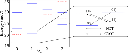
Here is the effective mass ( for GaAs), determines the confinement strength, is the radial coordinate for each particle, is the ring radius and is the relative dielectric constant ( for GaAs). We have varied the ring parameters around the values used in experiments Lorke et al. (2000) to optimize the gate performances and settled for a.u. nm and a potential strength of meV, which have been used throughout this work. The eigenvectors and eigenvalues of the Hamiltonian (1) are found by exact diagonalization Waltersson and Lindroth (2007). Fig. 1 shows the energy spectrum (left), where red dashed lines denote triplet states, , and blue solid lines denote singlet states, . The right panel shows the two pairs of states that constitute our gates and the transitions to be controlled: The NOT gate is a logical negation operation which inverts (switches) the state of the qubit. Solid gray arrows indicate such a switch of the orbital angular momentum independently of the spin state. The controlled NOT (CNOT) gate is indicated by a single black (dashed) arrow. It changes the orbital angular momentum state for a spin triplet state, but leaves it unaffected for a singlet. Hence, for this operation, the spin state is the control bit and the angular momentum is the target bit.
To induce the needed transitions between the different eigenstates of (1), the ring is exposed to an electromagnetic pulse, an adiabatically varied homogeneous magnetic field in the -direction, , and a weak inhomogeneous magnetic field, ,
| (2) | |||||
resulting in a time dependent Hamiltonian . The electric field drives the angular momentum CNOT- and NOT gate operations, while the two magnetic fields are needed to perform the unconditional spin flip. The inhomogeneous field is typically several orders of magnitude weaker than and is omitted in the diamagnetic term. Through quantum control algorithms Räsänen et al. (2007); Sælen et al. (2008), the electric pulse can be optimized with respect to the desired gate operation.
Numerical solutions of the time dependent Schrödinger equation were recently used to show that a CNOT operation could be realized with % fidelity for a transition Waltersson et al. (2009). For this a circularly polarized electric field pulse, was driving the transition between the two qubit levels, cf. Fig. 1. The transition was realized with a central frequency, , corresponding to the energy difference between the active states, within a transition time a.u. ps and with an intensity a.u.∗ W/cm2. By optimizing the transition using two independent electric fields in the and direction we obtain a significant improvement in fidelity as well as a shorter transition time. The electric field is defined as a set of piecewise constant functions on the divided time interval, , . During the time propagation of the system wavefunction, , the field components are adjusted at each step according to a first order scheme Krotov (1996), e.g. for the x-component
| (3) |
and similarly for the y-component. In (3) is the iteration number, and is the solution to the Schrödinger equation with termination condition . We want to maximize the projection (the yield), . The only constraint in this simple scheme is an energy penalty given by the parameter favoring low intensity fields. Additional penalties on the structure and derivative of the control fields can be implemented to increase the fidelity even further Nepstad et al. (2009). Here we utilized this possibility for the CNOT. Through optimization with respect to final states for both the singlet and the triplet systems simultaneously, we are in addition able to achieve very high yields for the complete CNOT gate as well as for the unconditional angular momentum flip. The optimization in the former case is done starting in the triplet and singlet states, , and using the combined target state, . Similarly for the unconditional angular momentum flip; we start in the singlet and triplet states and optimize with respect to the target state . This requires complete transitions for two separate energy differences, implying a more complex driving field, with at least two central frequencies.
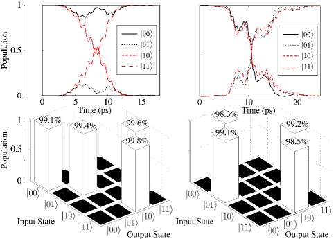
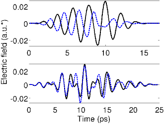
Fig. 2 shows the transition dynamics with initial population for the two operations, the controlled NOT gate to the left, and the unconditional NOT gate to the right. The upper figures show the population of the qubits during the pulse. For the CNOT operation the initial state is seen to steadily decay transferring probability to the state, and eventually we observe a complete transition. The initial singlet state, , on the other hand is transiently coupled to other states but recovers its initial population at the end of the pulse. Correspondingly, the upper right panel shows a nearly complete transition from to for both spin states. An important gate condition is that the operations should work also in the opposite directions, e.g. for the CNOT operation the same pulse should transfer initial population in to while leaving the singlet state population unaltered. The lower panels of Fig. 2 show the truth tables after the completed operation for both initial conditions. The transition yields are seen to be for the NOT gate and for the CNOT gate, within transition times as short as ps and ps respectively, i.e. three orders of magnitude faster than the inverse of the typical electron-acoustical phonon scattering rates in GaAs-structures Climente et al. (2006). For the opposite transitions the yields are slightly lower but all still . For other linear combinations, e.g. an initial entangled state , imperfections are found to be less than . These results are achieved within as few as 10 iterations of the type in Eq. (3). Fig. 3 shows the optimized pulses for the CNOT and NOT gates decomposed in and components. The pulses are rather simple, with frequency spectra centered around the energy of the resonance transitions.
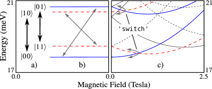
Finally, we consider unconditional manipulations of the spin. This requires inhomogeneous magnetic fields or other spin-mixing interactions. In principle an optimization algorithm as above could be used, simply switching spin with angular momentum. However, present technology cannot realistically deliver inhomogeneous fields stronger than the regime across the quantum ring system. We propose therefore a two step procedure involving combined homogeneous and inhomogeneous fields, illustrated in Fig. 4. Consider the transition from to , i.e. from the lower singlet state (solid blue curve) to the upper triplet state (dashed, red curve). The right panel shows the energy levels in the presence of a homogeneous magnetic field, obtained by diagonalization of the Hamiltonian (1) in the presence of the terms in (2). The field can bring the -state adiabatically to the crossing point with the triplet state . Here the spin is flipped by application of an inhomogeneous magnetic field over the ring. When the homogeneous field is subsequently decreased it is evident that the transition has been made to the ’wrong’ triplet state, see Fig. 4. To make the final transition to the required triplet state we simply apply the unconditional NOT as demonstrated in Fig. 2. The unconditional spin flip operation thus becomes,
| (4) |
where and are time evolution operators, of which the order is arbitrary. If the inhomogeneous magnetic switch is applied at both avoided crossings (curved arrows) the scheme will flip the spin state regardless of initial state.
The adiabatic development with homogeneous external magnetic fields is well known and the detailed dynamics of the spin flip transition is now outlined: From decoherence studies it is known that a weak inhomogeneous magnetic field can flip the spin state of the system. The strength of the magnetic fields is in these cases typically a few mT Petta et al. (2005); Nepstad et al. (2008). With an inhomogeneous magnetic field mT, the spin flip can be performed on a much shorter timescale than the natural process. Notably, it has been proposed to selectively flip the spin by making use of the Aharonov-Bohm effect in quantum rings Frustaglia et al. (2001).
The two spin states can, with a circular configuration,
| (5) |
form a local two-level system. In the adiabatic basis the dynamics at the avoided crossings is described by,
| (6) |
where denotes the amplitude of the two (avoided) crossing spin states and is the coupling induced by the inhomogeneous field. The spin flip is then realized as a perfect rotation around the z-axis (on the Bloch sphere) within a time frame, .
In conclusion we have demonstrated conditional and unconditional fast high fidelity quantum gates in a strongly coupled two-electron quantum ring model. We remark that the fidelity of each gate may be further improved by restricting the upper intensity of the controlling fields on the expense of transition times. Alternatively it may be increased with fixed intensities and reduced system sizes. Storage and control of quantum information has thus been shown for two-level spin states entangled with potential multivalued angular momentum states. An extension of the qubit to a multibit may be achieved through introduction of higher excitation levels within each angular momentum number. The proposal rests on the ability to steer the system between initial and final states with close to transition probability. This has indeed been achieved with relatively simple final pulse shapes.
We acknowledge support from the Norwegian Research Council, the Swedish Research Council (VR) and from the Göran Gustafsson Foundation.
References
- Barenco et al. (1995) A. Barenco, C. H. Bennett, R. Cleve, D. P. DiVincenzo, N. Margolus, P. Shor, T. Sleator, J. A. Smolin, and H. Weinfurter, Phys. Rev. A 52, 3457 (1995).
- Chuang et al. (1998) I. L. Chuang, L. M. K. Vandersypen, X. Zhou, D. W. Leung, and S. Lloyd, Nature 393, 143 (1998).
- Cirac and Zoller (1995) J. I. Cirac and P. Zoller, Phys. Rev. Lett. 74, 4091 (1995).
- Chow et al. (2009) J. M. Chow, J. M. Gambetta, L. S. Bishop, B. R. Johnson, D. I. Schuster, J. M. A. Blais, L. Frunzio, S. M. Girvin, and R. J. Schoelkopf, Nature 460, 240 (2009).
- Loss and DiVincenzo (1998) D. Loss and D. P. DiVincenzo, Phys. Rev. A 57, 120 (1998).
- Petta et al. (2005) J. R. Petta, A. C. Johnson, J. M. Taylor, E. A. Laird, A. Yacoby, M. D. Lukin, C. M. Marcus, M. P. Hanson, and A. C. Gossard, Science 309, 2180 (2005).
- Robledo et al. (2008) L. Robledo, J. Elzerman, G. Jundt, M. Atature, A. Hogele, S. Falt, and A. Imamoglu, Science 320, 772 (2008).
- Hanson and Burkard (2007) R. Hanson and G. Burkard, Phys. Rev. Lett. 98, 050502 (2007).
- Chakraborty and Pietiläinen (1994) T. Chakraborty and P. Pietiläinen, Phys. Rev. B 50, 8460 (1994).
- Waltersson et al. (2009) E. Waltersson, E. Lindroth, I. Pilskog, and J. P. Hansen, Phys. Rev. B 79, 115318 (2009).
- Lorke et al. (2000) A. Lorke, R. Johannes Luyken, A. O. Govorov, J. P. Kotthaus, J. M. Garcia, and P. M. Petroff, Phys. Rev. Lett. 84, 2223 (2000).
- Waltersson and Lindroth (2007) E. Waltersson and E. Lindroth, Phys. Rev. B 76, 045314 (2007).
- Räsänen et al. (2007) E. Räsänen, A. Castro, J. Werschnik, A. Rubio, and E. K. U. Gross, Phys. Rev. Lett. 98, 157404 (2007).
- Sælen et al. (2008) L. Sælen, R. Nepstad, I. Degani, and J. P. Hansen, Phys. Rev. Lett. 100, 046805 (2008).
- Krotov (1996) V. F. Krotov, Global Methods in Optimal Control Theory (Dekker, 1996).
- Nepstad et al. (2009) R. Nepstad, L. Sælen, I. Degani, and J. P. Hansen, J. Phys.: Condensed Matter 21, 215501 (2009).
- Climente et al. (2006) J. I. Climente, A. Bertoni, G. Goldoni, and E. Molinari, Phys. Rev. B 74, 035313 (2006).
- Nepstad et al. (2008) R. Nepstad, L. Sælen, and J. P. Hansen, Phys. Rev. B 77, 125315 (2008).
- Frustaglia et al. (2001) D. Frustaglia, M. Hentschel, and K. Richter, Phys. Rev. Lett. 87, 256602 (2001).