Localized Joule heating produced by ion current focusing through micron-size holes
Abstract
We provide an experimental demonstration that the focusing of ionic currents in a micron size hole connecting two chambers can produce local temperature increases of up to C with gradients as large as K. We find a good agreement between the measured temperature profiles and a finite elements-based numerical calculation. We show how the thermal gradients can be used to measure the full melting profile of DNA duplexes within a region of m. The possibility to produce even larger gradients using sub-micron pores is discussed.
The creation of local heat sources and large thermal gradients in confined aqueous environments is a challenging problem due to the rapid diffusion of heat in water. Several solutions were proposed, such as heating micro/nanoparticles HamadNature02 ; LevyJPCM08 by magnetic induction or by using a focused laser beam BraunePRL02 ; BaaskeAPL07 . Local thermal gradients in microchannels were used to sort and concentrate molecules. Several approaches were developed such as thermophoresis DuhrPNAS06 , Temperature Gradient Focusing RossAnalChem02 , Field Gradient Focusing KoeglerBioPro96 , and isoelectric Focusing PawliszynJMS93 ; KatesEl06 . These techniques use high DC voltages (tens to hundreds of Volts) and thermal gradients in the range of Km-1. The typical volumes are micro to nanoliters. In this letter, we show that a few tens of picoliters can be strongly heated by focusing an ionic current through a micron size hole in a saline solution. The resulting gradients are of the order of Km-1.
We use a custom made cell composed of two chambers separated by a m thick Teflon septum (see Figure 1). A conical hole ( half angle, minimum diameter m) is punctured in the center of the septum. The AC voltage (, 10 kHz) is applied across the chambers using platinum electrodes. We use tris buffer, M KCl, pH 7.4, of electrical conductance mS/cm. The DC value of the electrical resistance across the hole is . The septum capacitance is estimated to pF. It results that the current across the chambers is mostly resistive at kHz. The Joule heating power dissipated in the hole is proportional to the mean root square current . We measure the local temperature profiles along the vertical hole axis in the lower chamber. The temperature is derived from the confocal detection ( nm) of the calibrated fluorescence of TetraMethylRhodamine (TMR) grafted at the 5’end of DNA oligomers.
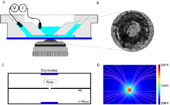
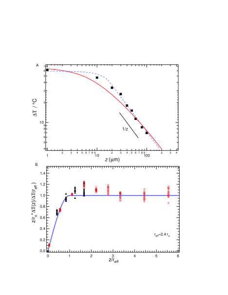
Large enough currents, mA, result buffer vaporization. Smaller values of lead to stationary thermal profiles within a few seconds. Figure 2 A shows the temperature increase , where K is the room temperature, along the vertical axis for mA. Over the first m , the average temperature gradient is Km-1. As a first approximation we model the heating power as being distributed uniformly in an effective sphere of radius . The temperature then reads:
| (1) |
where is the distance from the hole center and Wm-1K-1 is the thermal conductivity of water. Figure 2A shows the measured temperature profile for hole radius m and power W. The best fit parameters for our model are m and a W. This model predicts that when the value of is a constant independent of and . Figure 2B shows that the curves for several values of and can be scaled provided that we take .
In order to explore the influence of the pore geometry on thermal profiles we use a finite elements approach with various hole radiuses and pore lengths . The numerical calculation accounts for mass transport (2), electrostatic potential (3) and heat dissipation (4) in the following way:
| (2) | |||||
| (3) | |||||
| (4) |
, and are the number densities, the diffusion coefficients and the electrophoretic mobilities of the positive and negative ions, respectively. is the electric potential, is the local dielectric constant, is the electrical conductivity, is the electron’s charge, and is the heat capacity. The steady-state solutions were obtained with an AC voltage at the electrodes. See Supplementary Material for details.
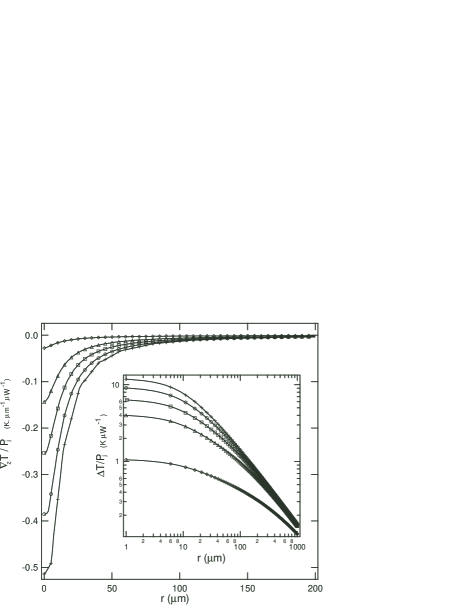
Figure 3 shows the calculated temperature and gradient profiles along the z axis at a fixed heating power for several values of the aspect ratio . When the temperature is well described by for values larger than . In the limit of small aspect ratio the heating is mainly localized in the hole and smoothly spreads in the lower chamber producing smaller temperature gradients. We conclude that should ideally be between and to obtain the sharpest gradients and largest temperature increases.
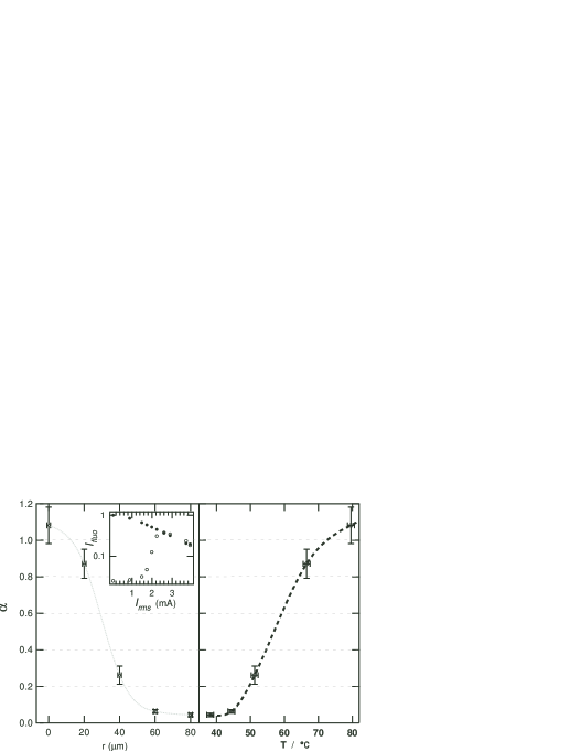
The experimental thermal gradients generated by a hole of diameter m are used to determine the melting profile a DNA duplex: strand 1: TMR ’-TCAGACCG(TC)15-’, strand 2: ’-CGGTCTGA-’ IowaBlack. The DNA was gel purified to obtain a % hybridization efficiency. The fluorescence intensity of the TMR is quenched -fold on average upon hybridization with IowaBlack. With a proper baseline calibration the fluorescence intensity measured at the laser spot can be used to determine the fraction of hybridized duplexes. We measure the fluorescence profiles at various values of for strand only, and for the hybridized duplex with a : ratio of both strands (see Figure 4). Assuming (i) a local thermal equilibrium, (ii) a two state model where the 8 mers are either fully hybridized or completely open, and (iii) an efficient quenching for all temperatures, we can extract the dissociation coefficient of the hairpin as a function of temperature and distance from the pore. Figure 4 shows the full melting profile obtained over a distance of 45 m for a hole of radius m. Following the typical melting curve analysis for bimolecular equilibrium MergnyON03 , we extract the thermodynamical melting parameters of the DNA structure. We find kCal mole-1 and Cal mole-1 K-1, in good agreement with the thermodynamical parameters calculated with MFold Mfold under similar salt conditions ( kCal mole-1 and Cal mole-1 K-1). Spatial temperature gradients have the advantage over traditional melting curves techniques that all temperatures can be probed simultaneously. This method works if the diffusion and/or drift of the DNA molecule across the thermal profile is slow enough to allow thermal equilibration. As derived in the Supplementary Material, electrophoretic and electroosmotic drifts are negligible in our experiments. The Brownian diffusion coefficient TinlandMacro97 for our DNA molecules is of order cm2s-1. The distance over which the temperature changes by is d= m. The diffusion time across this distance is s. Since small molecular beacons are reported to open over a characteristic time of s BonnetPNAS98 , the approximation of local equilibrium is satisfied.
We briefly discuss the influence of various parameters on the applicability of our device. For frequencies , where is a geometry-dependent factor, the ionic current is mostly resistive. It is reasonable to assume that electroosmotic flow are negligible due to the use of AC fields. Electroosmosis can be significantly enhanced in smaller ( nm) or charged pores when current rectification occurs Siwy06 . In the lower chamber natural convection is minimized since the hot spot (the hole) is located above the cold region. In addition, there is negligible fluid transfer between the upper and lower chambers. The small extent of the lower chamber also increases the instability threshold for natural convection. This situation contrasts with focused laser heating for which convective rolls are observed along the optical axis BraunePRL02 . Convection can be externally applied to drive the molecule through the thermal profile. Our conclusions would still hold in the limit of small Peclet numbers i.e if the convective velocity is small: m s-1. In this limit thermal quenching rate of K/s can still be achieved. See Supplementary Material for a detailed discussion. We believe that this approach facilitates the creation of large thermal gradients in sub-micron regions with potential applications for fast denaturation and thermal quenching ViasnoffNanoLett06 to study local chemical reactions.
References
- (1) K. Hamad-Schifferli, J. J. Schwartz, A. T. Santos, S. G. Zhang, and J. M. Jacobson, Nature 415, 152 (2002).
- (2) M. Levy, C. Wilhelm, J. M. Siaugue, O. Horner, J. C. Bacri, and F. Gazeau, J. Phys-Condens. Mat. 20, 204133 (2008).
- (3) P. Baaske, S. Duhr, and D. Braun, Appl. Phys. Lett. 91,133901 (2007).
- (4) D. Braun and A. Libchaber, Phys. Rev. Lett. 89, 188103 (2002).
- (5) S. Duhr and D. Braun, Proc. Natl. Acad. Sci. U.S.A. 103, 19678 (2006).
- (6) D. Ross and L. E. Locascio, Anal. Chem. 74, 2556 (2002).
- (7) W. S. Koegler and C. F. Ivory, Biotechnol. Progr. 12, 822 (1996).
- (8) J. Pawliszyn and J. Q. Wu, J. Microcolumn. Sep. 5, 397 (1993).
- (9) B. Kates and C. L. Ren, Electrophoresis 27, 1967 (2006).
- (10) J. L. Mergny and L. Lacroix, Oligonucleotides 13, 515 (2003).
- (11) http://www.bioinfo.rpi.edu/applications/mfold.
- (12) B. Tinland, A. Pluen, J. Sturm, and G. Weill, Macromolecules 30, 5763 (1997).
- (13) G. Bonnet, O. Krichevsky, and A. Libchaber, Proc. Natl. Acad. Sci. U.S.A. 95, 8602 (1998).
- (14) Z.Siwy, Adv.Funct.Mat 16, 735 (2002).
- (15) V.Viasnoff, A.Meller, and H. Isambert, Nano.Letters 6, 101 (2006).