Ionic Effects on the Electric Field needed to Orient Dielectric Lamellae
Abstract
We consider the effect of mobile ions on the applied potential needed to reorient a lamellar system of two different materials placed between two planar electrodes. The reorientation occurs from a configuration parallel to the electrodes favored by surface interactions to an orientation perpendicular to the electrodes favored by the electric field. The system consists of alternating A and B layers with different dielectric constants. The mobile ions are assumed to be insoluble in the B layers and hence confined to the A layers. We find that the ions reduce the needed voltage most strongly when they are constrained such that each A lamella is electrically neutral. In this case, a macroscopic separation of charge and its concomitant lowering of free energy, is attained only in the perpendicular orientation. When the ions are free to move between different A layers, such that charge neutrality is only required globally, their effect is smaller and depends upon the preferred surface interaction of the two materials. Under some conditions, the addition of ions can actually stabilize the parallel configuration. Our predictions are relevant to recent experiments conducted on lamellar phases of diblock copolymer films with ionic selective impurities.
I INTRODUCTION
Block copolymers are polymeric materials with specific chain architecture in which several blocks of different chemical nature are linked covalently. The simplest design is that of a di-block in which two polymeric blocks, A and B, are connected. Even in this design the system manifests a rich phase structure of self-assembled periodic arrays of spheres, cylinders, or planes, which has many applications such as templates for nanoscopic devices park97 ; walheim99 ; morkved96 ; talbrechtsci00 ; lopes01 ; park03 . One difficulty which must be overcome before block copolymer arrays can be exploited is the fact that, when produced as a thin film, the array tends to align with the substrate due to preferential interactions between it and one of the polymer blocks. In many applications, however, the desired orientation is one in which the ordered structure is aligned perpendicular to a substrate. For example, if a cylindrical array is aligned perpendicularly, then the cylinder cores can be etched away and replaced by a metal. Further removal of the material surrounding the cores produces an array of wires useful for sensors park97 . One method to bring about this orientation is to subject the film to an electric field amundson93 ; amundson94 ; morkved96 ; pereira99 ; boker02 ; tsori02 ; ashok01 , a technique which takes advantage of the difference in dielectric constants between the two polymer blocks. Because the electric field needed to produce the desired orientation can be rather high, on the order of V/m, it can happen that the material undergoes dielectric breakdown before alignment is achieved. As a way of lowering the electric field needed for alignment, Tsori et al. tsori03 suggested that one could introduce free ions into the system. Presumably if the ions were preferentially soluble in one of the blocks, the induced dipole moment of that block would become much larger in the perpendicular orientation. The increase in polarization would bring about the desired decrease in the electric field needed for alignment.
This procedure has been utilized experimentally and the desired increase in orientation obtained for a given applied field xu04 ; wang06 . In spite of this success, it is not completely clear how the addition of ions brings about the desired result. It has been argued that instead of increasing the induced dipole moment, large amounts of added ions introduced in one of the two blocks simply change the respective dielectric constantwang06 . A different argument wang08 is that the addition of large amounts of ions changes the strength of the interaction between the different monomers even in the absence of an external field. In support of this latter suggestion, introduction of ions has been shown to affect the phase behavior of block copolymers, behavior which scales with this interaction strength ruzette01 ; epps02 .
To elucidate the origin of free–ion effects in block-copolymer systems, we have considered the effect of free ions on a system which is simpler, but which shares its mesoscopic periodic morphology. Our model system is a rigid stack of alternating A/B lamellae. The entire stack is confined between two external flat electrodes. The A and B lamellae are characterized by two dielectric constants, and , respectively. Free ions are then introduced into the A layers. It is assumed, arbitrarily, that the positive charges are immobile and distributed uniformly throughout the A layers, creating a uniform charged background, while the negative counterions are mobile throughout the A regions. An interchange of the role of positive and negative charges will have no effect on the results of our calculation. The fraction of ions dissolved in the two kinds of layers is, in general, different, and we consider the case of greatest contrast in which there are no charges in the B lamellae. We calculate, within mean-field theory, the system free-energy in the presence of a voltage applied across the plates. The free energy depends, of course, upon the relative orientation of lamellae and electric field.
Our results for the critical reorienting electric field depend strongly upon the location of the counterions. If they are confined to the A lamellae such that each is electrically neutral, then separation of charge occurs only over distances of the order of the thickness of the A lamellae when the lamellae are parallel to the substrate. In contrast, the charges can be separated over lengths of the order of the entire film thickness when lamellae are oriented perpendicularly. Hence, the latter configuration is favored, and the desired orientation can be brought about with an electric field significantly weaker than that needed without ions. However, if the counterions are free to move between different A lamellae, then the separation of charge occurs over distances of the order of the sample thickness in both orientations, so that the system behavior is not easily predicted. In this case, our results show that there is a smaller reduction of the field needed to reorient the sample, and that the magnitude of the reduction depends upon whether the surface interactions prefer the A component, whose lamellae contain ions, or the B component. The effect is larger if the surface interactions prefer the B component. If they prefer the A component, we find that the introduction of ions can even stabilize the parallel orientation.
II The Model
We consider a system, of volume , consisting of alternating layers of materials denoted A and B with dielectric constants and , respectively. All layers but the two closest to the two surfaces (chosen arbitrarily to be B layers) are of equal thickness so that the structural periodicity is . The two layers adjacent to the plate electrodes are each of thickness , as they would be in a system of unstrained lamellar block copolymer. The material fills the space between two plates, which are parallel to the () plane, one at at which , the other at at which Each plate is of area . Just as in the experiments, there is a thin insulating layer between the plates and the material, keeping the total amount of ions in between the two plates fixed. We assume the system contains immobile, monovalent, cations distributed with uniform density in the A lamellae, and zero density within the B lamellae. The counterions are also monovalent and assumed to be mobile with a non-zero number density, , only within the A lamellae; there are no counterions in the B lamellae, and the entire lamellar system is electrically neutral.
The Maxwell equations which govern this electrostatic system with linear dielectric materials are, within the SI system,
| (1) | |||||
| (2) |
where is the unit of charge. The first equation is satisfied identically by introducing the electrostatic potential such that With this the remaining Maxwell equation takes the form
| (3) |
In our model system, the number density of positive charges within the A lamellae is constant, , and the dielectric constant , a constant, so that Eq. (3) becomes the Poisson equation
| (4) |
Within the B lamellae, the number density of all charges, cations and anions, is taken to vanish, and a constant, so that within these regions Eq. (3) becomes the Laplace equation
| (5) |
At an A/B interface at which the dielectric properties of the material changes abruptly, the potential is continuous, the parallel component of is continuous as follows from Eq. (1), and the normal component of the displacement field, is continuous as follows from Eq. (2). The potential is now completely specified as a functional of the unknown charge density,
| (6) |
Within mean-field theory, the relation between the ensemble-averaged charge density and potential satisfies the Boltzmann distribution:
| (7) |
with , is the Boltzmann constant, is the absolute temperature, and the integral is taken over all the A lamellae.
Equations (4), (5), and (7) constitute the self-consistent, Poisson-Boltzmann, equations which must be solved subject to the boundary conditions given above. Once the solutions for the charge density and potential are determined, the free energy of the system can be obtained. It is convenient to display explicitly the contribution to it from the surface fields and to write the total free energy as
| (8) |
where is the total area of the two plates in contact with the A region and similarly for ; and are the interfacial free energies per unit area between the plates and A and B regions, respectively;
For convenience, we remind the reader in Appendix I of the result for the electrostatic energy of the system when the plates are held at a fixed potential difference. With the energy in hand, the mean-field expression for the electrostatic part of the free energy can be derived in various ways edwards65 ; borukhov00 ; fredrickson06 with the result
| (9) | |||||
The free energy is proportional to the area of each plate, so it is convenient to consider the free energy per unit area. We choose to measure the free energy per area in units of . Hence we introduce dimensionless free energies per unit area,
| (10) | |||||
| (11) |
with given by Eq. (9), so that within mean-field theory, Eq. (8) becomes
| (12) |
To determine the orientation of the lamellae in the presence of the external field, we determine the free energy for the two orientations: lamellae that are perpendicular to the substrate and those that are parallel to it. In the latter case, we approximate the situation expected if the system were an unstrained A/B diblock copolymer film. As the substrate prefers one of the two blocks, the lamellae next to the two plates consist of the preferred block (assumed here to be the B block) and will have a thickness of , while all other A and B lamellae are of thickness .
We consider two different constraints on the location of the mobile counterions. In the first, we assume that the counterions are not free to move between A lamellae. Their distribution is such that each A lamella is electrically neutral. We refer to this as local neutrality. The other possibility we consider is that the counterions, while found only in the A lamellae as before, are distributed among them subject only to the weaker constraint that the system is overall neutral. We refer to this as global neutrality. The free energy of the system in which the lamellae are oriented parallel to the plates is affected significantly by the difference between these two constraints, while the system of perpendicular lamellae is not affected at all.
Before discussing the solution of the equations, we note that there are a few dimensionless ratios which parametrize them. The simplest of these is a dimensionless applied potential,
| (13) |
As typical potentials across the film are a few volts to a few dozens volts, this parameter is large, on the order of for experiments at room temperature. A dimensionless measure, , of the ionic number density is readily defined
| (14) |
and is easily seen to be the ratio of the system thickness to the Debye length,
| (15) |
where
| (16) |
Thus, small values of imply weak screening of the electric field by the counterions, while large values of imply strong screening. The temperature-independent ratio
| (17) |
depends only on the ratio , which indicates that the behavior in the limit of large externally applied potential is the same as for small ionic charge density.
It is convenient to write the Poisson-Boltzmann equation in dimensionless form. To this end we measure all distances in units of , the distance between the two bounding electrodes, and define the dimensionless potential so that , Then the Poisson-Boltzmann equation takes the form
| (18) | |||||
| (19) |
and, of course, Laplace’s equation
| (20) |
We obtain estimates of the parameter , and therefore the density of free ions from experiments on polystyrene-polymethylmethacrylate (PS-PMMA) diblock copolymers where lithium salts are infused in the MMA blocks. It is known that Li+ ions are associated with the carbonyl groups of the MMA (dielectric constant ). The number density of the MMA monomers is about m-3. What is known less well is the number density of Li+ ions solubilized in the MMA blocks. Wang et al. wang08 estimate that the largest fraction of Li+ is about 0.27, which would correspond to a number density m If all this charge were mobile, it would yield a nominal Debye length nm at . A film thickness of 300nm as in Xu et al. xu04 , would imply a large value of However, such a sub-atomic value for would indicate that continuum theories, such as ours, would be inapplicable. In other experiments, the fraction of ions is clearly much smaller. For example, Kohn et al. kohn09 quote a Debye length, nm which, for a film of the same thickness, would yield Further Tsori et al. tsori03 estimate the the fraction of residual Li+ ions to MMA to be much smaller than in the work of Wang et al. wang08 , about 3. This means that m corresponding to a Debye length of 6.7 nm. With the same film thickness of 300nm, For films only a few lamellae in thickness, would be even smaller. Thus the parameter is expected to vary between values greater than, but of order of unity to those as large as the order of . For the smaller values in this interval, one expects the effect of the free ions to be but a perturbation on the ion-free results, while this is certainly not expected to be the case for the larger values. Thus, experiments span a range over which the effect of the ions is expected to vary from negligible to important.
III Results
III.1 The Parallel Orientation
We first consider the case in which the lamellae are parallel to the plates. The total amounts of A and B material are equal, and the B layers have no charges. Were there also no charges in the A layers, the electric fields would be and with . The potential would increase linearly across the lamellae. The magnitudes of the dimensionless electric fields, would be , . We consider here , and (For PMMA, and for PS, , so that Therefore, the magnitude of the dimensionless electric fields would be , Given a system in which there are free ions, we must solve the Poisson-Boltzmann and Laplace equations, Eqs. (18) and (20). This is done numerically by means of a procedure described in Appendix II. The solution yields the potential, electric field, and charge density as a function of position
III.1.1 Local Neutrality
Consider the case in which each A lamella is electrically neutral. It is clear that in this case a dipole moment scaling with the distance between plates can only be obtained when the lamellae are oriented perpendicular to the plates. Thus, the applied field will favor this orientation, and we expect the critical field needed to bring it about will be reduced by the presence of the free ions.
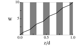
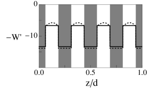
We examine a system in which the wavelength of the lamellar structure is because the effect of the ions is more easily seen in thin films. There are four layers of A, each of thickness , three layers of B, each of thickness and two layers of B next to the two plates, each of thickness . Were there no ions, the dimensionless potential would be as shown in Fig. 1. The presence of free ions does not noticeably affect the potential, even for values of the charge density corresponding to Presumably this is because the charge separation can never exceed and so is never macroscopic. The effect on the electric field , is small, but is discernible for a large charge density , and is shown in Fig. 2. The non-zero charge density, , can also be discerned, and is shown in Fig. 3. One sees that the variation of the charge density across each A lamella is essentially linear for small charge densities, being positive on one side of the lamellae and negative on the other. This is a result of the imposed charge neutrality of each lamella. For large charge densities, deviation from this linear behavior is expected.
III.1.2 Global Neutrality
Next consider the case in which the A layers are not constrained to be locally neutral; the system is only subject to the weaker constraint that the system be globally neutral. While the perpendicular orientation of lamellae is unaffected by the difference between these constraints, the parallel orientation is greatly affected. Each A lamella will now exhibit a non-zero charge density profile that is a function of the distance to the plates. Thus, there will be a dipole moment that scales with system size in the parallel orientation as well as in the perpendicular orientation. As a consequence, the latter has no obvious advantage over the former, and it is unclear whether there will be any reduction in the field needed to bring about a reorientation of lamellae.
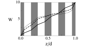
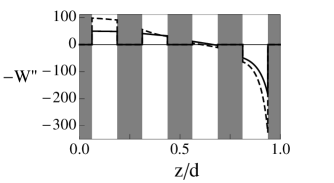
Results for the potential, electric field and charge density in the parallel orientation are shown in Figs. 4, 5, and 6, respectively, for various charge densities. For the small density of charges, , the potential is imperceptibly perturbed from the case of no ions, shown in Fig. 1, and the electric field hardly differs from the values and which would be obtained were there no ions. We also note that the electric field when is not symmetric about the midpoint of the sample, , because there is no symmetry on interchange of positive ions, which are fixed, and negative counterions, which are free to move.
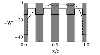
As the density of free ions is increased, the charges are free to migrate towards the bounding electrodes and to concentrate at the surfaces of the lamellae. The charge densities are much larger than in the locally neutral case. (Compare the scales of the charge density in Fig. 6 with those in the locally neutral case, Fig. 3). One notes from Fig. 6 that, for large charge densities, , the mobile negative charges are essentially depleted from the lamellae close to the negatively charged plate leaving behind a positive charge density with dimensionless value equal to . The charge separation is of order of the entire film thickness, . As a consequence, the electric field becomes increasingly screened, an effect most pronounced deep in the interior of the system and which spreads toward the two electrodes with increasing charge density. This is not difficult to understand. If one groups the layers of opposite charge in nesting pairs, with the outermost pair being at and , then the system resembles a set of nested capacitors, of alternating polarity, in series. As each capacitor contributes almost no field outside of its plates, the electric field can only be large near the two bounding surfaces of the entire system. In the limit of very large densities, it is clear that the charge is concentrated in the A lamella nearest the plates, and the field and associated potential drop is only significant in the B layers adjacent to the plates.
III.2 The Perpendicular Orientation
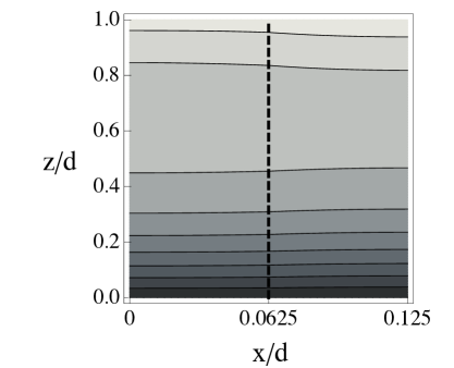
For the case in which the lamellae are perpendicular to the plates, we must solve the Poisson-Boltzmann equations in two dimensions. Because of periodicity and symmetry, it is sufficient to solve them only in an area of length in the direction and of length in the direction, from the middle of one A lamella to the middle of the adjoining B. Equipotential contours are shown in Fig. 7 for an applied potential and with a charge density . The boundary between A and B regions runs vertically through the center of the figure with the A region to the left, the B to the right. One sees immediately that there is little variation of the electric field from A to B regions. This is due to the fact that the lamellae are quite narrow compared to their height. But one also notices that the equipotentials are very different from the equally spaced ones which would characterize the potential in the absence of ions. Because the top, positive potential, plate attracts the negative mobile counterions, the electric field is screened effectively near it and the potential changes slowly; most of the change in potential occurs near the bottom plate.
As the density of free ions is increased, the lamellae act more and more like conductors, screening their interiors from the external electric field, just as in the parallel orientation. But in the perpendicular orientation, they provide a direct path between capacitor plates with the consequences that the external voltage source must place an increasing amount of charge on the plates in order to establish the requisite potential difference, and must expend ever more energy in order to do so.
III.3 The Transition between Orientations
With the solution of the Poisson-Boltzmann equations in hand for the two configurations, the corresponding free energies can be evaluated for any given external voltage, and in particular for voltages at which the perpendicular orientation of lamellae becomes of lower free energy than the parallel configuration. We calculate the free energies per unit area and for these two configurations and define
| (21) |
Further we note that in the perpendicular configuration because we have assumed that the A and B lamellae are of equal thickness. We assume that the surface fields cause the plates to prefer the less-polar polymer comprising the B lamellae, as in the experiments of Xu et al. xu04 , so that in the parallel configuration and . From a comparison of the total free energies of Eq. (12) for the two orientations, it follows that the perpendicular configuration is favored when
| (22) |
In Fig. 8 a plot of vs. the dimensionless applied voltage is presented for the case in which the A lamellae are locally neutral. The lamellar periodicity and film thickness are taken to be which corresponds to the system of Xu et al xu04 . Results for four different values of , the dimensionless density of the mobile ions, are shown.
The critical value of the external voltage needed to align the lamellae is simply determined by the value of at which a horizontal line drawn at the value intersects the curve . In particular, consider the experiments of Xu et al. xu07 for which A is PMMA, B is PS, and J m With an absolute temperature K, a periodicity nm and , the characteristic surface energy is J m-2 leading to a dimensionless surface energy difference of . A horizontal line at that value is shown in Fig. 8. We see that the dimensionless voltage needed to bring about alignment is reduced from the value without ions of about , corresponding to V, to about , or V, when the density of ions corresponds to . (For a film thickness nm, the unit of number density, m-3 so corresponds to m-3).
This reduction in critical voltage comes from the fact that the counterions do little to lower the electrostatic energy of the system when the lamellae are parallel to the substrate as well as locally neutral. In this case, there is no separation of charge on the order of the film thickness. But the ions do a great deal to lower the free energy when the lamellae are perpendicular to the plates so that there is a separation of charge on the order of the film thickness. Of course, this separation of charge decreases the entropy and is therefore opposed by thermal effects. In order to determine whether a reorientation will result from the two competing effects, one must carry out the calculation explicitly, as we have done, taking into account both the decrease of the free energy due to the reduction in electrostatic energy and the increase in free energy due to the decrease in counterion entropy. As the charge density increases without limit, the free energy of the perpendicular orientation at any non-zero voltage decreases without limit so that the curves of free energy difference approach the ordinate of Fig. 8, and the voltage needed to bring about reorientation approaches zero.
We next consider the less restrictive case when the system is globally neutral. The free energy difference between perpendicular and parallel orientations is shown in Fig. 9. Again there is a reduction in the voltage needed to reorient the lamellae, from (, or no ions) to for . This is a much smaller reduction than in the locally neutral case for which the reorienting potential was driven down to for . The reason that there is any reduction in the reorienting voltage in the globally neutral case is subtle for there is a macroscopic separation of charge in both orientations. However, while the charge in the perpendicular alignment can be separated by a distance , in the parallel alignment it can only be separated by a smaller distance when the B layer is next to the plates. Hence, the ions lower the free energy of the perpendicular configuration more than that of the parallel one with a consequent reduction in critical voltage. Because the difference between charge separations of and is relatively larger the smaller the value of , we expect that the relative reduction of the potential needed to reorient the film is greater for thinner films. We have verified this conclusion by calculating results for films in which was reduced to 4. Whereas in the film there is a reduction in the reorientation potential of about % when the dimensionless surface field is equal to 100 and the density of ions is , in the thinner film the reduction for the same surface field and ion density is about %.
Were the A material preferentially adsorbed to the plates, there would be a macroscopic separation of charge of order in both orientations. In fact, the polarization would be somewhat larger in the parallel orientation in which the free charges could coat the plates entirely as contrasted with the perpendicular configuration in which they could coat only half the area of the plates. Thus we would expect that the addition of ions actually enhances the parallel orientation with respect to the perpendicular and would cause the critical voltage to increase rather than decrease. We have verified that this is indeed the case, although the increase in critical voltage is not large. We also expect the effective surface tension of the A block with the substrate to be reduced by an amount . This expression is identical to the reduction of the liquid-solid interfacial tension of polar liquids in external potentials (electrowetting) mugele2007 .
IV Conclusions
We have considered a system composed of lamellae with two different dielectric constants and in which one kind, the A lamellae, contain mobile negative ions in a smeared continuum background of positive ones. We calculated the effect of these ions on the free energy when the lamellae are oriented in the direction of the applied field and compared it to that when the lamellae are oriented parallel to the two external electrodes, which is the orientation favored by surface interactions. We have assumed that the system is in thermal equilibrium so that the comparison of these free energies determines the magnitude of the applied voltage necessary to bring about the reorientation of the lamellae.
The effect of the ions can be quite significant, but we have shown that it depends on several factors. The ions have their largest effect if the system is locally neutral, i.e. they neutralize the background charge of each of the A lamellae of the film. In that case, a macroscopic separation of charge, with its concomitant lowering of energy, can only be brought about if the lamellae undergo the desired reorientation. We find that for the surface interactions commonly encountered, the voltage needed to bring about the reorientation could be reduced by more than half. These results are in fine qualitative agreement with the experiments of Kohn et al. kohn09 whose system was one of local neutrality. By applying alternating electric fields at various frequencies, they could explicity determine the effect of the free ions as contrasted with those originating from the different dielectric constants. They indeed found that at lower frequencies at which the effects of the free ions become important, the orienting effect of the electric field was enhanced kohn09 ; tsori2003 .
For systems in which the mobile ions can move from one A lamella to another so that it is only restricted to be globally neutral, the effect of the ions is predicted to be smaller than in the locally neutral case, and to depend on other factors as well. In particular, if the system is globally neutral, we predict that the effect is greater if the surface interactions prefer the B (no ions) lamellae, for then the separation of charge in the perpendicular orientation is larger than that in the parallel one. The relative reduction in the reorienting potential should be the greater the thinner the film. If the surface interactions prefer the A layers, then the presence of ions can actually increase the voltage needed to bring about the reorientation.
Insight into the question of whether the lamellae of a particular system are locally or globally neutral can be obtained by altering the plates so that they prefer A in one experiment and B in another. A locally neutral system will be relatively unaffected by such a change, while a globally neutral one would be significantly changed. An alternative is to solubilize a known amount of ions in the pure polymers. Integration of the current that passes through the polymer at a given external potential allows one to infer the fraction of immobile ions and the solubilization energy.
We have noted that separation of charge which occurs on the scale of the film thickness decreases the entropy making reorientation more difficult. Hence a reduction of temperature certainly makes it easier to bring about the reorientation. In our calculation, this is reflected in the definition of the dimensionless measure , Eq. (14), which shows that a decrease in temperature is equivalent to an increase in ionic charge density.
At constant temperature, all properties of the system depend upon the ratio of the ion density to the applied potential, , as seen, from Eq. (17). Hence for a system with a given ion density at a fixed temperature, any “effective” dielectric constant must depend upon the applied voltage itself, and is therefore not a particularly useful concept.
Finally the effects of the ions in our system cannot be attributed to a change in the strength of the interaction between components, so whatever role such an effect may play in diblock copolymer systems wang08 , it is supplementary to the equilibrium effects considered here.
In sum, we have calculated the change in the aligning potential that can be expected upon the introduction of ions into a patterned system of different dielectric material tsori03 such as block copolymer, and have highlighted some of the issues to be addressed in order to exploit such systems for further applications.
Acknowledgments We gratefully acknowledge useful correspondence with A. Böker, T. Russell, S. Stepanow, T. Thurn-Albrecht and J.-Y. Wang. This work was supported by the U.S.-Israel Binational Science Foundation under Grant No. 2006055 (DA, MS), by the National Science Foundation under Grant No. DMR-0803956 (MS), the Israel Science Foundation under Grants No. 284/05 (YT) and No. 231/08 (DA), and by the German Israeli Foundation under Grant No. 2144-1636.10/2006 (YT).
Appendix I: Derivation of the Electrostatic Energy
To obtain the partition function of the system, one must first obtain the energy of a given configuration of charges. The electric energy is specified by the number density of the mobile negative charges
| (I.1) |
where is the position vector of the ’th charge. The energy is obtained in the standard way and leads to the usual result for a linear dielectric
| (I.2) |
where the potential, , is a functional of the number density via the Poisson equation
| (I.3) |
This energy, however, does not include the work that the external electric power source, which is part of the system, must do in order to keep constant the potential difference between the two electrodes landau84 . We include this contribution to the energy and denote the result for the total energy of the system Using the fact that one plate is at potential zero, and the other at potential , the decrease in total energy can be written
| (I.4) | |||||
| (I.5) | |||||
| (I.6) | |||||
| (I.7) | |||||
| (I.8) |
In Eq. (I.4) above, the charge density of the upper plate is denoted with the position vector in the plane of the plate. The Maxwell equation has been used to express this charge density in terms of the component of the displacement field just outside the plate, , which appears in Eq. (I.5), and again to relate the divergence of the displacement field in the bulk dielectric, Eq. (I.7), to the free charge there, Eq. (I.8). The second integral in that equation is over the regions of A lamellae which contain the charges. Combining the expressions of Eqs. (I.2) and (I.8) we obtain for the energy of the system the expression
| (I.9) |
which, like the potential is a functional of the charge density The partition function in the canonical ensemble is
| (I.10) |
where is the de Broglie wavelength of the negative charges.
There are many methods to obtain from the exact partition function the mean-field approximation to the free energy, such as that pioneered by Edwards edwards65 and used commonly sinceborukhov00 ; fredrickson06 ; negele88 . They all lead to the result
| (I.12) |
where , in contrast to of Eq. (I.1), is an ensemble-average density
| (I.13) |
and is the source of the potential via the Poisson equation
| (I.14) |
The mean-field free energy, Eq. (Appendix I: Derivation of the Electrostatic Energy), is seen to be simply the total electrostatic energy, Eq. (I.9), but as a function of this average charge density, supplemented by the contribution to the entropy of the mobile counterions.
Appendix II: Numerical Solutions
The rescaled electrostatic free energy defined in Eq. (11) can be written in terms of the rescaled potential by using the relation to eliminate the explicit dependence on in Eq. (9). The result, after changing to rescaled variables and neglecting a constant which contributes equally to the parallel and perpendicular configurations, is
| (II.1) | |||||
This expression is valid for both the globally neutral parallel configuration and the perpendicular configuration. In the case of locally neutral parallel lamellae, each lamella labeled by has its own constant and the rescaled free energy is
| (II.2) | |||||
where is the volume taken up by the th lamella within the integration region . These rescaled free energies can be calculated once the rescaled potential and the constant (or constants in the case of locally neutral lamellae) have been determined by numerically solving discretized versions of the equations
| in B regions | (II.3) |
subject to appropriate boundary conditions. In the case of parallel lamellae where is a function of only, the following boundary conditions hold in both the locally and globally neutral cases:
| (II.4) | |||||
| (II.5) | |||||
| (II.6) | |||||
| (II.7) |
where the AB interfaces are indexed by and and are the relative dielectric constants on the two sides of the interface at . In the case of globally neutral lamellae, the unknown is determined by the boundary condition
| (II.8) |
In the case of locally neutral lamellae, each unknown is determined by a boundary condition describing the neutrality of the th A-lamella:
| (II.9) |
where is the number of A-lamellae and and are the scaled positions of the edges of the th such lamella. For the perpendicular configuration, the boundary conditions are
| (II.10) | |||
| (II.11) | |||
| (II.12) | |||
| (II.13) | |||
| (II.14) | |||
| (II.15) | |||
| (II.16) |
where is in the middle of an A lamella, so that is the location of the AB interface. Eqs. (II.13) and (II.14) enforce the symmetry of the system with respect to reflection about the center of each A or B lamella, respectively. Eq. (II.16) determines the value of by enforcing the neutrality of the system.
References
- (1) M. Park, C. Harrison, P. M. Chaikin, R. A. Register and D. H. Adamson, Science, 276, 1997, 1401.
- (2) S. Walheim, E. Schaffer, J. Mlynek and U. Steiner, Science, 283, 1999, 520.
- (3) T. L. Morkved, M. Lu, A. M. Urbas, E. E. Ehrichs, H. M. Jaeger , P. Mansky and T. P. Russell, Science, 273, 1996, 931.
- (4) T. Thurn-Albrecht, J. Schotter, G. A. Kastle, N. Emley, T. Shibauchi , L. Krusin-Elbaum, K. Guarini, C. T. Black, M. T. Tuominen and T. P. Russell, Science, 290, 2000, 2126.
- (5) W. A. Lopes and H.M. Jaeger, Nature, 414, 2001 , 735.
- (6) C. Park, J. Yoon and E.L. Thomas, Polymer, 44, 2003, 6725.
- (7) K. Amundson , E. Helfand , X. Quan and S. D. Smith, Macromolecules, 26, 1993, 2698.
- (8) K. Amundson, E. Helfand, X. Quan, S. D. Hudson and S. D. Smith, Macromolecules, 27, 1994, 6659.
- (9) G. G. Pereira and D. R. M. Williams, Macromolecules, 32, 1999, 8115.
- (10) A. Boker, A. Knoll, H. Elbs, V. Albetz, A.H.E. Muller and G. Krausch, Macromolecules, 35, 2002, 1319.
- (11) Y. Tsori and D. Andelman, Macromolecules, 35, 2002, 5161.
- (12) B. Ashok, M. Muthukumar and T.P. Russell, J. Chem. Phys., 115, 2001, 1559.
- (13) Y. Tsori, F. Tournilhac, D. Andelman and L. Leibler, Phys. Rev. Lett., 90, 2003, 145504.
- (14) T. Xu, J.T. Goldbach, J. Leiston-Belanger and T. P. Russell, Colloid Polym. Sci, 282, 2004, 927.
- (15) J.-Y. Wang, T. Xu, J. M. Leiston-Belanger, S. Gupta and T.P. Russell, Phys. Rev. Lett., 96, 2006, 128301.
- (16) J.-Y. Wang, W. Chen, C. Roy, J. D. Sievert and T.P. Russell, Macromolecules, 41, 2008, 963.
- (17) A.-V. G. Ruzette, P. P. Soo, D. R. Sadoway and A. M. Mayes, J. Electrochem. Soc., 148, 2001, A537.
- (18) T. H. Epps, T. S. Bailey, H. D. Pham and F. S. Bates, Chem. Mater., 14, 2002, 1706.
- (19) S.F. Edwards, Proc. Phys. Soc., 85, 1965, 613.
- (20) I. Borukhov, D. Andelman and H. Orland, Electrochimica Acta, 46, 2000, 221.
- (21) G. Fredrickson, The Equilibrium Theory of Inhomogeneous Polymers, Oxford University, Oxford, 2006.
- (22) J.W. Negele and H. Orland, Quantum Many-Particle Systems, Addison Wesley, Redwood City, 1988.
- (23) P. Kohn, K. Schröter and T. Thurn-Albrecht, Phys. Rev. Lett., 102, 2009, 216101.
- (24) T. Xu, J. Wang, and T.P. Russell, in Nanostructured Soft Matter, ed. A.V. Zvelindovsky (Springer, Berlin, 2007), pp. 171-198.
- (25) F. Mugele and J. Buehrle, J. Phys.: Condens. Matter, 19, 2007, 375112.
- (26) L. D. Landau, E. M. Lifshitz and L. P. Pitaevskii, Electrodynamics of Continuous Media, Pergamon Press, Oxford, 1984.
- (27) Y. Tsori, F. Tournilhac, and L. Leibler, Macromolecules, 36, 2003, 5873.
Figure Captions
-
Figure 1. Parallel case, no ions (). The dimensionless applied potential is and The sample thickness and wavelength are related by The dimensionless potential, is plotted vs. the dimensionless coordinate . A-type regions are shown in white, B regions in gray.
-
Figure 2. Parallel case, local neutrality. The dimensionless applied potential is and The sample thickness and wavelength are related by The dimensionless electric field, , is plotted vs. the dimensionless coordinate . A-type regions are shown in white, B regions in gray. The case for no ions, is shown with solid lines, while is shown with a dotted line.
-
Figure 3. Parallel case, local neutrality. The dimensionless total charge density, , is plotted for , The sample thickness and wavelength are related by Solid line, ; dashed line, .
-
Figure 4. Parallel case, global neutrality. The dimensionless potential for , , and with varied. Solid line, ; dashed line, ; dotted line, . The sample thickness and wavelength are related by .
-
Figure 5. Parallel case, global neutrality. The dimensionless electric field, is plotted for , , and with varied. Solid line, ; dashed line, . The sample thickness and wavelength are related by
-
Figure 6. Parallel case, global neutrality. The dimensionless charge density, , is plotted for , , and with varied. Solid line, ; dotted line, . The sample thickness and wavelength are related by .
-
Figure 7. Perpendicular case. Contours of constant dimensionless potential, , at intervals of 1.0 are plotted in the plane for and . As , we need only plot from 0.0 to The interface between A and B lamellae is at with the A region to the left and B to the right of it. Areas between equipotentials are filled with different shades of gray for clarity.
-
Figure 8. The difference between the dimensionless electrostatic free energies per unit area (without surface fields) of the perpendicular orientation and the locally neutral parallel orientation is shown as a function of dimensionless applied voltage for four values of ion number density; (solid line), (dashed line), (dotted line), and (dotted-dashed line). The sample thickness and wavelength are related by The horizontal line is at the value (see text).
-
Figure 9. The difference between the dimensionless electrostatic free energies per unit area (without surface fields) of the perpendicular orientation and the globally neutral parallel orientation is shown as a function of dimensionless applied voltage for four values of ion number density; , (solid line) (dashed line), (dotted line), and (dotted-dashed line). The sample thickness and wavelength are related by The horizontal line is at the value (see text).