Spin-polarized current
in ferromagnetic rod-to-film structure
Abstract
Properties are discussed of a ferromagnetic junction of the type “rod contacting with film”. Very high current density of the order of A/cm2 may be achieved in the contact region. We show it can lead to inversion of population of the spin energy subbands. Spin injection depends strongly on the direction of the current (forward or backward). We prepared experimentally a rod-to-film structure and investigated high density current flowing through it. Current dependent radiation has been observed by means of a THz receiver. In particular, the radiation becomes different for forward and backward currents. It shows the radiation includes not only heating but also non-thermal (spin-injection) effects.
1 Introduction
Current-induced spin injection is one of the fundamental spintronic effects. As a very interesting application of the effect, a possibility has been discussed of generating THz radiation by creating inverse population of the spin subbands in a ferromagnetic layer under intense spin injection [1, 2]. By estimates, current density of the order of A/cm2 is needed to realize the inverse population regime in one of the layers of a magnetic junction [2].
A scheme was proposed for reaching high current density in a rod– thin film system [3]. If the film thickness is small compared to the rod radius , then the current density in the film near the rod is times the current density in the film that allows to reach high current density and spin injection intensity in the film. In this work, we consider briefly the injection properties of such a structure and present preliminary experimental results.
2 Properties of the rod-to-film structure
We consider a layered structure including two circular in plane metallic ferromagnetic layers: layer 1 having small radius m and large enough thickness and layer 2 having large radius and very small thickness nm, being . Therefore we consider layers with very different geometric parameters, for example, a rod contacting with a thin film.
We calculate the electron spin distribution in the structure when electrons flow in direction. Detail of the calculation is in Refs. [3, 4]. Spin polarization in layer 2 satisfies the continuity equation
| (1) |
where are the electron densities in low and high energy spin subbands, respectively, is the total electron density, which is constant in the layer due to the charge neutrality condition, is the equilibrium spin polarization, is the current density, is a characteristic diffusion current density, is the electron charge, is the spin diffusion length, is the spin diffusion constant, is the spin relaxation time. Equation (1) was solved analytically using cylindrical coordinates with the conditions of charge and spin currents continuity at the boundaries of the layers. Very high current density of the order of A/cm2 appears near the boundary between layers 1 and 2, which exceeds by times the current in the layer 1. The inversion of spin population may be created in layer 2 due to the spin injection by current from layer 1.

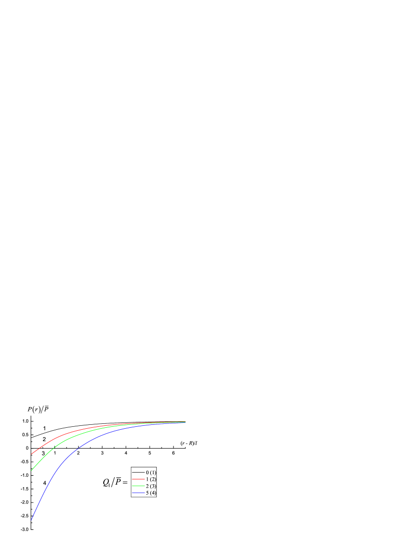
The resulting spin polarization tends to the equilibrium value in the film, when we are moving far from the rod edge. Calculated spatial distribution of the polarization is shown in Fig. 1 at several values of ratio, where
| (2) |
is the spin polarization of conductivity in layer 1. We see that the inversion of spin population () may appear at large enough values of that ratio.
The calculated dependence of the relative spin polarization on the relative current density near the boundary between layers 1 and 2 is shown in Fig. 2. Curves 1–4 correspond to rising spin injection by current. We see the inversion of spin population may be achieved. Such a possibility was discussed previously in a number of works [2, 5, 6].
The highest (in magnitude) negative value of the nonequilibrium spin polarization achieved at the boundary of the rod was obtained in the form (see Eq. (20) in [4])
| (3) |
where are the unit magnetization vectors in layers 1 and 2, respectively, is the modified Bessel function of the second kind with index
| (4) |
The most significant consequence of the formulae (3) and (4) is the fact that the nonequilibrium polarization depends on the current both directly and via the index , being nonsymmetrical with respect to changing the current sign, . Therefore the spin-injection contributes to , and the contribution is different for forward and backward directions of the current.
3 Experimental structure
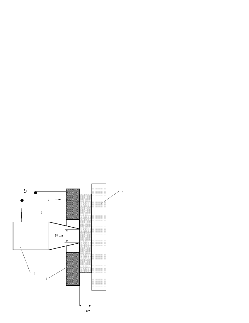
We designed a structure (Fig. 3) consisted of a metallic ferromagnetic rod 3 and film 1 contacted each other. This structure will be named further as a “rod-to-film” one. It is simply a kind of a magnetic junction which has specific properties. The current-carrying rod was taken of hardened steel having approximately circular cylindrical form and minimal radius m. In contrast to the rod, the film part of the structure was taken magnetically soft, for example, a film of Permalloy. Moreover, the thickness of the film was small enough, namely, nm. The film was deposited onto a dielectric substrate 2. The other current-carrying lead was a copper plate 4 which the magnetic film was pressed to by means a fluoroplastic plate 5. The rod was contacting with the film through a hole in the copper plate.
As mentioned above, such a construction allows to obtain high current density (more than A/cm2).
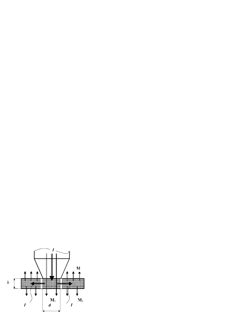
Based on some model experiments, a preliminary conclusion was made about the magnetization distribution in the Permalloy film (Fig. 4). The rod has its own magnetization along the axis that leads to spin polarization of the current. Due to low coercivity of the film, its magnetization reverses by the rod magnetic field. The part of the film near the surface contacting with the rod has magnetization with direction opposite to , while the part near the other surface has magnetization along . Therefore, a situation may be obtained where the spin-polarized electrons entering to the film from the rod find themselves in a region with antiparallel magnetization, i. e., in the higher spin subband. This can allow creating inverse spin population in the film, so that the structure can work as a spin-injection emitter.

4 Measurements and results
We measured radiation from the structure with a stand shown in Fig. 5. The signal from emitter 1 passed from the rod–film contact through the dielectric substrate and low-frequency filter 2 was detected with Golay cell 3. The low-frequency filter in form of a metal grid with meshes of m2 was used to cut off long-wavelength signals, because the Golay cell can detect signals in a wide wavelength range from 10 m to 8 mm. A pulse generator 4, used as a current source, allowed pulsed current flowing through the system with pulse amplitude up to 0.8 A and various pulse durations and repeating frequencies, so that the pulse period-to-pulse duration ratio (PPPDR) was varied from 2 to 20. As a result, current density of A/cm2 could be created in the operating range without breaking the system. The current pulse parameters were measured by a digital oscillograph 5, while the time depending radiation intensity was registered by a digital recorder 6.
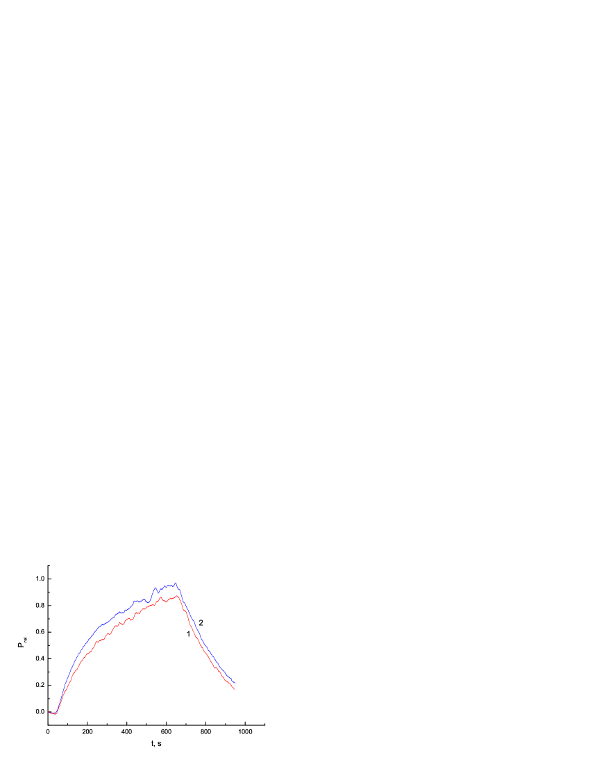
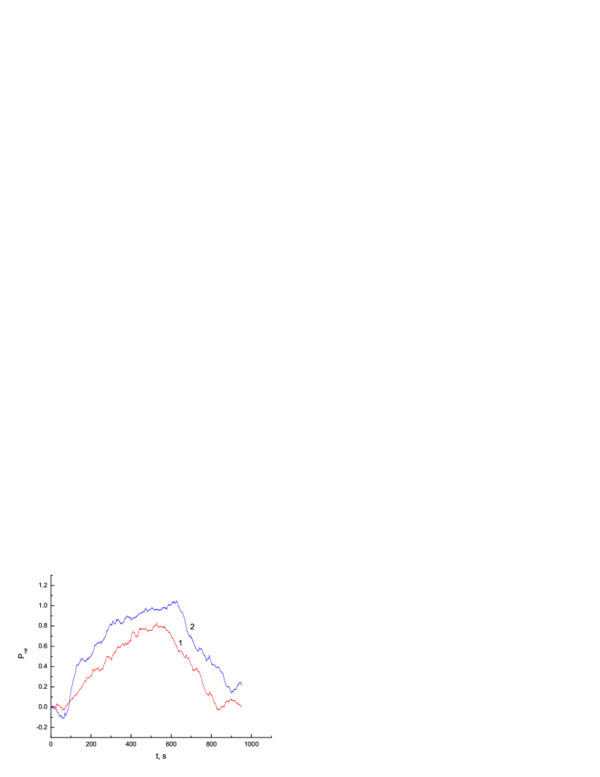
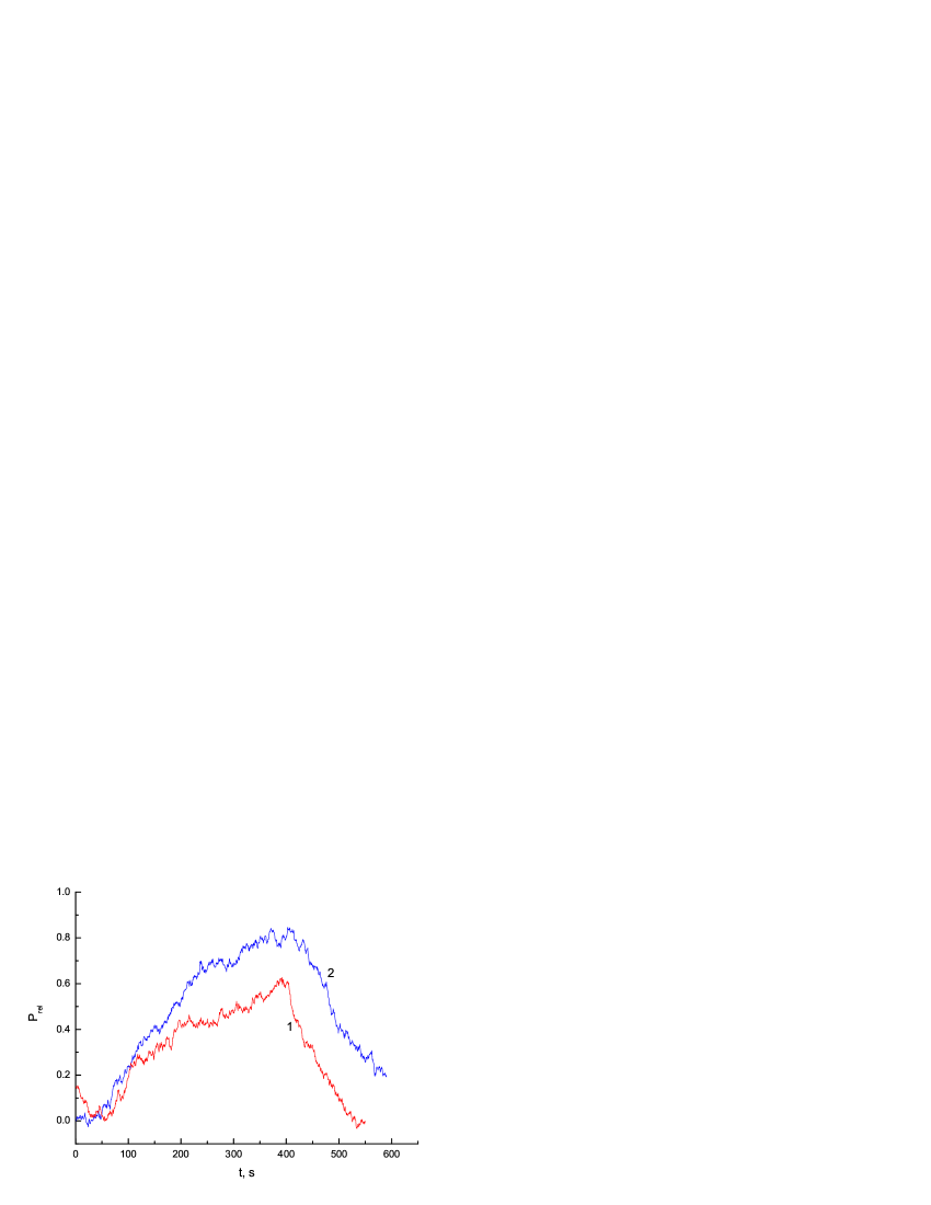
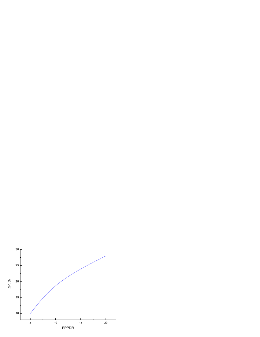
Measurements were made of the radiation intensity time dependence under forward and backward current flowing. Various PPPDR values were used. The results are shown in Figs. 6–8. A summary curve in Fig. 9 shows maximal difference in the radiation intensities between forward and backward currents as a function of PPPDR value. It is seen that the measured intensity depends on the current direction. The difference increases with increasing PPPDR, i. e. with decreasing heating effect. The difference disappeared when the magnetic (steel) rod was changed with nonmagnetic (copper) one. This allows to suppose that we have to deal with a non-thermal effect of the current here. Indeed, if the observed radiation is a sum of the thermal and non-thermal ones, then the thermal radiation intensity must decrease with PPPDR increasing, while the non-thermal one must remain fixed. The total intensity decreases, but the ratio of the non-thermal radiation intensity to the thermal one must increase, as we observe.
The results obtained are unlikely may be related with thermoelectric and thermomagnetic phenomena such as the Peltier and Ettingshausen effects. For metals, these effects may be estimate as a fraction of a degree, while we have heating up to 10–15 degrees.
5 Discussion
Two interesting facts have been observed in our measurements, namely, presence of a non-thermal contribution to THz radiation from the system in study and difference between the radiation intensities under forward and backward current direction. It was shown earlier [7] that the current-induced spin injection from a ferromagnetic layer to another one depended substantially on the current polarity. Therefore, the facts mentioned may be due to the radiation created by the nonequilibrium spins near the rod–film boundary. However, more detail measurements are needed to validate this assumption. We plan to continue this work.
Acknowledgment
The authors are grateful to Prof. G.M. Mikhailov, Dr. V.N. Kornienko and Dr. G.A. Ovsyannikov for valuable discussions.
The work was supported by the Russian Foundation for Basic Research, Grants Nos. 08-07-00290 and 10-02-00039.
References
- [1] A. M. Kadigrobov, Z. Ivanov, T. Claeson, R. I. Shekhter, M. Jonson, Europhys. Lett. 67, 948 (2004).
- [2] Yu. V. Gulyaev, P. E. Zilberman, A. I. Krikunov, A. I. Panas, E. M. Epshtein, JETP Lett. 85, 160 (2007).
- [3] S. G. Chigarev, A. I. Krikunov, P. E. Zilberman, A. I. Panas, E. M. Epshtein, J. Commun. Technol. Electron. 54, 708 (2009).
- [4] Yu. V. Gulyaev, P. E. Zilberman, A. I. Panas, S. G. Chigarev, E. M. Epshtein, J. Commun. Technol. Electron. 55, No. 6 (2010).
- [5] V. V. Osipov, N. A. Viglin, J. Commun. Technol. Electron. 48, 548 (2003).
- [6] N. A. Viglin, V. V. Ustinov, V. V. Osipov, JETP Lett. 86, 193 (2007).
- [7] Yu. V. Gulyaev, P. E. Zilberman, A. I. Panas, E. M. Epshtein, J. Exp. Theor. Phys. 107, 1027 (2008).