Phase separation versus supersolid behavior in frustrated antiferromagnets
Abstract
We investigate the competition between spin-supersolidity and phase separation in a frustrated spin-half model of weakly coupled dimers. We start by considering systems of hard-core bosons on the square lattice, onto which the low-energy physics of the herein investigated spin model can be mapped, and devise a criterion for gauging the interplay between supersolid order and domain wall formation based on strong coupling arguments. Effective bosonic models for the spin model are derived via the contractor renormalization (CORE) algorithm and we propose to combine a self-consistent cluster mean-field solution with our criterion for the occurrence of phase separation to derive the phase diagram as a function of frustration and magnetic field. In the limit of strong frustration, the model is shown to be unstable toward phase separation, in contradiction with recently published results. However, a region of stable supersolidity is identified for intermediate frustration, in a parameter range not investigated so far and of possible experimental relevance.
pacs:
75.10.Jm, 03.75.Nt, 05.30.JpI Introduction
Dimer-based antiferromagnets (DAFs) under a magnetic field are promising candidates for displaying new phases of bosonic matter.Giamarchi et al. (2008) Magnetic excitations in such systems, termed triplons, are well described by lattice models of interacting bosons, whose density can be finely tuned by varying the magnitude of the applied field.Mila (1998); Totsuka (1998) Experimentally, field-induced Bose-Einstein condensation (BEC) of triplons has been observed in a number of DAFs (see the review Ref. Giamarchi et al., 2008) and, remarkably, exotic quantum criticality has been detected in the spin-dimer compound . Sebastian et al. (2006); Rüegg et al. (2007); Krämer et al. (2007); Laflorencie and Mila (2009) The presence of magnetic frustration further adds to the rich phenomenology of these systems by enhancing repulsive interactions between triplons, something that may eventually stabilize incompressible phases that break the lattice’s translational symmetry.Mila (1998); Takigawa and Mila (2010) Such crystalline phases are for instance realized in the Shastry-Sutherland material ,Kageyama et al. (1999); Kodama et al. (2002) where they are signaled by a series of magnetization plateaux at unconventional fillings stabilized by complex triplon interactions. Dorier et al. (2008)
The occurrence of both BEC and solid phases in the phase diagram of DAFs under magnetic field suggests that the magnetic equivalent of the phase simultaneously displaying diagonal and off-diagonal order known as supersolid (SS)Andreev and Lifshitz (1969); Kim and Chan (2004a); Balibar (2010) may be realized in these systems. Indeed, insofar as more exotic possibilities are excluded,Senthil et al. (2004) according to the Ginzburg-Landau-Wilson paradigm a continuous transition between phases breaking different symmetries (as it is the case with BEC and crystalline phases) is precluded and we are therefore left with two possibilities: (i) a first-order transition or (ii) the appearance of an intermediate phase, where both order parameters coexist, termed spin-supersolid (spin-SS) in the present context. The latter possibility has been first investigated by Momoi and Totsuka for the Shastry-Sutherland model in the vicinity of half- and third-filling plateaux,Momoi and Totsuka (2000) based on a mean-field analysis of an effective bosonic model derived up to third-order in the inter-dimer coupling. More recently,Dorier et al. (2008) state-of-the-art techniques have been employed in deriving effective models that improve upon the third-order effective Hamiltonian of Ref. Momoi and Totsuka, 2000. Unfortunately, the reliability of these methods is still limited to inter-dimer couplings equal to, at most, one-half of the intra-dimer coupling, and in that parameter range the different plateaux seem to be separated by first-order transitions without any convincing evidence of spin-SS phases.Dorier et al. (2008)
The situation is much clearer for the DAF investigated in Ref. Ng and Lee, 2006 where repulsion among triplons are enhanced due to the strong Ising-like character of the inter-dimer exchange [see Eq. (1) in Ref. Picon et al., 2008], making room for checkerboard solid (CBS) and spin-SS phases to emerge. The absence of frustration allows for quantum Monte Carlo (QMC) simulations to be performed and, in this way, the occurrence of a spin-SS phase for the model studied in Ref. Ng and Lee, 2006 has been firmly established. However, such a strongly anisotropic Hamiltonian is unrealistic for Mott insulating materials and further investigations of models where the kinetic energy is instead reduced by frustration of isotropic couplingsSengupta and Batista (2007); Chen et al. (2010) are clearly called for if connection to experiments is ever to be made.
In this context, the recent report of a spin-SS phase in a spin-half frustrated DAF by Chen et al.,Chen et al. (2010) who have relied on a novel tensor-product algorithm, is an important result. However, in view of the first-order transitions observed in the related case of the Shastry-Sutherland model, a systematic investigation of the possibility of phase separation (PS) is still required.
In this paper, we investigate the interplay between SS order and PS in the frustrated DAF analyzed in Ref. Chen et al., 2010. We begin by estimating the energetic gains behind PS and supersolidity for hard-core bosons on the square lattice by relying on strong coupling arguments, and introduce an indicator of the instability toward PS. We then proceed to the analysis of effective bosonic models obtained from the application of the Contractor Renormalization (CORE) algorithmMorningstar and Weinstein (1994) to the DAF investigated in Ref. Chen et al., 2010. The so-obtained effective Hamiltonians are studied by performing self-consistent cluster mean-field theory (SCMFT) calculations and tendency toward PS is gauged through means of the aforementioned indicator.
II Phase Separation versus Supersolidity for Lattice Bosons
In this section, we analyze the interplay between PS and supersolidity in models of hard-core bosons on the square lattice, onto which the low-energy physics of the spin model considered in the remainder of this paper can be mapped.
II.1 Instability to Domain Wall Formation
We start by considering the simplest model of hard-core bosons on the square lattice, the so-called model:
| (1) |
is the occupation number operator for holeshol at site (a hard-core constraint is imposed), whose density is controlled by the chemical potential . Here, only nearest-neighbor (NN) hopping () and interaction () terms are considered but, as will be discussed later, the effective model derived for the spin model Eq. (3) further comprises longer-ranged and/or multi-body couplings.
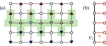
The model Eq. (1) had been for many years conjectured to support SS phases (see Refs. Scalettar et al., 1995; Batrouni and Scalettar, 2000 and references therein), but a more systematic numerical analysisBatrouni and Scalettar (2000) later disproved earlier evidences in favor of this scenario and showed that, instead, PS prevents the occurrence of supersolidity. An intuitive explanation for such behavior was put forward in Ref. Sengupta et al., 2005 by relying on strong coupling arguments. Following this analysis,Sengupta et al. (2005) holes [or also particles in the case of Eq. (1);hol however, the effective models to be analyzed later lack particle-hole symmetry] doped into the CBS ground-state of Eq. (1) for at half-filling would delocalize with an effective hopping amplitude proportional to and eventually condense, giving origin to SS order. However, this last conclusion is flawed in that it ignores the possibility of PS. Indeed, in the strongly interacting regime domain wall [DW, depicted as the shaded region in Fig. 1(a)] formation is energetically favored for the model Eq. (1): the energetic gain per doped hole (we denote the number of doped holes by ) is linear in under these circumstances, with .Sengupta et al. (2005)
Since one of our primary goals in the present work is to investigate the interplay between PS and supersolidity, so to be able to decide which among the two possibilities take place for the spin model herein analyzed [Eq. (3)], we would like to obtain a more accurate estimate for ; in other words, we would like to pinpoint the actual values assumed by . In achieving this goal we completely ignore fluctuations in CBS-ordered regions away from DWs, a supposedly good approximation for , and consider a simplified -like model at half-filling (quarter-filling for doped holes) defined on the “comb” geometry depicted in Fig. 1(b). In such a simplified model hopping processes with amplitude only take place in between NN sites linked by the comb’s “teeth” and interaction is only active for holes sitting on NN sites along the “backbone” [see Fig. 1(b)].
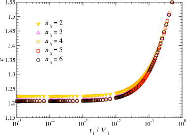
In Fig. 2 we plot results for , as a function of , obtained from exact diagonalizations (EDs) of the just discussed simplified model on the comb geometry depicted in Fig. 1(b), for clusters comprising up to sites (thus, up to doped holes). We first notice that in the limit of large . On the other hand, since fluctuations away from the DW are ignored in our analysis, we expect our ED results to underestimate for small values of . Nonetheless, we keep this limitation in mind and throughout the remainder of this paper rely on ED results in estimating the DW energy even in the weakly interacting regime . In doing so, we take advantage of the very small finite size effects in the data shown in Fig. 2 and obtain from EDs on finite clusters.
II.2 Leapfrog Mechanism for Supersolidity
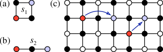
In a previous work,Picon et al. (2008) we have shown that the instability toward PS is suppressed in models of hard-core bosons on the square lattice that include, in addition to the terms comprised in the model [Eq. (1)], the correlated hopping processes with amplitudes and depicted in Fig. 3. Indeed, such correlated hopping terms have been shownSchmidt et al. (2008); Picon et al. (2008) to favor supersolidity by allowing doped holes to delocalize on top of a CBS by “leapfrogging” on the other sub-lattice. We wish now to devise a criterion for determining how large should the amplitudes and be so to inhibit DW formation and thus stabilize a SS. In doing so, we once more rely on strong coupling arguments, and estimate the energetic gain associated to the leapfrog processes represented in Fig. 3 as
| (2) |
That is, is simply the ground-state energy of a single hole doped into a “frozen” CBS, an approximation expected to hold for , hopping via the processes with amplitude and [Fig. 3(a-b)]. As it happens for our estimate obtained in Sec. II.1, we expect as given by Eq. (2) to underestimate the actual energetic gain associated to the leapfrog processes.
We combine the just presented analysis and the one discussed in Sec. II.1 concerning DW formation and introduce an indicator for analyzing the interplay between supersolidity and PS: the difference between [Eq. (2)] and (obtained from EDs by using as input; see Secs. II.1), our estimates for the energetic gains respectively associated to each of these possibilities. Since both estimates are obtained from strong coupling analysis, the indicator can only be expected to be accurate in the limit of . However, we keep this limitation in mind and in the analysis to be performed in Sec. III, we rely on as an indicator even for couplings .
III Frustrated Spin Model
III.1 Model and Effective Hamiltonian
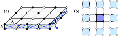
In most of the lattice models that have, so far, been shown to display SS properties the effective repulsion (necessary to destabilize the uniform superfluid and induce a SS state) stems from the presence of nearest-neighbor repulsive terms in XXZ Hamiltonians.Wessel and Troyer (2005); Ng and Lee (2006); Picon et al. (2008) While these anisotropic models are interesting from a theoretical perspective, their strong anisotropic character renders them unrealistic for antiferromagnetic Mott insulators. More promising in this sense is the frustrated spin-half Hamiltonian analyzed in Ref. Chen et al., 2010, defined on a bilayer geometry [Fig. 4(a)]
| (3) |
denotes NN sites in each square layer of the frustrated bilayer depicted in Fig. 4(a). couples spins in different layers to build the basic dimers of the model (we set ). The applied magnetic field acts as a chemical potential, promoting spin-dimers from a singlet (hole) to a triplet (triplon) state. Effective interactions appear as the result of in-layer and frustrating antiferromagnetic couplings. We remark that the lattice depicted in Fig. 4(a) remains invariant if every other spin-dimer is rotated by and thus Eq. (3) is invariant under the transformation , with the consequence that the phase diagram is symmetric about the line .
In studying the model of Eq. (3), we adopt an approach similar to the one employed in our previous work Ref. Picon et al., 2008, where a related unfrustrated model was investigated and to which the reader is referred for details,hol and derive an effective bosonic model by relying on the CORE algorithm.Morningstar and Weinstein (1994) We consider spin-dimers connected by as elementary blocks and select the singlet and the triplet as the block states in the CORE expansion: for all parameters in Eq. (3) considered in the present work, , this choice is justified by the large reduced density-matrix weights associated to such block states and by the rapid convergence of effective couplings for increasing range in the expansion.Abendschein and Capponi (2007) Effective couplings are derived by diagonalizing clusters of coupled dimers and by projecting a matching number of low-lying cluster eigenstates onto the basis formed by tensor products of the retained block states, and .rem The effective bosonic Hamiltonian thus obtained is essentially identical to the one derived for the anisotropic model studied in Ref. Picon et al., 2008, only the magnitudes for each coupling being different. Similarly, the effective model obtained here is not invariant under particle-hole transformation and, in particular, amplitudes for “leapfrog processes” are non-zero only when holes are involved. From this last observation we expect that only hole-doped SS phases can be stabilized in the spin-dimer model Eq. (3) and conclude that the effective Hamiltonian is more conveniently expressed in terms of hole operators ( is the occupation number for holes at the dimer-lattice site ). We therefore adopt the same notation as in our previous work,Picon et al. (2008); hol to which the reader is referred for a complete list of single- and multi-hole interactions and hopping processes [see Eqs. (8, B1-B5) in Ref. Picon et al., 2008]. We also remark that the effective Hamiltonian preserves the symmetry of the original model Eq. (3) and remains invariant under .
III.2 Mean-Field Approach
Effective Hamiltonians resulting from CORE are often complex and different strategies may be pursued in trying to extract physically sound results from them. One possibility is the mean-field (MF) theory of Ref. Picon et al., 2008, which reproduces semi-quantitatively the results of quantum Monte Carlo (QMC) simulationsNg and Lee (2006) for the anisotropic spin-dimer model considered therein. However, MF calculations are known to overestimate the extent of SS phases and it would be desirable to include, at least partially, effects due to quantum fluctuations. From this perspective, the SCMFTZhao and Paramekanti (2007) that partially takes local quantum fluctuations into account and has been recently applied to the model for hard-core bosons on the triangular latticeHassan et al. (2007) seems particularly well suited for our purposes. Indeed, the extent of the SS phase in the ground-state phase diagram obtained by applying SCMFT to the model on the triangular latticeHassan et al. (2007) compares considerably better with results from QMC simulationsWessel and Troyer (2005) than what is found from a more conventional MF approach.Murthy et al. (1997)
SCMFT is applied by diagonalizing the effective CORE Hamiltonian on the cluster depicted in Fig. 4(b). In setting the cluster’s Hamiltonian, in-cluster interactions are treated exactly while couplings to the environment in a self-consistent way: for instance, a given interaction connecting sites and contributes a term proportional to for each in-cluster bond [thick black lines in Fig. 4(b)] and with mean-field terms of the form for “bonds” connecting the cluster to its environment [grey lines in Fig. 4(b)]. At each step, the ground-state for the cluster Hamiltonian is calculated and expectation values , at every site computed; these are then used in setting the mean fields for the next iteration, until convergence is achieved (see Ref. Hassan et al., 2007 for details). In this way, we compute the condensate density at the point
| (4) |
the CBS structure factor (normalized per site)
| (5) |
and the magnetization along the field direction
| (6) |
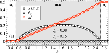
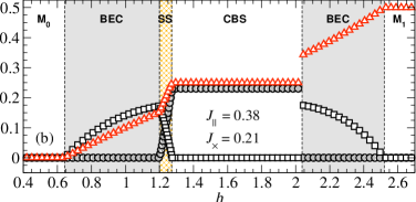
In Fig. 5 we plot these quantities as a function of the magnetic field for couplings considered in Ref. Chen et al., 2010, and . We first notice that the overall agreement between our results and the data presented in Ref. Chen et al., 2010 is remarkably good.agr For the least frustrated case of [Fig. 5(a)], the system first undergoes a quantum transition from a spin-gapped (equivalent to a trivial bosonic Mott insulator with zero-filling for triplons, in Fig. 5) to a BEC phase at the lower critical field , and then from the BEC to a fully polarized phase (trivial Mott insulator with unitary triplon filling, ) at the upper critical field . More interestingly, additional CBS and SS phases are stabilized for the more frustrated case of [Fig. 5(b)]. The existence of a SS phase at the low-field boundary of the CBS plateau, with finite values for both and is at least partially due to the presence of correlated hoppings for holes in the effective CORE Hamiltonian. Indeed, no SS phase is observed for an “effective model” obtained by setting [Fig. 3(a-b)] while keeping all the other effective couplings unchanged. This situation is to be contrasted with the first-order transition from CBS to BEC at higher fields, explained by the vanishing amplitudes for correlated hoppings for triplons for all values .
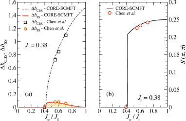
We proceed by varying the frustrating coupling while fixing . In Fig. 6(a) we plot the extent of the SS, CBS phase, respectively [ () denotes the upper (lower) boundary of the SS, CBS phase] as a function of . In order to further gauge the accuracy of the here employed CORE-SCMFT approach in Fig. 6(a) our results for and are compared against those from Ref. Chen et al., 2010 and in Fig. 6(b) we plot both our results and those from Ref. Chen et al., 2010 for the structure factor at the CBS plateau. Excellent agreement is found in both cases and we further remark that our results for in the CBS phase in Fig. 6(b) confirm that quantum fluctuations are indeed partially taken into account by SCMFT: in contrast to what happens with the semi-classical MF approach employed in Ref. Picon et al., 2008, here the value of at the plateau is somewhat reduced from its classical value .
At this point, and despite of its aforementioned attractive features, it is important to have in mind an important limitation of the here employed SCMFT procedure: since calculations rely on diagonalizations of a cluster [Fig. 4(b)], only homogeneous solutions, displaying order consistent with at most quadrupling of the unit cell, are obtainable. This excludes inhomogeneous solutions such as those associated with the presence of DWs [Fig. 1(a)] and has the consequence that our combined CORE-SCMFT approach is insensitive to the occurrence of PS. In what follows, we rely on the strong coupling analysis presented in Sec. II and analyze the interplay between PS and spin-SS order in the phase diagram of the model Eq. (3).
III.3 Phase Diagram and Phase Separation
We now turn our attention to the obtention of a global — phase diagram that may guide the experimental search for realizations of spin-supersolidity and therefore extend our analysis by varying in Eq. (3). In Fig. 7(a) we plot as a function of , obtained from the combined CORE-SCMFT procedure. These results suggest that, far from being a rare occurrence, spin-supersolidity is widespread throughout the parameter space and can extend over fairly wider ranges of than it is observed for the value [couplings considered in Ref. Chen et al., 2010 are highlighted in Fig. 7(a)]. However, under the light of our discussion in Sec. II concerning PS in systems of hard-core bosons on a lattice, some caution is required in drawing conclusions from the results shown in Fig. 7(a).
Following the discussion in Sec. II, we evaluate , our indicator for analyzing the interplay between PS and supersolidity for hard-core bosons on the square lattice, as a function of for Eq. (3). , our strong coupling estimate for the energetic gain associated to occurrence of SS order, is readily obtained by plugging the amplitudes for the leapfrog processes and [Fig. 3(a-b)] obtained from CORE into Eq. (2). On the other hand, the estimate for the energy associated to PS is obtained from numerical EDs for the simplified model for DWs defined on the “comb geometry” discussed in Sec. II.1 by using the effective ratio , as obtained from the CORE expansion for each set in Eq. (3), as an input. EDs are performed on a small cluster comprising sites ( doped holes): as mentioned in Sec. II.1, this is justified by the absence of sizable finite size effects for the data displayed in Fig. 2.
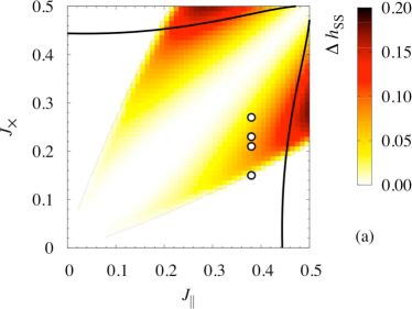
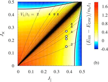
We plot as a function of in Fig. 7(b) and assume that two conditions must be simultaneously fulfilled for SS phases to exist for the model Eq. (3): (i) a SS must be observed within CORE-SCMFT and (ii) . Values of leading to , the threshold value for a SS phase to appear, are indicated by the thick continuous curve in Fig. 7. We notice that not all values of yielding a spin-SS phase within our CORE-SCMFT approach fulfill and expect PS to take place under these circumstances instead. Despite of the fact that the condition considerably shrinks the size of the region expected to support SS phases from a pure CORE-SCMFT analysis, supersolidity is still observed for a wide range of couplings in Eq. (3) [Fig. 7(a)], possibly realizable in real magnets.
Intriguingly, we notice that the parameters (circles in Fig. 7) for which a spin-SS phase has been detected by Chen et al.,Chen et al. (2010) and also by the pure CORE-SCMFT analysis devised here (Figs. 5 and 6), fail to satisfy [Fig. 7(b)]. Although we cannot exclude the possibility that our criterion, that rigorously applies only in the limit , is too stringent for the frustrated model Eq. (3), we remark that a SS phase is obtained within our CORE-SCMFT approach1st and in Ref. Chen et al., 2010 even for couplings , where our strong coupling arguments become accurate [the ratio diverges toward the line ; see Fig. 7(b), where contour levels for are plotted as thin continuous lines]. This inconsistency suggests that both CORE-SCMFT and the novel algorithm employed in Ref. Chen et al., 2010 are insensitive to the instability toward PS in systems of hard-core bosons on the square lattice and that the obtention of SS phase for is spurious.1st It would therefore be important to further test the ability of the algorithm employed in Ref. Chen et al., 2010 to detect PS in bosonic lattice models by, for instance, checking how it compares to QMC for the unfrustrated model studied in Refs. Ng and Lee, 2006; Picon et al., 2008 regarding this issue.
IV Summary
Summarizing, we have studied a spin-half frustrated bilayer model by combining CORE and SCMFT. Our results reveal the presence of a spin-SS phase under applied magnetic field, which appears at the edge of a half-saturated magnetization plateau and is stabilized by a “leapfrog mechanism”.Picon et al. (2008) We address the interplay between supersolidity and instability toward PS, that precludes the emergence of spin-SS phases, by devising a quantitative criterion based on strong coupling arguments. This criterion is generically applicable to systems of hard-core bosons on the square lattice, and it would be interesting to further assess its validity by investigating models where the interplay between PS and SS can be independently analyzed. By relying on this criterion, we obtain a global phase diagram for the frustrated spin-dimer antiferromagnet considered herein, and show that a spin-SS phase is stable against PS for couplings realizable in real magnets. We expect that our results may guide the experimental search for systems exhibiting spin-supersolidity.
Acknowledgements.
We acknowledge fruitful discussions with C. D. Batista and M. Troyer, as well as funding from the French ANR program ANR-08-JCJC-0056-01, from ARC (Australia), from the SNF and from MaNEP (Switzerland). NL acknowledges LPT Toulouse for hospitality.References
- Giamarchi et al. (2008) T. Giamarchi, C. Rüegg, and O. Tchernyshyov, Nat. Phys. 4, 198 (2008).
- Mila (1998) F. Mila, Eur. Phys. J. B 6, 201 (1998).
- Totsuka (1998) K. Totsuka, Phys. Rev. B 57, 3454 (1998); T. Giamarchi and A. M. Tsvelik, Phys. Rev. B 59, 11398 (1999).
- Sebastian et al. (2006) S. E. Sebastian, N. Harrison, C. D. Batista, L. Balicas, M. Jaime, P. A. Sharma, N. Kawashima, and I. R. Fisher, Nature 441, 617 (2006).
- Rüegg et al. (2007) C. Rüegg, D. F. McMorrow, B. Normand, H. M. Rønnow, S. E. Sebastian, I. R. Fisher, C. D. Batista, S. N. Gvasaliya, C. Niedermayer, and J. Stahn, Phys. Rev. Lett. 98, 017202 (2007).
- Krämer et al. (2007) S. Krämer, R. Stern, M. Horvatić, C. Berthier, T. Kimura, and I. R. Fisher, Phys. Rev. B 76, 100406 (2007).
- Laflorencie and Mila (2009) N. Laflorencie and F. Mila, Phys. Rev. Lett. 102, 060602 (2009).
- Takigawa and Mila (2010) M. Takigawa and F. Mila, in Introduction to Frustrated Magnetism, edited by C. Lacroix, P. Mendels, and F. Mila (Springer - Berlin, 2011).
- Kageyama et al. (1999) H. Kageyama, K. Yoshimura, R. Stern, N. V. Mushnikov, K. Onizuka, M. Kato, K. Kosuge, C. P. Slichter, T. Goto, and Y. Ueda, Phys. Rev. Lett. 82, 3168 (1999).
- Kodama et al. (2002) K. Kodama, M. Takigawa, M. Horvatić, C. Berthier, H. Kageyama, Y. Ueda, S. Miyahara, F. Becca, and F. Mila, Science 298, 395 (2002).
- Dorier et al. (2008) J. Dorier, K. P. Schmidt, and F. Mila, Phys. Rev. Lett. 101, 250402 (2008); A. Abendschein and S. Capponi, Phys. Rev. Lett. 101, 227201 (2008).
- Andreev and Lifshitz (1969) A. F. Andreev and I. M. Lifshitz, Sov. Phys. JETP 29, 1107 (1969).
- Kim and Chan (2004a) E. Kim and M. H. W. Chan, Nature 427, 225 (2004a); E. Kim and M. H. W. Chan, Science 305, 1941 (2004b).
- Balibar (2010) S. Balibar, Nature 464, 176 (2010).
- Senthil et al. (2004) T. Senthil, A. Vishwanath, L. Balents, S. Sachdev, and M. P. A. Fisher, Science 303, 1490 (2004).
- Momoi and Totsuka (2000) T. Momoi and K. Totsuka, Phys. Rev. B 62, 15067 (2000).
- Ng and Lee (2006) K.-K. Ng and T. K. Lee, Phys. Rev. Lett. 97, 127204 (2006); N. Laflorencie and F. Mila, Phys. Rev. Lett 99, 027202 (2007).
- Picon et al. (2008) J.-D. Picon, A. F. Albuquerque, K. P. Schmidt, N. Laflorencie, M. Troyer, and F. Mila, Phys. Rev. B 78, 184418 (2008).
- Sengupta and Batista (2007) P. Sengupta and C. D. Batista, Phys. Rev. Lett. 98, 227201 (2007).
- Chen et al. (2010) P. Chen, C.-Y. Lai, and M.-F. Yang, Phys. Rev. B 81, 020409 (2010).
- Morningstar and Weinstein (1994) C. J. Morningstar and M. Weinstein, Phys. Rev. Lett. 73, 1873 (1994); C. J. Morningstar and M. Weinstein, Phys. Rev. D 54, 4131 (1996).
- (22) The model Eq. (1) displays particle-hole symmetry, unlike the effective model for the spin model Eq. (3). Throughout this paper, we follow a notation similar to the one adopted in our previous work Ref. Picon et al., 2008, but omit the tildes appearing therein. That is, for instance, amplitudes for the correlated processes for holes depicted in Fig. 3 are here written as while in Ref. Picon et al., 2008 those were denoted by .
- Scalettar et al. (1995) R. T. Scalettar, G. G. Batrouni, A. P. Kampf, and G. T. Zimanyi, Phys. Rev. B 51, 8467 (1995);
- Batrouni and Scalettar (2000) G. G. Batrouni and R. T. Scalettar, Phys. Rev. Lett. 84, 1599 (2000).
- Sengupta et al. (2005) P. Sengupta, L. P. Pryadko, F. Alet, M. Troyer, and G. Schmid, Phys. Rev. Lett. 94, 207202 (2005).
- Schmidt et al. (2008) K. P. Schmidt, J. Dorier, A. M. Läuchli, and F. Mila, Phys. Rev. Lett. 100, 090401 (2008).
- Wessel and Troyer (2005) S. Wessel and M. Troyer, Phys. Rev. Lett. 95, 127205 (2005); R. G. Melko, A. Paramekanti, A. A. Burkov, A. Vishwanath, D. N. Sheng, and L. Balents, Phys. Rev. Lett. 95, 127207 (2005); D. Heidarian and K. Damle, Phys. Rev. Lett. 95, 127206 (2005); M. Boninsegni and N. Prokof’ev Phys. Rev. Lett. 95, 237204 (2005).
- Abendschein and Capponi (2007) A. Abendschein and S. Capponi, Phys. Rev. B 76, 064413 (2007).
- (29) In this way, and by imposing that each cluster’s low-energy spectrum is exactly reproduced, effective couplings of up to range-2 (see Fig. 5 in Ref. Picon et al., 2008) are computed.
- Zhao and Paramekanti (2007) E. Zhao and A. Paramekanti, Phys. Rev. B 76, 195101 (2007).
- Hassan et al. (2007) S. R. Hassan, L. de Medici, and A.-M. S. Tremblay, Phys. Rev. B 76, 144420 (2007).
- Murthy et al. (1997) G. Murthy, D. Arovas, and A. Auerbach, Phys. Rev. B 55, 3104 (1997).
- (33) Similarly good agreement is found for the other couplings considered in Ref. Chen et al., 2010, and .
- (34) A SS phase is obtained from the CORE-SCMFT procedure for arbitrarily small amplitudes for the leapfrog processes depicted in Fig. 3(a-b). First order transitions are only observed when correlated processes vanish, as it is the case for the higher-field transition out from the CBS plateau in Fig. 5(b) (correlated hoppings for triplons vanish for all ).