On computing in fine-grained
compartmentalised Belousov-Zhabotinsky medium
Abstract
We introduce results of computer experiments on information processing in a hexagonal array of vesicles filled with Belousov-Zhabotinsky (BZ) solution in a sub-excitable mode. We represent values of Boolean variables by excitation wave-fragments and implement basic logical gates by colliding the wave-fragments. We show that a vesicle filled with BZ mixture can implement a range of basic logical functions. We cascade BZ-vesicle logical gates into arithmetic circuits implementing addition of two one-bit binary numbers. We envisage that our theoretical results will be applied in chemical laboratory designs of massive-parallel computers based on fine-grained compartmentalisation of excitable chemical systems.
Keywords: Belousov-Zhabotinsky reaction, computation, logical gates, adder, excitable media, unconventional computing
1 Introduction
A reaction-diffusion computer is a spatially extended chemical system which processes information using interacting growing patterns of excitable and diffusive waves [3]. In reaction-diffusion processors, both the data and the results of the computation are encoded as concentration profiles of the reagents. The computation is performed via the spreading and interaction of wave fronts. All reaction-diffusion computers can be roughly split into two types: geometrically-constrained and free-space [6]. In geometrically-constrained computers excitation or chemical waves propagate in the ‘hardware’ of substrate defined channels and interact at the junctions between the channels. A great deal of experimental reaction-diffusion computing circuits were implemented in a geometrically-constrained media: logical gates for Boolean and multiple-valued logic [26, 23, 17, 29], many-input logical gates [15, 16], counters [13], coincidence detector [12], detectors of direction and distance to a source of periodic oscillations [14, 30] and inductive memory [23].
Free-space reaction-diffusion computers111The term ‘free-space computing’ is coined by Jonathan Mills do not have any underlying architecture. A computing medium is uniform and homogeneous, the only externally evoked disturbances of the medium’s characteristics implement computation. In majority of cases computation in free-space computers is executed using principles of a collision-based computation [2]. A collision-based computer employs mobile compact finite patterns and mobile self-localized excitations to represent quanta of information in active non-linear mediums. Information values, e.g. truth values of logical variables, are given by either absence or presence of the localizations or other parameters of the localizations. The localizations travel in space and when collisions occur the result can be interpreted as computation. There are no predetermined stationary signal channels (wires), a trajectory of the travelling pattern is a momentarily wire. Almost any part of the medium space can be used as a wire. Localizations can collide anywhere within a space sample, there are no fixed positions at which specific operations occur, nor location specified gates with fixed operations. The localizations undergo transformations, form bound states, annihilate or fuse when they interact with other mobile patterns. Information values of localizations are transformed as a result of collision [2].
So far no advanced arithmetical circuits have been implemented in free-space reaction-diffusion chemical processors. Some preparatory steps are done however. They include simulation and experimental laboratory realisation of basic logical gates [1, 4, 27] and generators of mobile localizations, excitation wave-fragments (they can play a role of constant True) in light-sensitive Belousov-Zhabotinsky (BZ) medium [8] and adaptive design of simple logical gates using machine learning techniques [28]. The main reason for such slow progress is instability of wave-fragments that either collapse or expand without external control. One-bit half-adder in geometrically-constrained light-sensitive Belousov-Zhabotinsky medium was simulated in [5], however the implementation required dynamical update of illumination level to prevent wave-fragments from collapsing or expanding. In this present paper we try to overcome the problem of excitation wave-fragments instability via combining geometrically-constraining and collision-based approaches.
The paper is structured as follows. Two-variable Oregonator model of BZ medium is introduced in Sect. 2. Section 3 outlines principles of compartmentalisation of BZ medium in planar discs and packing of the discs into a two-dimensional hexagonal lattice. Typology of interactions between wave-fragments is presented in Sect. 4. In Sect. 5 we introduce a cellular-automaton model of interacting wave-fragments. We show what types of logical gates can be realised via collision of wave-fragments in Sect. 6. These gates are employed to construct a one-bit full adder in Sect. 7. Future developments of the approach are outlined in Sect. 8.
2 Oregonator model
We use two-variable Oregonator equation [10] adapted to a light-sensitive Belousov-Zhabotinsky (BZ) reaction with applied illumination [7].
| (1) |
In framework of BZ reaction the variables and represent local concentrations of activator, or excitatory component, and inhibitor, or refractory component. Parameter sets up a ratio of time scale of variables and , is a scaling parameter depending on rates of activation/propagation and inhibition, is a stoichiometric coefficient. Constant is a rate of inhibitor production. In light-sensitive BZ represents rate of inhibitor production proportional to intensity of illumination (1).
To integrate the system we use Euler method with five-node Laplace operator, time step and grid point spacing , , , . In some cases it was enough to speed up simulation by increasing to without loss of phenomenological accuracy. The parameter characterizes excitability of the simulated medium: the medium is excitable and exhibits ‘classical’ target waves when and the medium is sub-excitable with propagating localizations, or wave-fragments, when . Time lapse snapshots provided in the paper were recorded at every 150 time steps, we display sites with .
3 Compartmentalisation
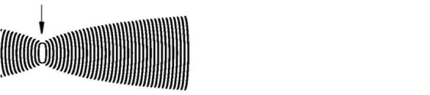
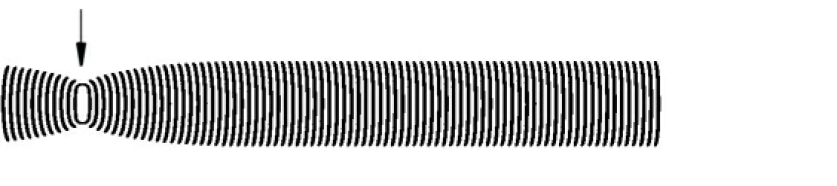
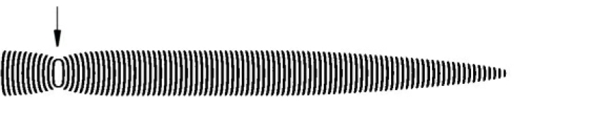
Given initial asymmetric excitation domain a wave-fragment is formed. The fragment’s velocity vector is a normal to longest side of the perturbation domain. In Fig. 1 a medium is excited by rectangular domains of perturbed sites. The perturbation domains are elongated along north-south axis therefore wave-fragments generated propagate west and east. Depending on medium’s excitability wave-fragments may expand (Fig. 1a), keep their shape for a long time (Fig. 1b) or collapse (Fig. 1c).
In ideal situation, assuming that wave-fragments keep their shapes indefinitely, we can implement a collision-based computing circuit of any depth subject to space availability. However in reality, particularly in conditions of chemical laboratory experiments, wave-fragments are very unstable. It is almost impossible to keep a medium at the precise level of sub-excitability (Fig. 1b), and almost any wave-fragment will expand (Fig. 1a) or collapse (Fig. 1c). The only solution, for controlling shape of wave-fragments, suggested so far was to change excitability of a medium periodically, as achieved in [25] in experiments with light-sensitive BZ medium. When a wave-fragment expands experimenters increase illumination level thus decreasing the medium’s excitability. When the wave-fragment starts to collapse the illumination is decreased, the medium’s excitability increases and the wave-fragment expands. This approach does not look feasible for collision-based computing [2] with excitation wave-fragments, because it requires precise synchronisation of cycles of decreasing and increasing excitability.
We can overcome the problem of wave-fragment instability by the subdividing computing substrate into interconnected compartments — BZ-vesicles — and allowing waves to collide one with another only inside the compartments. Each BZ-vesicle has a membrane impassable for excitation. A pore, or a channel, between two vesicles is formed when two vesicles come into direct contact. The pore is small such that when a wave passes through the pore there is not enough time for a wave to expand or collapse before interacting with waves entering through other pores, or sites of contact.

A spherical compartment — BZ-vesicle — is the best natural choice. It also conforms to experimental results on encapsulating excitable medium in a lipid membrane [19, 24] and allows for effortless arrangement of the vesicles into a regular lattice.
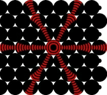
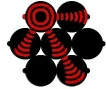
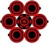
In this present paper we deal with a two-dimensional medium where vesicles are tightly packed into a hexagonal lattice (Fig. 2a). Each vesicle has radius 27 grid units, a pore has radius 5 units. The size of the vesicle and pore are critical in modulating the beam of the excitation waves. Changes in vesicle size will require further adjustment of parameter (Eq. 1) in order to maintain the ideal wave spread within the vesicle.
Each internal vesicle has six closest neighbours . Medium inside BZ-vesicles is sub-excitable while the medium outside the vesicles are non-excitable. Excitation wave-fragments propagate inside vesicles only. The waves pass from one vesicle through pores, sites of contacts.
Proposition 1.
BZ-vesicles packed in a hexagonal lattice provide a medium for directional transmission of information in a spatially extended non-linear excitable medium, where each vesicle acts as a signal amplifier and a pore, connecting two vesicles, acts as a focusing lens.
We excite the medium inside one vesicle, say , with a symmetric disc-shaped domain of perturbation centered in one of the vesicles. A circular excitation wave is formed. The circular wave reaches boundary of vesicle , and enters pores between and its neighbours (Fig. 2b). When excitation leaves a pore it has a form of a propagating wave-fragment. Due to the near-excitability of the medium (Fig. 1a) wave-fragments entering vesicles start to expand. However they do not have enough space to form a proper circular wave. Therefore they leave second-order neighbours of via one exit pore per vesicle (Fig. 2b).
4 Interaction between wave-fragments
Assumption 1.
All constructs presented in the paper assume system of BZ-vesicles is fully synchronized. Waves enter any single vesicle simultaneously.
This is a very strong and somewhat unrealistic assumption. However we use it as a starting point to build first reliable models of BZ-vesicle computers.
Proposition 2.
Let several wave-fragments enter a vesicle. If at least two wave-fragments have opposite velocity vectors all wave-fragments annihilate. Otherwise the wave-fragments merge and velocity vector of newly formed wave-fragment is a sum of velocity vectors of incoming wave-fragments.
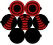
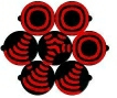
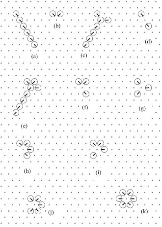
Constructive proof is illustrated by representative scenarios of wave interactions inside a single vesicle (vesicle in Fig. 2a) are shown in Fig. 3. If just one neighbour of vesicle is excited the vesicle acts as a conductor and signal amplifier: the wave simply passes through the vesicle slightly increasing in size and exits through the pore opposite to the wave’s entry pore. Thus, in Fig. 3a north-west neighbours (vesicle in Fig. 2a) is activated. Excitation enters vesicle , wave-fragment travelling south-east is formed (Fig. 3a). The wave-fragment is transmitted to south-east neighbour (vesicle in Fig. 2a) of vesicle .
There are three possible scenarios when two neighbours of vesicle are excited. In a situation when excited neighbours of are also each others closest neighbours (e.g. vesicles and in Fig. 2a) the wave-fragments generated by them merge inside vesicle (Fig. 3b). The velocity vector of a newly formed wave-fragment is a sum of vectors of two original wave-fragments. Vectors of original wave-fronts orientate towards exit pores opposite to the excitation entry pores. The vector of a newly formed wave-fragment aims between the pores, hence no excitation leaves the vesicle . For example, in (Fig. 3b) north-west and north-east neighbours of vesicle are excited. Two wave-fragments enter vesicle : one fragment travels south-east, another south-west. The wave-fragments merge and form a new wave-fragment which travels south. This fragment collides with the part of vesicle ’s wall lying between south-west and south-east pores. The fragment becomes extinguished in result of the collision.
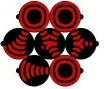
If excited neighbours of vesicle are separated by another neighbour of (e.g. vesicles and in Fig. 2a) then vector of the newly formed wave-fragment (result of merging two input wave-fragments) points exactly to one exit pore (e.g. pore connecting vesicle and vesicle in Fig. 2a). In example (Fig. 3c) north-west and east neighbours of vesicle are excited. Two wave-fragments enter vesicle : one travels south-east another travels west. They merge and form a wave-fragment travelling south-west. This fragment leaves vesicle for its southwest neighbour (vesicle ).
If wave-fragments travel towards each other (Fig. 3d) they collide and annihilate in result of the collision. Thus no excitation leaves vesicle . Scenarios of collision between three wave-fragments are shown in (Fig. 3e–g).
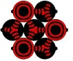
In scenarios illustrated in (Fig. 3h–k) at least two wave-fragments undergo head-on collision and all input wave-fragment annihilate. The situation (Fig. 3h) is similar to (Fig. 3c) with the only difference that three not two waves collide, however the resulting wave-fragment is the same: it travels south-west and excites south-west neighbour (vesicle ) of vesicle .
Configuration of excited neighbours shown in Fig. 3f results in annihilation of all three incoming wave-fragments. Three wave-fragments entering vesicle travel south-east, south-west and north-west. Wave-fragment travelling south-east collides head-on with wave-fragment travelling north-west. Both wave-fragments annihilate as a result of the collision. At the same wave-fragment travelling south-west collides in both south-east and south-west fragments. The south-west travelling fragment also annihilates (Fig. 3f).
Situation shown in (Fig. 3g) does correspond to direct head-on collision between wave-fragments. Three incoming wave-fragments travel south-east, west and north-east. A sum of velocity vectors of these wave-fragments is nil, therefore all fragments annihilate and no wave-fragments leave vesicle .
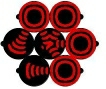
In the remaining scenarios (Fig. 3h–k) at least two incoming wave-fragments experience head-on collisions and all wave-fragments annihilate.
5 Cellular automaton representation
We simulate interactions of wave-fragments in BZ-vesicles using two-dimensional cellular automaton. The cellular automaton is a hexagonal array of cells. A cell is a finite state machine which updates its states in discrete time depending on states of its six closest neighbours. All cells update their states simultaneously.
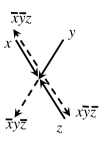
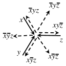
A cell takes eight states from set . They are :- resting state (), when the cell is ready to be excited, refractory state (), when the cell does not react to states of its neighbours, and six excited states representing wave-fragments. The states representing wave-fragments are coded as (south-east travelling wave), (south-west travelling wave), (westward travelling wave), (north-west travelling wave), (north-east travelling wave) and (eastward travelling wave). The excited state of a cell indicates what type of excitation wave-fragment is leaving the cell.
Let defined as follows. For every with neighbourhood (Fig. 2a): if and otherwise; if and otherwise; ; if and otherwise. Cell-state transition rule is defined as follows:
| (2) |
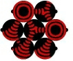
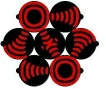
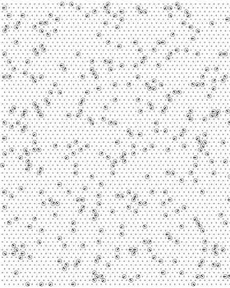
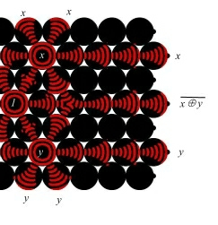
Example of the cellular automaton evolution from initial random configuration is shown in Fig. 4. In case of absorbing boundary conditions any random initial configurations leads to ‘empty’ global configuration where all cells are in resting states. This is because wave-fragment either annihilate each other (in majority of local configurations) or produce less new wave-fragments than those involved in a collision.
6 Boolean gates
We adopt principles of collision-based computing [2] to design logical gates in BZ-vesicle arrays. We assume travelling wave-fragments represent values of Boolean variables: presence of a wave-fragment in a specified site corresponds to logical True, absence to logical False. When two wave-fragments collide they annihilate or merge into a new wave-fragment. Newly formed wave-fragments represent a logical conjunction. A wave-fragment travelling along its original (undisturbed) trajectory gives us a conjunction of a logical variable represented by this wave-fragment with negation of logical variables represented by another wave-fragment.
With regards to usages of space by incoming and outgoing wave-fragments collision-based gates can be classified on gates where input and output trajectories do not overlap (Fig. 6abd) and gates where we may record output signals from inputs (Fig. 6abdf).
6.1 Gates with separate input and outputs
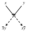
Gate (Fig. 6a) is implemented in the situation when wave-fragments incoming to a vesicle originate from the vesicles which are closest neighbours to each other (Fig. 3b and Fig. 5b). South-east travelling wave-fragment represents and south-west travelling wave-fragment represents . If just one wave-fragment, say , is present then it continues its course undisturbed, thus its outgoing trajectory symbolises . When two wave-fragments are present (true and true) they collide, form a new wave-fragment which annihilate by colliding in a vesicle wall between pores.
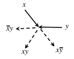
In collision scenario (Fig. 3c and Fig. 5c) wave-fragments and do not annihilate but form a new wave-fragment which travels along its own trajectory. This new wave-fragment represents conjunction . Thus we have a two-input three-output logical gate (Fig. 6b).

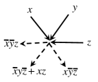
Arrangement of colliding wave-fragments shown in Fig. 3e and Fig. 5e implements three-input three-output gate (Fig. 6d). By assigning constant True to one of the inputs we can transform the gate to negation of exclusive disjunction. An implementation of the gate with collision of wave-fragments is shown in Fig. 7. This example also demonstrates that by exciting input vesicles with omnidirectional waves we multiply original signals, and copies of the signals can be employed in further gates.
6.2 Gates with spatially overlapping inputs and outputs
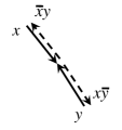
Gate shown in Fig. 6c is the simplest amongst gates with spatially overlapping trajectories of input and output wave-fragments. If =False then no wave-fragment is present in input . Therefore wave-fragment representing True travels along its original trajectory undisturbed and eventually appears on the output . The three-input, three-output gate in Fig. 6e produces its result , , on the output trajectories co-aligned with input trajectories for signals , and .
Gate Fig. 6f has three inputs and six outputs. Three outputs — , , — are represented by wave-fragments travelling outward the collision site but along the input trajectories of signals , and . Three other outputs have their own trajectories — , , and .
While it may be convenient to employ gates with spatially overlapping inputs and outputs, e.g. when space is an issue, a proper functioning of the gates will require more advanced temporal coordination of signals.
7 Towards binary adder
We employ some of the gates with spatially separated input and output trajectories to design components of one-bit binary adder. The example provided is for illustrative purposes: we did not optimize structure of logical circuits presented, neither we were concerned with number of instances of input variables used.


A binary adder based on BZ-vesicles uses collisions between propagating wave-fragments to perform addition of three one-bit binary numbers , and . The signal depict . There are many versions of particular implementations of full one-bit adder. We adopted the most common one, where the adder outputs sum of signals (Fig. 8 & Fig. 10a) and carry out value (Fig. 9 & Fig 10b).
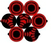
Positions of inputs in Figs. 8 and 9 are shown by thick solid circles. If an input equals False the circle contains only central dot, if the input equals True the circle contains a vector indicate the sites state. Result of sum circuit is represented by wave-fragment travelling south-east while output of carry out circuit is represented by wave-fragment travelling east. The circuit calculating is packed in array of BZ-vesicles, and the circuit calculating occupies as sub-array of BZ-vesicles. Let us discuss functioning of circuit (Fig. 8) in details.
7.1 Sum
If all three inputs are False no waves are initiated in sites and and (Fig. 8a and 10a). The wave-fragments representing constant True are placed in sites and (south-east travelling wave-fragments), and (wave-fragments travelling east). Wave-fragment collides with wave-fragment , both wave-fragments annihilate (step three of cellular automaton simulation, Fig. 8a). Wave-fragments and travel a bit further but collide one with another and annihilate at fifth step of automaton simulation. All outputs are False therefore.
If carry in value is True and other input values are False (Fig. 8a and 10b) then north-east traveling wave annihilates east travelling wave . Therefore wave continues travelling south-east, thus representing True value of .
In situation False, True, False wave collides with wave (Fig. 8c and 10a), both wave-fragments annihilate. Therefore wave-fragment continues undisturbed its travel to south-east where it collides with wave-fragment . With both waves representing east travelling constant True cancelled wave-fragment reaches an output. Similarly for input True, False, False wave-fragments and , and and annihilate in collision with each other (Fig. 8e and 10a). Therefore wave-fragment travels undisturbed. Other combinations of inputs can be considered in the similar manner.
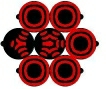
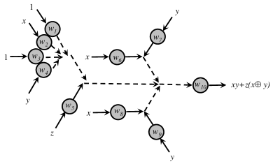
7.2 Carry out
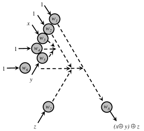
Computation starts in a group of sites marked in (Fig. 10b): site represents , site represents , and sites and represent constant True. The sub-circuits’ output is . Wave-fragments , travelling south-east, and , travelling east, are always present in the system. If only one of inputs or has True value, e.g. south-east travelling wave-front in Fig. 9ef), then wave-fragment representing this input collides with wave-fragment (constant True) and both wave-fragments annihilate. If both inputs and are True (Fig. 9gh) then waves and collide with each other and wave , merge altogether and produce new wave travelling east. This new wave (seen in node in (Fig. 9gh)) collides with wave , both wave-fragments annihilate. Thus, sub-circuit computes .
Output wave-fragment of sub-circuit collides with wave-fragment , which represents carry in value . These wave-fragments collide at angle , therefore they merge and produce new wave-fragment (travelling east) when collide. See examples in Fig. 9df. Thus intermediary result is calculated.
Two small sub-circuits — and , and and – are arranged symmetrically north and 6,6south of trajectory of wave-fragment, which represents . Each of the sub-circuits and produces . The final wave-fragment is only produced when either only wave-fragment travels east (Fig. 9df), or all three wave-fragments — wave-fragment (output of sub-circuits ) travelling south-east, wave-fragment (output of sub-circuits ) travelling north-east, and wave-fragment collide (Fig. 9h).
8 Summary
Belousov-Zhabotinsky (BZ) medium in a sub-excitable mode exhibit the rich spatio-temporal dynamics of mobile self-localisations, wave-fragments behaving as distant analogs of dissipative solitons. In an ideal situation a wave-fragment keeps its shape and travels in a predetermined direction until a collision with another wave-fragment. Therefore wave-fragments can be used as a quanta of information, or analogs of billiard vesicles [11], in developing collision-based computing circuits [2]. Our attempts to implement large scale logical circuits in experimental chemical laboratory conditions show that wave-fragments are very unstable and do not conserve their shape for a long time without external control [27, 8].
To overcome the problem of wave-fragment instability we decided to achieve a compromise between geometrically-constrained and free space approaches in designing reaction-diffusion chemical computers. In computer simulation experiments we designed a lattice of two-dimensional vesicles (BZ-vesicles) filled with BZ reaction solution. The BZ-vesicles are in close contact with each other, via tiny pores, and thus excitation wave can pass form one vesicle to its closest neighbour. Wave-fragments keep their shape or just slightly expand inside each BZ-vesicle. When a wave-fragment passes from one vesicle to another it contracts, due to the restricted size of the connecting pore.
In computer experiments we demonstrated that each BZ-vesicle, in a hexagonal arrangement of vesicles, can act as a logical gate with at most six inputs and six outputs. All basic operations of a Boolean logic are implemented via collision between wave-fragments in a vesicle and thus a lattice of BZ-vesicles is a computationally universal substrate. To show that BZ-vesicles pose not only a purely theoretical interest we cascaded the logical gates, mostly gates with two inputs and one or two outputs, in logical circuits which implement addition of two one-bit binary numbers. Functioning of the circuits was verified in cellular-automaton models of BZ-vesicle array.
Implementation of theoretical designs in chemical laboratory experiments would be the next step of our studies in fine-grained compartmentalised excitable chemical systems. Some experimental works have been done, Kitahata and colleagues provided amazing experimental evidences of excitation wave-travelling inside a tiny sphere and even movement of BZ-vesicle partly controlled by wave propagation [21, 22]. Also, BZ reaction mixture can be encapsulated via dispersion of the mixture in a water-in-oil micro-emulsion with surfactant: BZ reagents becomes enclosed in a mono-layer of anionic surfactant. ‘Unlimited’ energy supply from solution surrounding BZ-vesicles enables reactivity of BZ droplets to be sustained for extended periods of time [9].
9 Acknowledgements
The work is part of the European project 248992 funded under 7th FWP (Seventh Framework Programme) FET Proactive 3: Bio-Chemistry-Based Information Technology CHEM-IT (ICT-2009.8.3). We thank the project coordinator Peter Dittrich and project partners Jerzy Gorecki and Klaus-Peter Zauner for their inspirations and useful discussions.
References
- [1] Adamatzky A. Collision-based computing in Belousov–Zhabotinsky medium. Chaos Solitons Fractals 21 (2004) 1259–1264.
- [2] Adamatzky A. (Ed.) Collision Based Computing. Springer, 2002.
- [3] A. Adamatzky, B. De Lacy Costello, and T. Asai, Reaction Diffusion Computers (Elsevier, 2005).
- [4] Adamatzky A., and De Lacy Costello B. Binary collisions between wave-fragments in a sub-excitable Belousov-Zhabotinsky medium. Chaos, Solitons & Fractals 34 (2007) 307–315.
- [5] Adamatzky A. Slime mould logical gates: exploring ballistic approach. arXiv:1005.2301v1 [nlin.PS] (2010). http://arxiv.org/abs/1005.2301
- [6] Adamatzky A. Topics in reaction-diffusion computer. J Computational and Theor Nanoscience. (2010), in press.
- [7] Beato V., Engel H. Pulse propagation in a model for the photosensitive Belousov-Zhabotinsky reaction with external noise. In: Noise in Complex Systems and Stochastic Dynamics, Edited by Schimansky-Geier L., Abbott D., Neiman A., Van den Broeck C. Proc. SPIE 5114 (2003) 353–362.
- [8] De Lacy Costello B., Toth R., Stone C., Adamatzky A., Bull L. Implementation of glider guns in the light-sensitive Belousov-Zhabotinsky medium Phys. Rev. E 79 (2009) 026114 .
- [9] Epstein I. R. and Vanag V. K. Complex patterns in reactive microemulsions: self-organized nanostructures? Chaos 15 (2005) 047510.
- [10] Field R. J., Noyes R. M. Oscillations in chemical systems. IV. Limit cycle behavior in a model of a real chemical reaction. J. Chem. Phys. 1974 (60) 1877–1884.
- [11] Fredkin E. and Toffoli T. Conservative logic. Int J Theor Physics 21 (1982) 219- 253.
- [12] Górecka J. N., Górecki J. T-shaped coincidence detector as a band filter of chemical signal frequency, Phys. Rev. E 67 (2003) 067203.
- [13] Górecki J., Yoshikawa K. and Igarashi Y., On chemical reactors that can count, J. Phys. Chem. A 107 (2003) 1664–1669.
- [14] Górecki J., Górecka J. N., Yoshikawa K., Igarashi Y., Nagahara H. Sensing the distance to a source of periodic oscillations in a nonlinear chemical medium with the output information coded in frequency of excitation pulses. Phys. Rev. E 72 (2005) 046201.
- [15] Górecki J. and Górecka J. N., Multi-argument logical operations performed with excitable chemical medium, J. Chem. Phys. 124 (2006) 084101.
- [16] Górecki J., Górecka J. N. Information processing with chemical excitations — from instant machines to an artificial chemical brain Int J Unconv Comput 2 (2006) 321–336.
- [17] Górecki J., Górecka J. N., Igarashi Y. Information processing with structured excitable medium, Natural Computing 8 (2009) 473–492.
- [18] Górecka J. N., Górecki J., Igarashi Y. On the simplest chemical signal diodes constructed with an excitable medium, Int J Unconventional Computing 5 (2009) 129–143.
- [19] Gorecki J. Private communication (2010).
- [20] Kaminaga A., Vanag V. K., and Epstein I. R. A reaction–diffusion memory device. Angew. Chem. Int. Ed. 45 (2006) 3087- 3089.
- [21] Kitahata H., Aihara R., Magome N., and Yoshikawa K. Convective and periodic motion driven by a chemical wave. J. Chem. Phys. 116 (2002) 5666–5672.
- [22] Kitahata H. Spontaneous motion of a droplet coupled with a chemical reaction. Prog. Theor. Phys. Suppl. 161 (2006) 220–223.
- [23] Motoike I. N. and Yoshikawa K. Information operations with multiple pulses on an excitable field. Chaos, Solitons & Fractals 17 (2003) 455–461.
- [24] NeuNeu: Artificial Wet Neuronal Networks from Compartmentalised Excitable Chemical Media. (2010) http://neu-n.eu/
- [25] T. Sakurai, E. Mihaliuk, F. Chirila, and K. Showalter, Design and control of wave propagation patterns in excitable media, Science 296 (2002) 2009–2012.
- [26] Sielewiesiuk J. and Górecki J., Logical functions of a cross junction of excitable chemical media, J. Phys. Chem., A105 (2001) 8189.
- [27] Toth R., Stone C., Adamatzky A., de Lacy Costello B., Bull L. Experimental validation of binary collisions between wave-fragments in the photosensitive Belousov-Zhabotinsky reaction. Chaos, Solitons & Fractals 41 (2009) 1605–1615.
- [28] Toth R., Stone C., De Lacy Costello B., Adamatzky A., Bull L. Simple collision-based chemical logic gates with adaptive computing. J Nanotech and Molecular Computation 1 (2009) 1-13.
- [29] Yoshikawa K., Motoike I. M., Ichino T., T. Yamaguchi, Y. Igarashi, J. Gorecki and J. N. Gorecka Basic information processing operations with pulses of excitation in a reaction-diffusion system. Int J Unconventional Computing 5 (2009) 3–37.
- [30] Yoshikawa K., Nagahara H., Ichino T., J. Gorecki, J. N. Gorecka and Y. Igarashi On chemical methods of direction and distance sensing. Int J Unconventional Computing 5 (2009) 53–65.