Epitaxial strain effects in the spinel ferrites CoFe2O4 and NiFe2O4 from first principles
Abstract
The inverse spinels CoFe2O4 and NiFe2O4, which have been of particular interest over the past few years as building blocks of artificial multiferroic heterostructures and as possible spin-filter materials, are investigated by means of density functional theory calculations. We address the effect of epitaxial strain on the magneto-crystalline anisotropy and show that, in agreement with experimental observations, tensile strain favors perpendicular anisotropy, whereas compressive strain favors in-plane orientation of the magnetization. Our calculated magnetostriction constants of about ppm for CoFe2O4 and ppm for NiFe2O4 agree well with available experimental data. We analyze the effect of different cation arrangements used to represent the inverse spinel structure and show that both LSDA+ and GGA+ allow for a good quantitative description of these materials. Our results open the way for further computational investigations of spinel ferrites.
I Introduction
Spinel ferrites CoFe2O4 and NiFe2O4 are insulating magnetic oxides with high magnetic ordering temperatures and large saturation magnetizations.Brabers (1995) This rare combination of properties makes them very attractive for a wide range of applications. Recently, particular attention has been focused on the possible use of spinel ferrites as magnetic components in artificial multiferroic heterostructuresZheng et al. (2004); Zavaliche et al. (2005); Dix et al. (2007); Muralidharan et al. (2008) or as spin-filtering tunnel barriers for spintronics devices.Lüders et al. (2006a); Chapline and Wang (2006); Ramos et al. (2008)
For these applications, the corresponding materials have to be prepared either in the form of thin films, grown on different substrates, or as components of more complex epitaxial heterostructures.Suzuki (2001); Lüders et al. (2005); Zheng et al. (2004); Zhou et al. (2009) Due to the mismatch in lattice constants and thermal expansion coefficients between the thin film material and the substrate, significant amounts of strain can be incorporated in such epitaxial thin film structures, depending on the specific growth conditions and substrate materials. This epitaxial strain can then lead to drastic changes in the properties of the thin film material. Indeed, a reoriention of the magnetic easy axis under different conditions has been reported for CoFe2O4,Huang et al. (2006); Lisfi et al. (2007); Gao et al. (2009) and a strong enhancement of magnetization and conductivity has been observed in NiFe2O4 thin films.Lüders et al. (2005); Lüders et al. (2006b); Rigato et al. (2007)
In order to efficiently optimize the properties of thin film materials, it is important to clarify whether the observed deviations from bulk behavior are indeed due to the epitaxial strain or whether they are induced by other factors, such as for example defects, off-stoichiometry, or genuine interface effects. First principles calculations based on density functional theory (DFT),Hohenberg and Kohn (1964); Kohn and Sham (1965); Jones and Gunnarsson (1989) can provide valuable insights in this respect by allowing to address each of these effects separately.
Here we present results of DFT calculations for the structural and magnetic properties of epitaxially strained CoFe2O4 and NiFe2O4, with special emphasis on strain-induced changes in the magneto-crystalline anisotropy energy (MAE). Our results are representative for (001)-oriented thin films of CoFe2O4 and NiFe2O4, grown on different lattice-mismatched substrates. Our results provide important reference data for the interpretation of experimental observations in spinel ferrite thin films and in heterostructures consisting of combinations of spinel ferrites with other materials, such as perovskite structure oxides.
We find a large and strongly strain-dependent MAE for CoFe2O4, and a smaller but also strongly strain-dependent MAE for NiFe2O4. We discuss the influence of different cation arrangements within the inverse spinel structure and analyze the difference in the structural and magnetic properties due to different exchange-correlation functionals used in the calculations. From our calculations we obtain the magnetostriction constants for both CoFe2O4 and NiFe2O4, which agree well with available experimental data.
This paper is organized as follows. Sec. II.1 gives a brief overview over the properties of CoFe2O4 and NiFe2O4 that are important for the present work and also summarizes results of previous DFT calculations. The basic equations governing the magnetoelastic properties of cubic crystals are presented in Sec. II.2, followed by a detailed description of the structural relaxations performed in this work in Sec. II.3, and a summary of further computational details in Sec. II.4. The results of the bulk structural properties will be presented in Sec. III.1, whereas the effect of strain on the structural properties is analyzed in Sec. III.2. The effect of strain on the MAE is discussed in Sec. III.3. Finally, in Sec. IV a summary of our main conclusions is given.
II Background and computational details
II.1 Spinel structure and previous work on ferrites
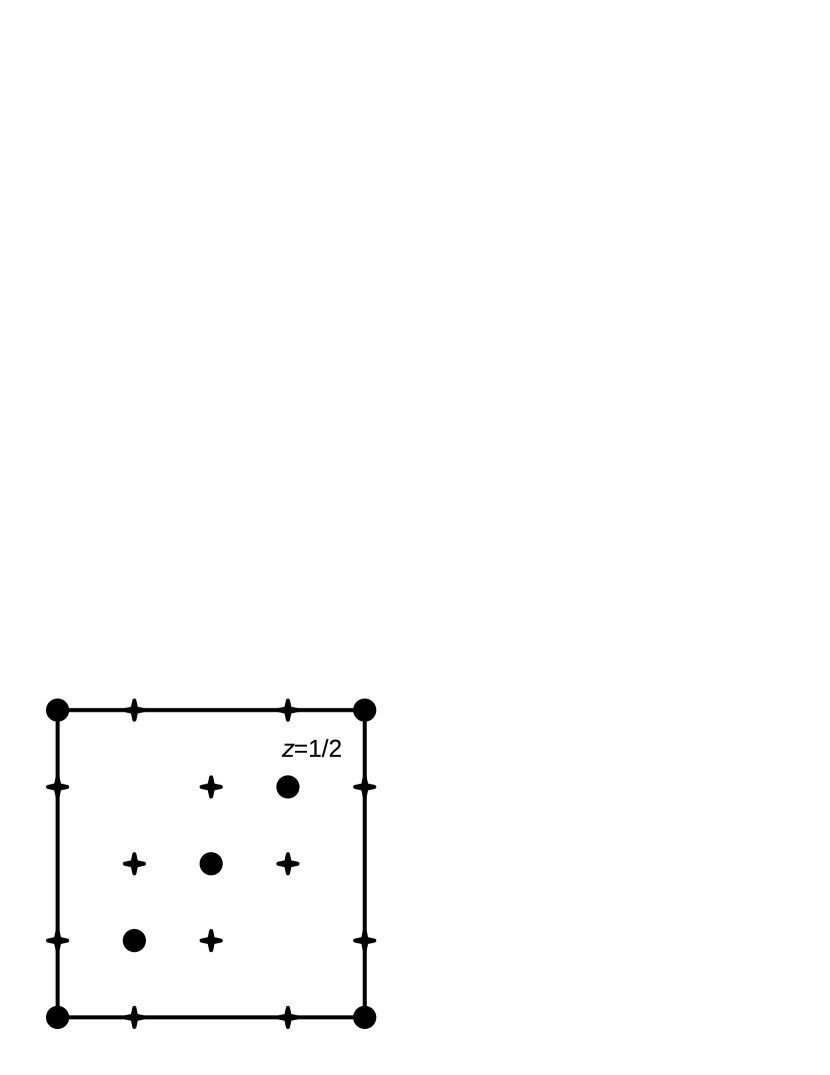
The spinel structure (space group , general formula ) contains two inequivalent cation sites, the tetrahedrally-coordinated site ( symmetry, Wyckoff position 8a), and the octahedrally-coordinated site ( symmetry, Wyckoff position 16d). In the normal spinel structure, all sites are occupied by one cation species (divalent cation), whereas all sites are occupied by the other cation species (trivalent cation). On the other hand, in the inverse spinel structure the trivalent cations occupy all sites as well as 50 % of the sites, whereas the remaining 50 % of the sites are occupied by the divalent cations. If the distribution of divalent and trivalent cations on the sites is completely random, all sites remain crystallographically equivalent and the overall cubic symmetry is preserved (see Fig. 1).
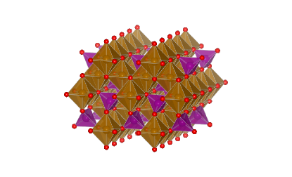
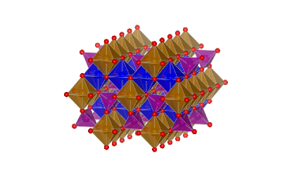
Both CoFe2O4 and NiFe2O4 crystallize in the inverse spinel structure, even though for CoFe2O4 the inversion is typically not fully complete, i.e. there is a nonzero Co2+ occupation on the site. Thereby, the exact degree of inversion depends strongly on the preparation conditions.Brabers (1995) To the best of our knowledge, no deviations from cubic symmetry have been reported for either system, i.e. the Co2+/Ni2+ cations are believed to be randomly distributed on the sites.NiF
According to the formal and electron configurations corresponding to Fe3+ and Co2+, respectively, these ions can in principle exhibit both high-spin and low-spin states, but only the high-spin states are experimentally observed in both spinel ferrites. For the electron configuration of Ni2+ no such distinction exists. The magnetic moments of the site cations are oriented antiparallel to the magnetic moments of the site cations: the so-called Néel-type ferrimagnetic arrangement.Néel (1948) Thus, the magnetic moments of the Fe3+ cations on the and sites cancel each other exactly, and the net magnetization is mainly due to the divalent site cations, i.e. either Co2+ or Ni2+. This results in a magnetic moment per formula unit close to the formal values of 3 and 2 in CoFe2O4 and NiFe2O4, respectively. Deviations from these values can be either due to orbital contributions to the magnetic moments, or due to incomplete inversion and off-stoichiometric cation distribution.
Both CoFe2O4 and NiFe2O4 are small gap insulators, but information on the experimental gap size is very limited. Waldron used infrared spectra to obtain threshold values of 0.11 eV and 0.33 eV for the electronic transitions in CoFe2O4 and NiFe2O4, respectively, Waldron (1955) whereas Jonker estimated the energy gap in CoFe2O4 to be 0.55 eV, based on resistivity measurements along with other methods.Jonker (1959)
Theoretical calculations of the electronic structure of spinel ferrites so far have been focused mostly on magnetite (Fe3O4). This material can be viewed as parent compound for the spinel ferrites, including CoFe2O4 and NiFe2O4, which are obtained by substituting the Fe2+ cation in magnetite by a different divalent 3 transition metal cation. In an early work, Pénicaud et al. performed DFT calculations within the local spin-density approximation (LSDA) for magnetite and the respective Co-, Ni-, Mn-, and Zn-substituted ferrites.Pénicaud et al. (1992) The use of LSDA leads to half-metallic band-structures for all systems except NiFe2O4, in contrast to the insulating character observed experimentally. (We note that the case of magnetite is somewhat more involved than that of the other spinel ferrites, since magnetite exhibits a metal-insulator transition at 120 K.) It was later shown by Antonov et al. that insulating solutions for Co-, Ni-, and Mn- substituted Fe3O4 can be obtained within the LSDA+ approach.Antonov et al. (2003) The same was found by Szotek et al. using a self-interaction-corrected LSDA approach.Szotek et al. (2006) The latter study also addressed the energetic difference between normal and inverse spinel structures with different valence configurations. The electronic structure of NiFe2O4 was also calculated within a hybrid functional approach, where a large band-gap of 4 eV was obtained by using 40 % of Hartree-Fock exchange in the exchange-correlation energy functional.Zuo et al. (2006) Recently, Perron et al. investigated different magnetic arrangements for NiFe2O4 in both normal and inverse spinel structures using both LSDA and the generalized gradient approximation (GGA), and found the inverse spinel structure with Néel-type ferrimagnetic order to be energetically most favorable,Perron et al. (2007) in agreement with the experimental observations.
Calculations of the MAE in strained CoFe2O4 and NiFe2O4 have been reported by Jeng and Guo.Jeng and Guo (2002a, b) However, due to the use of the LSDA, these calculations were based on half-metallic band-structures for both materials. Furthermore, no information on structural properties or the influence of the specific cation arrangement used in the calculation were given.
II.2 Magnetoelastic energy of a cubic crystal
In this work we are concerned with the effect of epitaxial strain on the structural and magnetic properties of CoFe2O4 and NiFe2O4, i.e. with the elastic and magnetoelastic response of these systems. Here, we therefore give a brief overview over the general magnetoelastic theory for a cubic crystal, and present the most important equations that are used in Sec. III to analyze the results of our first principles calculations.
The magnetoelastic energy density of a cubic crystal can be written as: Kittel (1949)
| (1) |
where the three individual terms describe the cubic (unstrained) magnetic anisotropy energy density , the purely elastic energy density and the coupled magnetoelastic contribution , respectively. To lowest order in the strain tensor and in the direction cosines of the magnetization vector, these terms have the following forms:
| (2) |
| (3) |
| (4) |
Here, denotes the lowest order cubic anisotropy constant, , , and are the elastic moduli, and and are magnetoelastic coupling constants.
The bulk modulus is defined as:
| (5) |
where is the total energy and is the equilibrium bulk volume. Using Eqs. (1)-(4) the bulk modulus of a cubic crystal can be expressed in terms of the elastic moduli and :
| (6) |
In this work we investigate the effect of epitaxial strain that is induced in thin film samples by the lattice mismatch to the substrate. This situation can be described by a fixed in-plane strain , where is the in-plane lattice constant of the thin film material and is the corresponding lattice constant in the bulk. The resulting out-of-plane strain can be obtained from Eqs. (1)-(4) together with the condition of vanishing stress for the out-of-plane lattice constant , i.e. . In the demagnetized state is related to the applied in-plane strain via the so-called two-dimensional Poisson ratio :Harrison (2005)
| (7) |
After calculating both and the bulk modulus using DFT, the elastic moduli and can thus be obtained from Eqs. (6) and (7).
In Sec. III.3 we monitor the differences in total energy for different orientations of the magnetization as a function of the in-plane constraint . Using expression (7) for and taking the energy for orientation of the magnetization along the [001] direction as reference, i.e. , one obtains:
| (8) |
Thus, the epitaxial strain-dependence of these energy differences is governed by the magnetoelastic coupling constant and the two-dimensional Poisson ratio .
Since the constant is not directly accessible by experiment, the linear magnetoelastic response is typically characterized by the magnetostriction constant , which is related to and the elastic moduli and :
| (9) |
characterizes the relative change in length (lattice constant) along [100] when the material is magnetized along this direction, compared to the unmagnetized state.
II.3 Structural relaxations for the inverse spinel structure
As described in Sec. II.1 the distribution of divalent and trivalent cations on the octahedrally coordinated sites in the inverse spinel structure is assumed to be random for both CoFe2O4 and NiFe2O4. On the other hand, the periodic boundary conditions employed in our calculations always correspond to a specific cation arrangement with perfect long-range order. Even though a “quasi-random” distribution of divalent and trivalent cations could in principle be achieved by using a very large unit cell, the required computational effort would be prohibitively large. For simplicity, we therefore restrict ourselves to the smallest possible unit cell which contains two spinel formula units, i.e. four sites. Distributing two Fe atoms on two of these sites, and filling the other two sites with either Co or Ni, lowers the symmetry from spacegroup (#227) to (#74) independent of which of the four B sites are occupied by Fe (see Fig. 1). Different choices (“settings”) simply lead to different orientations of the orthorhombic axes relative to the Cartesian directions. It will become clear from the results presented in Sec. III that the specific cation arrangement used in our calculations does not critically affect our conclusions.
Within the lower symmetry (and setting 1, see below), the tetrahedrally coordinated sites are located on Wyckoff position 4e , whereas the octahedrally coordinated sites split into Wyckoff positions 4b and 4d . In addition, the oxygen positions split into Wyckoff positions 8i and 8h .
In order to minimize the effect of this artificial symmetry lowering, and to obtain results that are as close as possible to the average cubic bulk symmetry seen in experiments, we apply the following constraints during our structural relaxations. For the calculations corresponding to the unstrained bulk case, we constrain the lattice parameters along the three cartesian direction to be equal, , and we fix the site cations to their ideal cubic positions, corresponding to . On the other hand, since the oxygen positions are characterized by one free structural parameter already within cubic symmetry (Wyckoff position 32e ), we do not apply any constraints to the 8i and 8h positions within symmetry. The relaxed bulk structure is then found by relaxing all internal positions for different volumes and finding the volume that minimizes the total energy. For the relaxations corresponding to a certain value of epitaxial strain, we constrain the two in-plane lattice constants to be equal, and then vary the out-of-plane lattice constant while relaxing all internal coordinates (except for ).
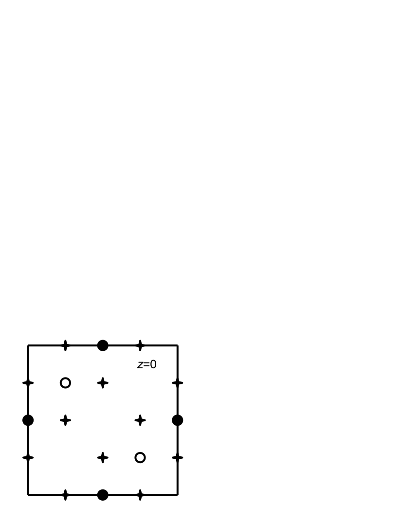
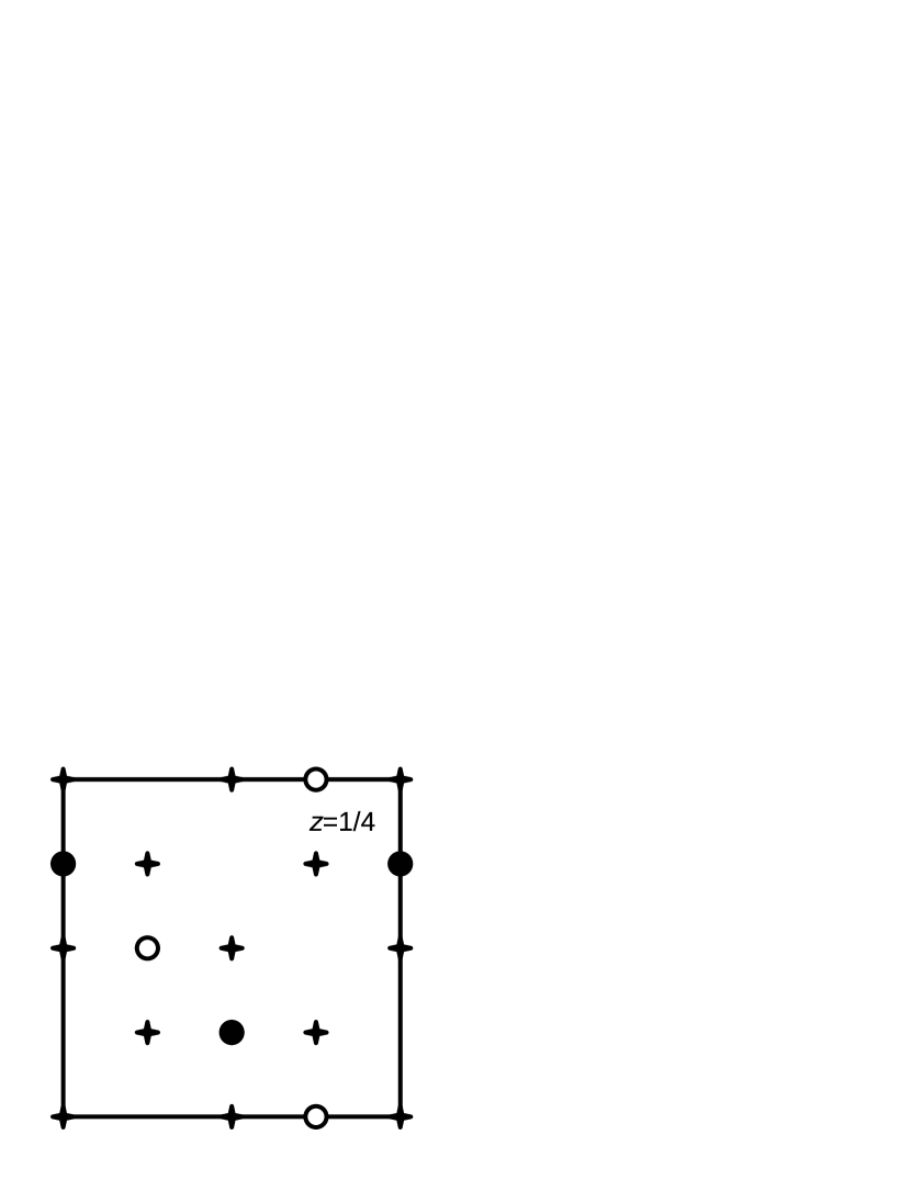
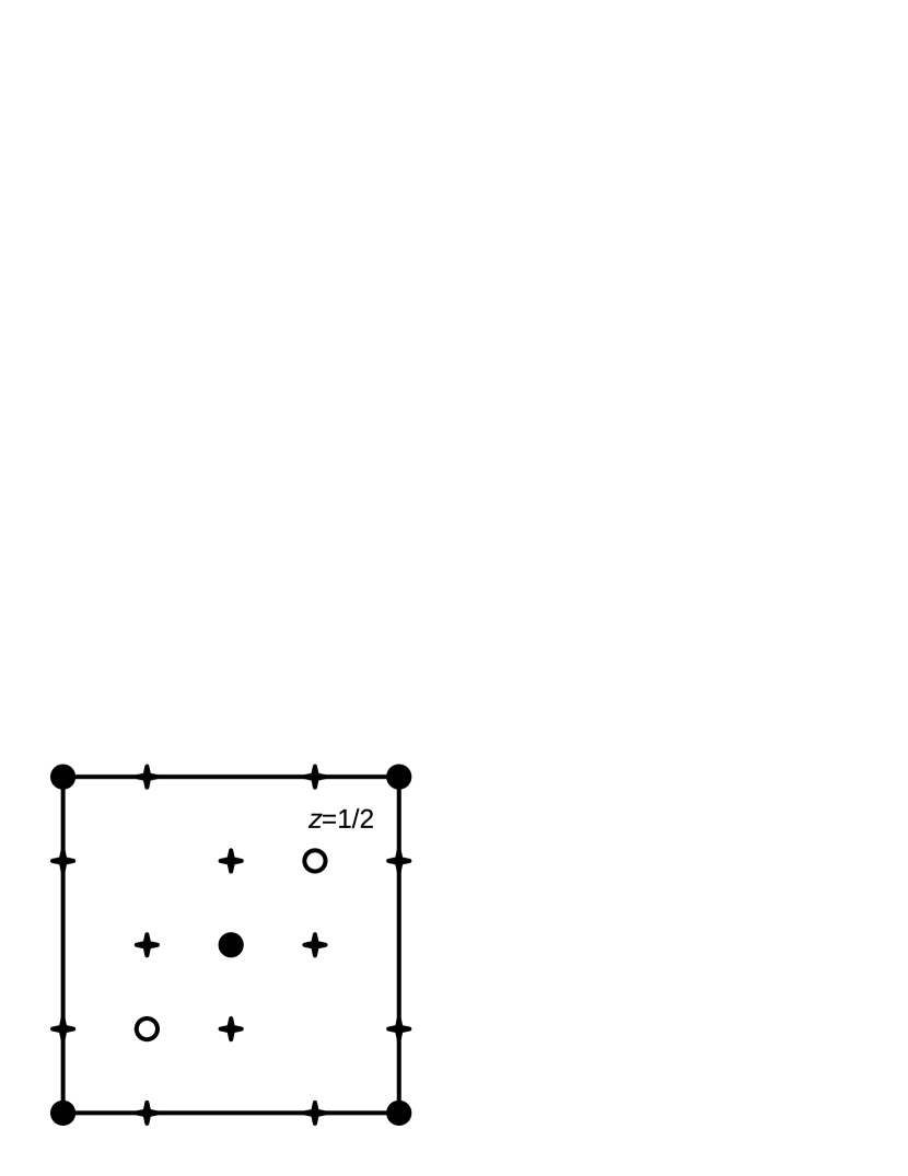
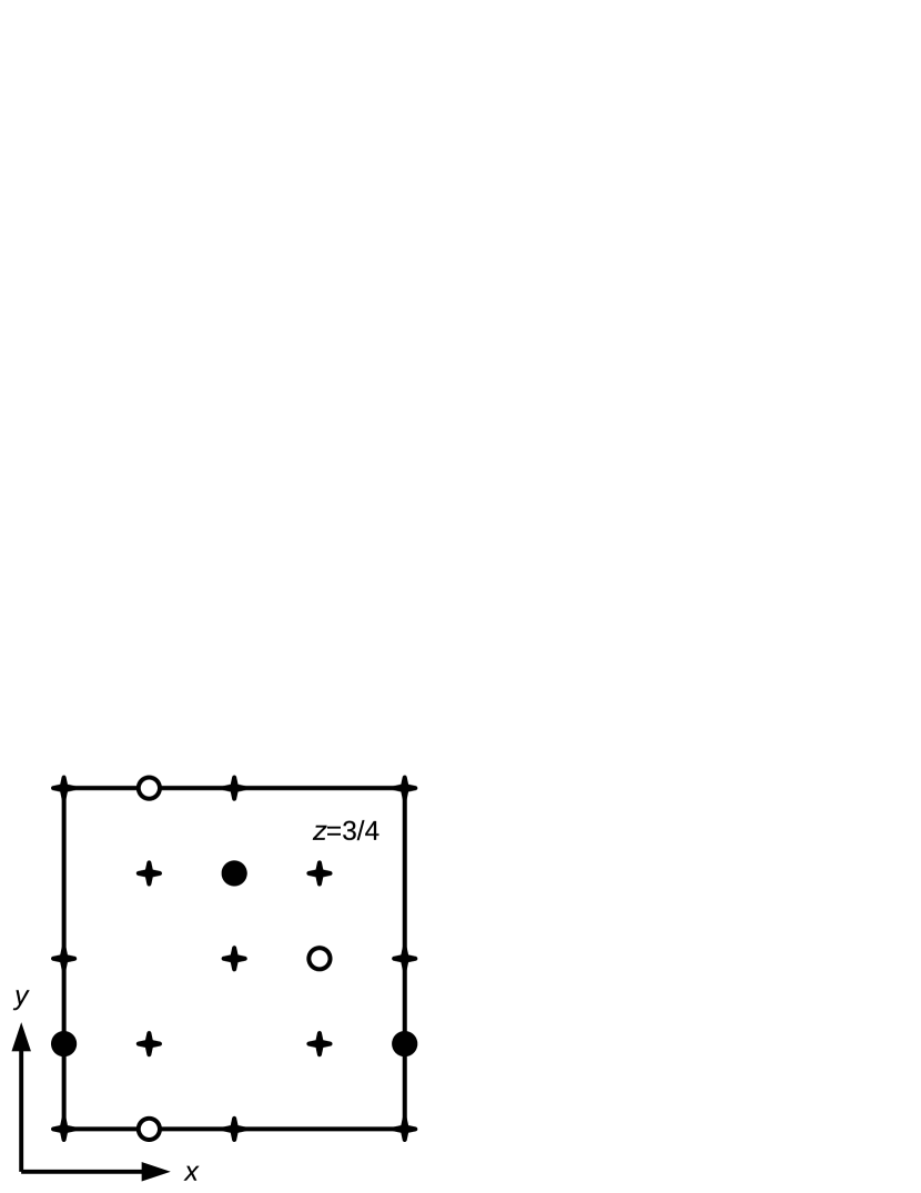
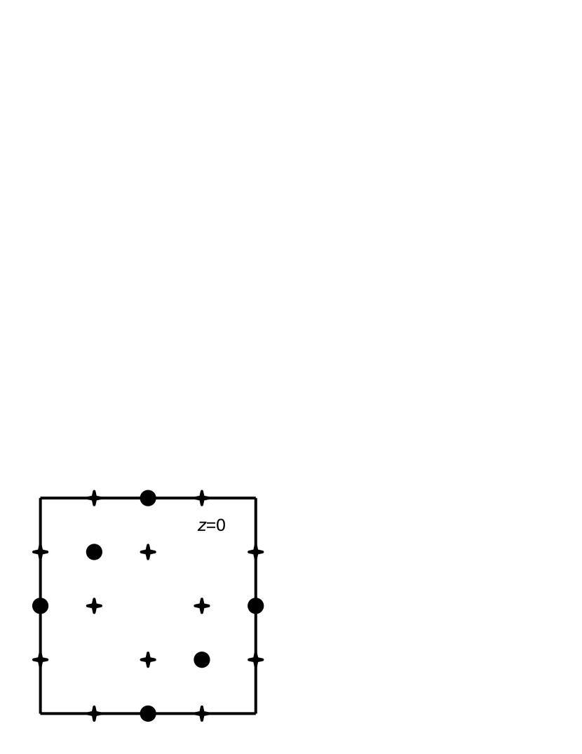
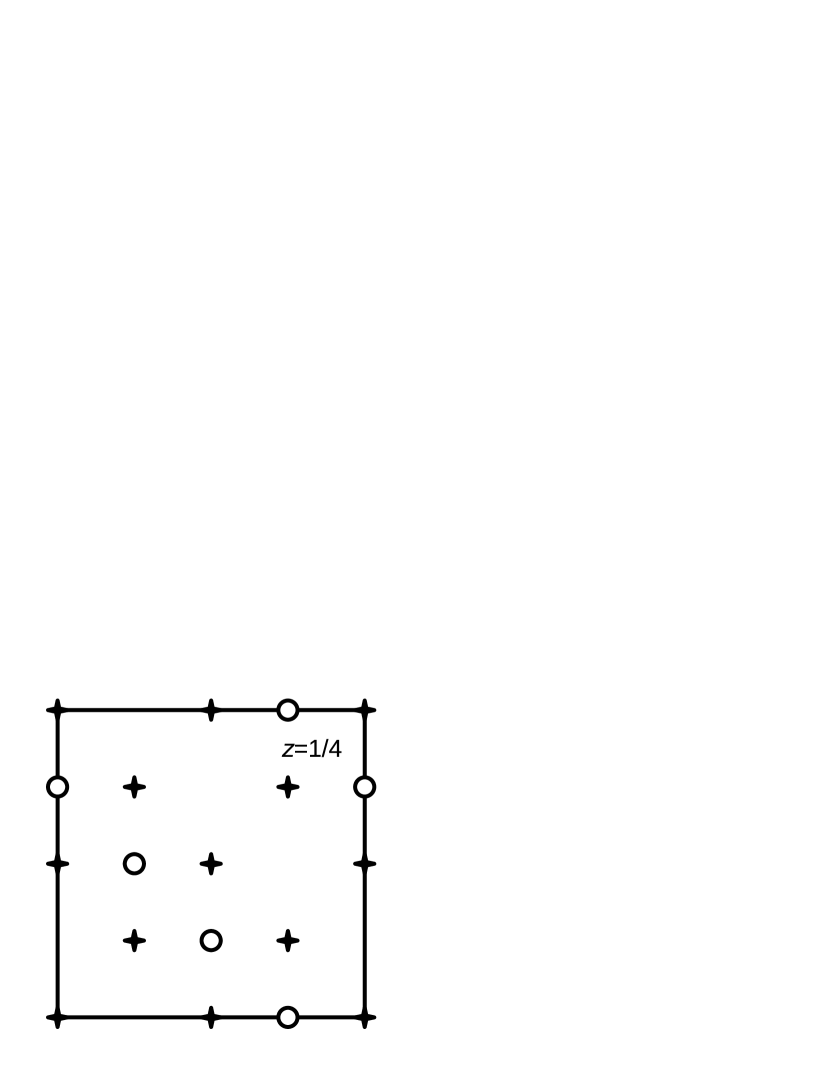
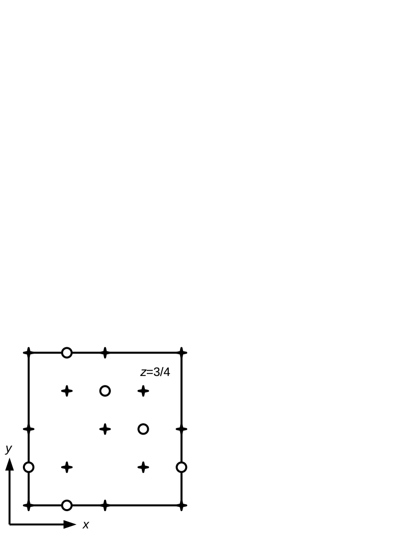
While for the unstrained bulk structure all possible site cation distributions that can be accommodated within the primitive fcc unit cell of the spinel structure lead to the same symmetry, different cases can be distinguished once an epitaxial constraint is applied to the resulting structure. To illustrate this, the cation distributions for two different settings are depicted in Figs. 2 and 2. The site cation distribution (and the oxygen positions) within different - planes are shown, corresponding to different “heights” . The different settings simply correspond to different orientations of the orthorhombic crystal axes relative to the original cubic axes.
It can be seen from Fig. 2 that the sites are arranged in an interconnected network of chains along -type directions. In setting 1 (Fig. 2), the corresponding chains within the same - plane contain alternating divalent and trivalent cations. In contrast, for setting 3 (Fig. 2) each - plane contains only one unique cation species, which then alternates between adjacent planes along the direction (see also Fig. 1). In setting 1 the same alternating planes are oriented perpendicular to the direction, whereas for setting 2 (not shown) these planes are oriented perpendicular to the direction. If an epitaxial constraint is applied within the - plane, setting 3 becomes different from settings 1 and 2, with the difference being the orientation of the “substrate plane” relative to the planes defined by the cation order.
In view of this, we have performed all calculations corresponding to epitaxially strained systems for both setting 1 and setting 3. The differences between the results obtained for the two different settings then represent a measure for the sensitivity of these results from the specific cation arrangement used in our calculations.
II.4 Other computational details
All calculations presented in this work were performed using the projector-augmented wave (PAW) method,Blöchl (1994) implemented in the Vienna ab initio simulation package (VASP 4.6).Kresse and Hafner (1993, 1994); Kresse and Furthmüller (1996a, b) Standard PAW potentials supplied with VASP were used in the calculations, contributing nine valence electrons per Co (4s23d7), 16 valence electrons per Ni (3p64s23d8), 14 valence electrons per Fe (3p64s23d6), and 6 valence electrons per O (2s22p4). A plane wave energy cutoff of 500 eV was used, and the Brillouin zone was sampled using different -point grids centered at the point. A 5 5 5 -point grid was used for the structural optimization and all total energy calculations, whereas a finer 7 7 7 grid was used to calculate densities of states (DOS). The tetrahedron method with Blöchl corrections was used for Brillouin zone integration.Blöchl (1994) We have verified that all quantities of interest, in particular the MAEs, are well converged for the used -point grid and energy cutoff. All structural relaxations were performed within a scalar-relativistic approximation, whereas spin-orbit coupling was included in the calculation of the MAEs.
As already noted in Sec. II.1, CoFe2O4 and NiFe2O4 are small gap insulators, whereas half-metallic or, in the case of NiFe2O4, only marginally insulating band-structures have been obtained in previous LSDA calculations.Pénicaud et al. (1992) In the present work we therefore use the LSDA+ and GGA+ approach,Anisimov et al. (1991) which is known to give a good description of the electronic structure for many transition metal oxides.Anisimov et al. (1997) We employ the Hubbard “+” correction in the simplified, rotationally invariant version of Dudarev et al.,Dudarev et al. (1998) where the same value eV is used for all transition metal cations. The corresponding results are compared to pure GGA calculations, using the GGA approach of Perdew, Burke, and Ernzerhof.Perdew et al. (1996) (We restricted the comparison to pure GGA since Perron et al.Perron et al. (2007) presented some evidence (for NiFe2O4) that LSDA might not be appropriate to properly describe these materials.)
Values for the local magnetic moments and atom-projected DOS are obtained by integration of the appropriate quantities over atom-centred spheres with radii taken from the applied PAW potentials (1.164 Å (Fe), 1.302 Å (Co), and 1.058 Å (Ni)), respectively.
III Results and discussion
III.1 Unstrained bulk structures
| CoFe2O4 | NiFe2O4 | |||
|---|---|---|---|---|
| [Å] | [GPa] | [Å] | [GPa] | |
| LSDA+ | 8.231 | 206.0 | 8.196 | 213.1 |
| GGA | 8.366 | 211.0 | 8.346 | 166.2 |
| GGA+ | 8.463 | 172.3 | 8.426 | 177.1 |
| Exp. (Ref. Li et al., 1991) | 8.392 | 185.7 | 8.339 | 198.2 |
| Exp. (Ref. Hill et al., 1979) | 8.35 | — | 8.325 | — |
We first present our results for the unstrained bulk structures. The calculated lattice constants and bulk moduli for both CoFe2O4 and NiFe2O4 using different exchange-correlation functionals are summarized in Table 1. It can be seen that for both CoFe2O4 and NiFe2O4 the use of LSDA+ leads to an underestimation of the lattice constant and an overestimation of the bulk modulus compared to the experimental values, whereas the opposite is the case for GGA+. The corresponding deviations (1-2 % for the lattice constants) are typical for complex transition metal oxides (see e.g. Refs. Fennie and Rabe, 2006; Neaton et al., 2005; Ederer and Spaldin, 2005).
Interestingly, the lattice constants calculated within pure GGA match the experimental values almost perfectly for both CoFe2O4 and NiFe2O4. However, this is somewhat fortuitous and probably due to a cancellation of errors, as can be seen by the large discrepancies in the bulk moduli. It will become clear in the following, that the “+” correction is necessary in order to obtain a good description of the electronic structure for both CoFe2O4 and NiFe2O4.
| CoFe2O4 | 8i | 8h | |||
|---|---|---|---|---|---|
| LDA+ | 0.235 | 0.498 | 0.009 | 0.257 | 0.255 |
| GGA | 0.240 | 0.496 | 0.008 | 0.255 | 0.255 |
| GGA+ | 0.234 | 0.499 | 0.007 | 0.259 | 0.255 |
| NiFe2O4 | 8i | 8h | |||
| LDA+ | 0.237 | 0.495 | 0.010 | 0.258 | 0.256 |
| GGA | 0.239 | 0.496 | 0.009 | 0.257 | 0.255 |
| GGA+ | 0.235 | 0.496 | 0.008 | 0.258 | 0.256 |
As discussed in Sec. II.3 the cation arrangement in our unit cell lowers the symmetry to orthorhombic , with 4 independent parameters describing the positions of the oxygen anions at Wyckoff positions 8h and 8i, compared to one parameter for Wyckoff position 32e in the cubic space group . Table 2 lists the corresponding Wyckoff parameters obtained from our structural optimizations. It can be seen that differences between different exchange-correlation functionals are rather small.
The last line in Table 2 indicates the relation between the Wyckoff positions 8i and 8h in the space group (setting 1) and Wyckoff position 32e in cubic symmetry (assuming that no actual symmetry breaking occurs). These relations allow us to obtain an average Wyckoff parameter , by calculating the value of corresponding to each of the four calculated Wyckoff parameters , , , and for each data set and subsequent averaging. The resulting values for agree very well with available experimental data, which are 0.256 for CoFe2O4 and 0.257 for NiFe2O4.Hill et al. (1979) Furthermore, the values calculated from the individual 8h and 8i Wyckoff parameters deviate only very little from the average values, which indicates that the lower symmetry used in our calculation has only a negligible effect on the internal structural parameters.
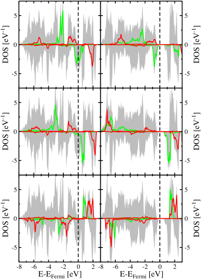
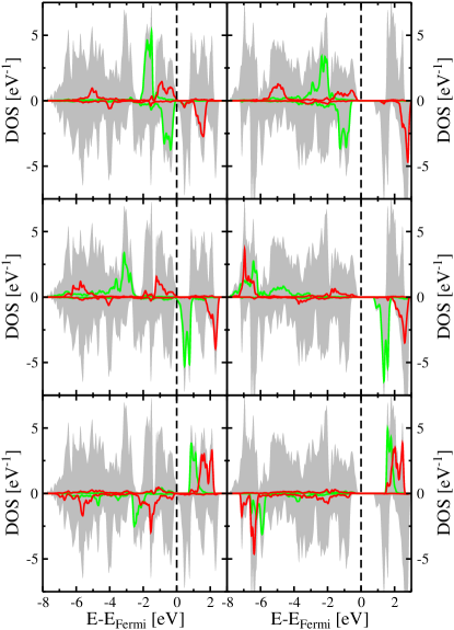
Figs. 3 and 4 show the calculated spin-decomposed densities of states (DOS) for CoFe2O4 and NiFe2O4, respectively, within the optimized bulk structure and using both pure GGA and GGA+. Both the total DOS per formula unit and the projected DOS per ion for the states of the various transition metal cations are shown, the latter separated into / and / contributions, respectively. The DOS calculated within LSDA+ (not shown) do not show any significant differences compared to the ones calculated using GGA+.
From the projected DOS it can be seen that all transition metal cations are in high spin states, with one spin-projection completely occupied, and that the cubic component of the crystal field on the octahedrally-coordinated () sites lowers the states relative to the states, whereas on the tetrahedrally-coordinated () sites the states are slightly lower in energy than the states. Due to the Néel-type ferrimagnetic order, the local majority spin direction on the sites is reversed relative to the sites.
It is apparent that within GGA CoFe2O4 turns out to be a half-metal, in contrast to the insulating behavior found in experiment.Jonker (1959) This is similar to what has been found in previous LSDA calculations.Pénicaud et al. (1992) The half-metallicity is due to the partial filling of the minority states of Co(Oh), which in turn results from the formal configuration of the Co2+ cation (see upper left panel of Fig. 3). This apparent deficiency of the GGA approach is corrected within the GGA+ calculation as can be seen in the right part of Fig. 3. We note that this is very similar to the case of rocksalt CoO, which also contains Co2+ with a electron configuration that leads to a metallic solution in pure LSDA,Terakura et al. (1984) whereas application of the DFT+ approach leads to an insulating state in agreement with the experimental observations.Anisimov et al. (1991)
The Hubbard correction splits the occupied and unoccupied parts of the minority spin states of the Co2+ cations (see upper right panel of Fig. 3), thereby opening an energy gap. In addition, the local spin splitting on the Fe cation is drastically enhanced, shifting the local majority spin states towards the bottom of the valence band. We note that once the value of on the Co sites is large enough to push the corresponding unoccupied minority spin states above the lowest minority-spin Fe() states, the width of the band gap is determined by the difference in energy between these lowest unoccupied minority-spin Fe states and the highest occupied minority spin states of Co(). Therefore, a further increase of on the Co sites does not significantly change the size of the band gap. Similarly, the band gap depends only weakly on the specific value of on the Fe sites.
The gap size of 0.9 eV obtained within GGA+ for the chosen values of is comparable to the 0.63 eV obtained by Antonov et al. using LSDA+ with =4.0 eV for the Co(Oh) and =4.5 eV for the Fe(Oh) and Fe(Td) cations,Antonov et al. (2003) and also agrees well with the value of 0.8 eV reported by Szotek et al. utilizing a self-interaction corrected LSDA approach.Szotek et al. (2006)
Ni2+ formally has one additional electron compared to Co2+, leading to a fully occupied minority spin manifold for the Ni2+ cation within a cubic () crystal field. Accordingly, NiFe2O4 exhibits a tiny gap of 0.1 eV between the occupied minority spin states of Ni() and the unoccupied minority states of Fe(Oh) even in pure GGA (see left panels of Fig. 4). However, the use of GGA+ leads to a significant enlargement of this energy gap to a more realistic value of 0.97 eV for the chosen values of . This is in good agreement with band gaps of 0.99 eV and 0.98 eV reported by Antonov et al. Antonov et al. (2003) and Szotek et al., Szotek et al. (2006) respectively. Similar to the case of CoFe2O4 the Hubbard correction also leads to a strong enhancement of the local spin splitting on the Fe sites in NiFe2O4.
| CoFe2O4 | Co() | Fe() | Fe() |
|---|---|---|---|
| LSDA+U | +2.52 | +3.99 | 3.82 |
| GGA | +2.43 | +3.66 | 3.45 |
| GGA+U | +2.62 | +4.10 | 3.98 |
| NiFe2O4 | Ni() | Fe() | Fe() |
| LSDA+U | +1.49 | +4.00 | 3.82 |
| GGA | +1.36 | +3.71 | 3.46 |
| GGA+U | +1.58 | +4.11 | 3.97 |
Table 3 shows the local magnetic moments of the transition metal cations per formula unit calculated within the three different approaches. The total magnetic moment is independent of the applied exchange-correlation functional, and equal to the integer value that follows from the formal electron configuration of the transition metal cations and the Néel-type ferrimagnetic arrangement (3 for CoFe2O4 and 2 for NiFe2O4). This is a result of the either half-metallic or insulating character of the underlying electronic structures. Nevertheless, as can be seen in Table 3, the Hubbard correction has a significant influence on the spatial distribution of the magnetization density and the use of GGA+ (and LSDA+) leads to more localized magnetic moments compared to GGA, indicated by the increased magnetic moments corresponding to the different cation sites.
The results presented in this section indicate that for a realistic and consistent description of the structural, electronic, and magnetic properties of both CoFe2O4 and NiFe2O4, a Hubbard correction to either LSDA or GGA is required. In the following we will therefore present only results obtained within the LSDA+ and GGA+ approaches.
III.2 Epitaxial strain and elastic properties
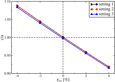
Fig. 5 shows the relaxed ratio of NiFe2O4 as function of the epitaxial constraint , obtained from GGA+ calculations as described in Sec. II.3. The case of CoFe2O4 is very similar. Two important things can be seen from this. First, due to the orthorhombic symmetry of the chosen cation arrangement on the sites, the ratio is not exactly equal to 1 at zero strain. However, this effect is clearly negligible compared to the changes in induced by epitaxial strains of order 1 % and therefore does not affect our further analysis. Second, the slope of the ratio, which characterizes the elastic response of the material, is nearly completely unaffected by the different cation arrangements.
From the data shown in Fig. 5 we can therefore obtain the 2-dimensional Poisson ratio (Eq. (7)), which relates in-plane and out-of-plane strains. Together with the bulk moduli listed in Table 1, we can then determine the two elastic constants and from Eqs. (6) and (7).
| CoFe2O4 | [GPa] | [GPa] | [GPa] | ||
|---|---|---|---|---|---|
| LSDA+ | 1 | 206.0 | 1.191 | 282.0 | 167.9 |
| 3 | 1.185 | 282.7 | 167.6 | ||
| GGA+ | 1 | 172.3 | 1.147 | 240.8 | 138.1 |
| 3 | 1.132 | 242.5 | 137.3 | ||
| Exp.Li et al. (1991) | 185.7 | 1.167 | 257.1 | 150.0 | |
| NiFe2O4 | [GPa] | [GPa] | [GPa] | ||
| LSDA+ | 1 | 213.1 | 1.172 | 294.4 | 172.5 |
| 3 | 1.167 | 295.1 | 172.2 | ||
| GGA+ | 1 | 177.1 | 1.115 | 251.2 | 140.0 |
| 3 | 1.106 | 252.2 | 139.5 | ||
| Exp.Li et al. (1991) | 198.2 | 1.177 | 273.1 | 160.7 |
The calculated 2-dimensional Poisson ratios and elastic constants and , together with the bulk moduli already presented in Table 1, are listed in Table 4, and are compared with experimental results from Ref. Li et al., 1991. It can be seen that, as already pointed out, the specific cation arrangement has nearly no influence on the value of and thus and . On the other hand, the specific choice of either LSDA+ or GGA+ has a noticeable effect. Similar to the case of the bulk modulus, we observe an overestimation (underestimation) of the elastic constants and in the LSDA+ (GGA+) calculations. The same general trend holds for the 2-dimensional Poisson-ratio of CoFe2O4, while for NiFe2O4 the use of LSDA+ also slightly underestimates . Overall the deviations are only within a few percent of the experimental data (1-2 % for CoFe2O4 and up to 6 % for NiFe2O4), and we therefore conclude that both LSDA+ and GGA+ allow for a good description of the strain response of CoFe2O4 and NiFe2O4.
III.3 Magnetoelastic coupling
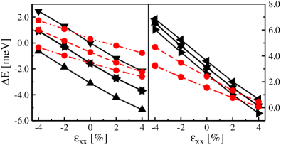
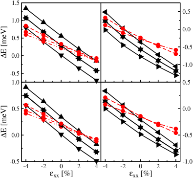
The calculated MAEs, defined as the energy differences for various orientations of the magnetization relative to the energy for orientation of the magnetization parallel to the [001] direction, are depicted in Fig. 6 for CoFe2O4 (GGA+ only) and in Fig. 7 for NiFe2O4 (both LSDA+ and GGA+). It can be seen that the calculated MAEs for CoFe2O4 are roughly five to six times larger than in NiFe2O4. Furthermore, to a good approximation, the calculated energy differences exhibit a linear dependence on strain. Deviations from this linear behavior are most pronounced for the case of NiFe2O4 within setting 3. Since the pure elastic response shown in Fig. 5 does not exhibit any significant non-linearities, we conclude that higher order magnetoelastic terms are responsible for the slightly non-linear behavior of the MAE in this case.
It can also be seen, that in all cases the strain dependence, i.e. the slope of the various curves shown in Figs. 6 and 7, is largest for the in-plane versus out-of-plane energy differences, i.e. for orientation of the magnetization along the [100], [010], [110], and [10] directions (compared to the [001] direction), consistent with Eqs. (8). Thus, tensile strain favors perpendicular anisotropy (easy axis perpendicular to the “substrate”) and compressive strain favors in-plane orientation of the magnetization, i.e. . For sufficient amount of strain the easy axis of magnetization will therefore always be oriented either in-plane or out-of-plane, consistent with various experimental observations in thin CoFe2O4 films under tensile strain. Lisfi et al. (2005, 2007); Gao et al. (2009)
According to the phenomenological magnetoelastic theory for a cubic crystal discussed in Sec. II.2, in particular Eqs. (8), the strain dependence of the in-plane versus out-of-plane anisotropy should be stronger by a factor of 2 compared to the anisotropy corresponding to [101] or [011] orientation of the magnetization, and by a factor of 3/2 compared to [111] orientation. We note that these ratios are very well observed by the calculated anisotropy energies shown in Figs. 6 and 7. This indicates that the strain-dependence of the calculated anisotropy energies is rather independent of the specific cation arrangement, which allows us to obtain the magnetoelastic constants of CoFe2O4 and NiFe2O4 from our calculations.
On the other hand, we recall that due to the specific cation arrangement used in the calculations, and the resulting symmetry lowering from cubic to orthorhombic, the three cubic axes are not equivalent even for zero strain. For setting 1 the and directions are equivalent, but different from , whereas for setting 3 and are equivalent but different from . This is reflected in the calculated anisotropy energies for zero strain (), which in setting 1 are largest between / and the direction. (Note that for zero strain both settings are completely equivalent apart from a rotation of the coordinate axes by 120∘ around the [111] direction.) The anisotropy induced by the symmetry-lowering to orthorhombic is therefore at least of the same magnitude as the cubic anisotropy in the disordered inverse spinel structure, and the calculated anisotropy energies for zero strain are therefore not representative for the inverse spinel structure with random distribution of cations on the sites, i.e. the cubic anisotropy constant cannot be determined from our calculations.
From the data shown on Figs. 6 and 7, we thus obtain the magnetoelastic coefficients by using the appropriate equation out of Eqs. (8) (together with the calculated values for ) for each calculated energy difference individually, and then average over the resulting values for within the same setting and for the same exchange-correlation functional. From the so-obtained magnetoelastic coefficients we then calculate the linear magnetostriction coefficient from Eq. (9) using the elastic moduli determined in Sec. III.2. The resulting values for both and are listed in Table 5.
| CoFe2O4 | NiFe2O4 | ||||
| B1 | B1 | ||||
| [MPa] | () | [MPa] | () | ||
| LSDA+ | 1 | — | — | 10.03 | 54.9 |
| 3 | — | — | 9.65 | 52.3 | |
| GGA+ | 1 | 29.23 | 189.7 | 6.72 | 40.3 |
| 3 | 39.74 | 251.7 | 6.08 | 35.9 | |
| Exp. | 225.0111Polycrystalline CoFe2O4 (Ref. Chen et al., 1999). | 50.9444Single crystals of NiFe2O4 (Ref. Smith and Jones, 1966). | |||
| 250.0222Single crystals with Co1.1Fe1.9O4 composition (Ref. Bozorth et al., 1955). | 36.0555Single crystals with Ni0.8Fe2.2O4 composition (Ref. Bozorth et al., 1955). | ||||
| 590.0333Single crystals with Co0.8Fe2.2O4 composition (Ref. Bozorth et al., 1955). | |||||
It can be seen that overall the calculated magnetostriction constants are in very good agreement with available experimental data, despite the difficulties related to the specific choice of cation arrangement and exchange-correlation functional. In particular the large difference in magnetostriction between CoFe2O4 and NiFe2O4 is well reproduced by the calculations. For NiFe2O4 the difference in the calculated values for due to the use of either LSDA+ and GGA+ is larger than the effect of the different cation settings. For CoFe2O4 the cation arrangement seems to have a larger influence on than for NiFe2O4. This is consistent with the large spread in the experimentally obtained magnetostriction for CoFe2O4, where different preparation conditions can lead to differences in cation distribution/inversion or slightly off-stoichiometric compositions. In addition, only very few measurements have been performed on single crystals, whereas for polycrystalline samples only a superposition of and is measured.
The rather good agreement between our calculated values for and the available experimental data demonstrates that in principle a quantitative calculation of magnetostriction in spinel ferrites is feasible, in spite of the difficulties related to the inverse spinel structure with random cation distribution on the site, and the usual difficulties regarding an accurate description of exchange and correlation effects in transition metal oxides.
IV Summary and outlook
In summary, we have presented a systematic first principles study of the effect of epitaxial strain on the structural and magneto-structural properties of CoFe2O4 and NiFe2O4 spinel ferrites. Special care was taken to assess the quantitative uncertainties resulting from different treatments of exchange-correlation effects and different cation arrangements used to represent the inverse spinel structure.
It has been shown, in agreement with earlier works, that “beyond LSDA/GGA” methods are required for a proper description of the electronic and magnetic properties of spinel ferrites CoFe2O4 and NiFe2O4. The “+” approach used in the present work leads to a realistic electronic structure and good quantitative agreement with available experimental data for lattice, elastic, and magnetostrictive constants.
We find that the specific cation arrangement used to represent the inverse spinel structure has only little effect on the structural properties. The corresponding effect on the magnetoelastic constants is also weak, with a somewhat stronger influence in the case of CoFe2O4. The latter fact is consistent with the considerable spread in the reported values for the magnetostriction constant for different samples of this material. In general, the starting point for the “+” correction, i.e. either LSDA or GGA, has a somewhat stronger influence on the calculated materials constants than the different cation settings.
However, in spite of these uncertainties, the overall agreement between our results and experimental data is very good. In particular, the calculated magnetostriction constants of about ppm for NiFe2O4 and about ppm for CoFe2O4 fall well into the spectra of available experimental values obtained from different samples (see Table 5). Consistent with the negative sign of , the easy magnetization direction changes from in-plane for compressive epitaxial strain to out-of-plane for tensile strain. This gives further confirmation that the reorientation of the easy axis observed experimentally in thin films of CoFe2O4 under different conditions is indeed predominantly strain-driven.Lisfi et al. (2005, 2007); Gao et al. (2009)
In summary, our results indicate that a quantitative description of both structural and magnetoelastic properties in spinel ferrites is possible within the DFT+ approach, which opens the way for future computational studies of these materials. Such calculations can then provide important information regarding the effect of cation inversion and off-stoichiometry, which can be used to optimize magnetostriction constants and anisotropy in spinel ferrites.
Acknowledgements.
This work was supported by Science Foundation Ireland under Ref. SFI-07/YI2/I1051 and made use of computational facilities provided by the Trinity Centre for High Performance Computing (TCHPC) and the Irish Centre for High-End Computing (ICHEC). D.F. acknowledges fruitful discussions with M. Richter and K. Koepernik.References
- Brabers (1995) V. A. M. Brabers (Elsevier, 1995), vol. 8 of Handbook of Magnetic Materials, pp. 189 – 324.
- Zheng et al. (2004) H. Zheng, J. Wang, S. E. Lofland, Z. Ma, L. Mohaddes-Ardabili, T. Zhao, L. Salamanca-Riba, S. R. Shinde, S. B. Ogale, F. Bai, et al., Science 303, 661 (2004).
- Zavaliche et al. (2005) F. Zavaliche, H. Zheng, L. Mohaddes-Ardabili, S. Y. Yang, Q. Zhan, P. Shafer, E. Reilly, R. Chopdekar, Y. Jia, P. Wright, et al., Nano Letters 5, 1793 (2005).
- Dix et al. (2007) N. Dix, V. Skumryev, V. Laukhin, L. Fàbrega, F. Sánchez, and J. Fontcuberta, Materials Science and Engineering: B 144, 127 (2007).
- Muralidharan et al. (2008) R. Muralidharan, N. Dix, V. Skumryev, M. Varela, F. Sánchez, and J. Fontcuberta, J. Appl. Phys. 103, 07E301 (2008).
- Lüders et al. (2006a) U. Lüders, G. Herranz, M. Bibes, K. Bouzehouane, E. Jacquet, J.-P. Contour, S. Fusil, J.-F. Bobo, J. Fontcuberta, A. Barthélémy, et al., J. Appl. Phys. 99, 08K301 (2006a).
- Chapline and Wang (2006) M. G. Chapline and S. X. Wang, Phys. Rev. B 74, 014418 (2006).
- Ramos et al. (2008) A. V. Ramos, T. S. Santos, G. X. Miao, M.-J. Guittet, J.-B. Moussy, and J. S. Moodera, Phys. Rev. B 78, 180402 (2008).
- Suzuki (2001) Y. Suzuki, Annu. Rev. Mater. Res. 31, 265 (2001).
- Lüders et al. (2005) U. Lüders, M. Bibes, J.-F. Bobo, M. Cantoni, R. Bertacco, and J. Fontcuberta, Phys. Rev. B 71, 134419 (2005).
- Zhou et al. (2009) S. Zhou, K. Potzger, Q. Xu, K. Kuepper, G. Talut, D. Markó, A. Mücklich, M. Helm, J. Fassbender, E. Arenholz, et al., Phys. Rev. B 80, 094409 (2009).
- Huang et al. (2006) W. Huang, J. Zhu, H. Z. Zeng, X. H. Wei, Y. Zhang, and Y. R. Li, Appl. Phys. Lett. 89, 265206 (2006).
- Lisfi et al. (2007) A. Lisfi, C. M. Williams, L. T. Nguyen, J. C. Lodder, A. Coleman, H. Corcoran, A. Johnson, P. Chang, A. Kumar, and W. Morgan, Phys. Rev. B 76, 054405 (2007).
- Gao et al. (2009) X. S. Gao, D. H. Bao, B. Birajdar, T. Habisreuther, R. Mattheis, M. A. Schubert, M. Alexe, and D. Hesse, J. Phys. D 42, 175006 (2009).
- Lüders et al. (2006b) U. Lüders, A. Barthélémy, M. Bibes, K. Bouzehouane, S. Fusil, E. Jacquet, J.-P. Contour, J.-F. Bobo, J. Fontcuberta, and A. Fert, Advanced Materials 18, 1733 (2006b).
- Rigato et al. (2007) F. Rigato, S. Estradé, J. Arbiol, F. Peiró, U. Lüders, X. Martí, F. Sánchez, and J. Fontcuberta, Materials Science and Engineering: B 144, 43 (2007).
- Hohenberg and Kohn (1964) P. Hohenberg and W. Kohn, Phys. Rev. 136, B864 (1964).
- Kohn and Sham (1965) W. Kohn and L. J. Sham, Phys. Rev. 140, A1133 (1965).
- Jones and Gunnarsson (1989) R. O. Jones and O. Gunnarsson, Rev. Mod. Phys. 61, 689 (1989).
- (20) We note that a recent preprint by Ivanov et al. available at arXiv:1005.2244 reports evidence for a short range site order in NiFe2O4.
- Néel (1948) L. Néel, Ann. Phys. (Paris) 3, 137 (1948).
- Waldron (1955) R. D. Waldron, Phys. Rev. 99, 1727 (1955).
- Jonker (1959) G. H. Jonker, J. Phys. Chem. Solids 9, 165 (1959).
- Pénicaud et al. (1992) M. Pénicaud, B. Siberchicot, C. B. Sommers, and J. Kübler, Journal of Magnetism and Magnetic Materials 103, 212 (1992).
- Antonov et al. (2003) V. N. Antonov, B. N. Harmon, and A. N. Yaresko, Phys. Rev. B 67, 024417 (2003).
- Szotek et al. (2006) Z. Szotek, W. M. Temmerman, D. Ködderitzsch, A. Svane, L. Petit, and H. Winter, Phys. Rev. B 74, 174431 (2006).
- Zuo et al. (2006) X. Zuo, S. Yan, B. Barbiellini, V. G. Harris, and C. Vittoria, Journal of Magnetism and Magnetic Materials 303, e432 (2006).
- Perron et al. (2007) H. Perron, T. Mellier, C. Domain, J. Roques, E. Simoni, R. Drot, and H. Catalette, J. Phys.: Condens. Matter 19, 346219 (2007).
- Jeng and Guo (2002a) H.-T. Jeng and G. Y. Guo, Journal of Magnetism and Magnetic Materials 239, 88 (2002a).
- Jeng and Guo (2002b) H.-T. Jeng and G. Y. Guo, Journal of Magnetism and Magnetic Materials 240, 436 (2002b).
- Kittel (1949) C. Kittel, Rev. Mod. Phys. 21, 541 (1949).
- Harrison (2005) P. Harrison, Quantum Wells, Wires and Dots: Theoretical and Computational Physics of Semiconductor Nanostructures (Wiley-Interscience, 2005), 2nd ed.
- Blöchl (1994) P. E. Blöchl, Phys. Rev. B 50, 17953 (1994).
- Kresse and Hafner (1993) G. Kresse and J. Hafner, Phys. Rev. B 47, 558 (1993).
- Kresse and Hafner (1994) G. Kresse and J. Hafner, Phys. Rev. B 49, 14251 (1994).
- Kresse and Furthmüller (1996a) G. Kresse and J. Furthmüller, Comput. Mat. Sci. 6, 15 (1996a).
- Kresse and Furthmüller (1996b) G. Kresse and J. Furthmüller, Phys. Rev. B 54, 11169 (1996b).
- Anisimov et al. (1991) V. I. Anisimov, J. Zaanen, and O. K. Andersen, Phys. Rev. B 44, 943 (1991).
- Anisimov et al. (1997) V. I. Anisimov, F. Aryasetiawan, and A. I. Liechtenstein, J. Phys.: Condens. Matter 9, 767 (1997).
- Dudarev et al. (1998) S. L. Dudarev, G. A. Botton, S. Y. Savrasov, C. J. Humphreys, and A. P. Sutton, Phys. Rev. B 57, 1505 (1998).
- Perdew et al. (1996) J. P. Perdew, K. Burke, and M. Ernzerhof, Phys. Rev. Lett. 77, 3865 (1996).
- Li et al. (1991) Z. Li, E. S. Fisher, J. Z. Liu, and M. V. Nevitt, J. Materials Science 26, 2621 (1991).
- Hill et al. (1979) R. J. Hill, J. R. Craig, and G. V. Gibbs, Phys. Chem. Minerals 4, 317 (1979).
- Fennie and Rabe (2006) C. J. Fennie and K. M. Rabe, Phys. Rev. Lett. 96, 205505 (2006).
- Neaton et al. (2005) J. B. Neaton, C. Ederer, U. V. Waghmare, N. A. Spaldin, and K. M. Rabe, Phys. Rev. B 71, 014113 (2005).
- Ederer and Spaldin (2005) C. Ederer and N. A. Spaldin, Current Opinion in Solid State and Materials Science 9, 128 (2005).
- Terakura et al. (1984) K. Terakura, T. Oguchi, A. R. Williams, and J. Kübler, Phys. Rev. B 30, 4734 (1984).
- Lisfi et al. (2005) A. Lisfi, C. M. Williams, A. Johnson, L. T. Nguyen, J. C. Lodder, H. Corcoran, P. Chang, and W. Morgan, J. Phys.: Condens. Matter 17, 1399 (2005).
- Chen et al. (1999) Y. Chen, J. E. Snyder, C. R. Schwichtenberg, K. W. Dennis, R. W. McCallum, and D. C. Jiles, IEEE Trans. Magn. 35, 3652 (1999).
- Bozorth et al. (1955) R. M. Bozorth, E. F. Tilden, and A. J. Williams, Phys. Rev. 99, 1799 (1955).
- Smith and Jones (1966) A. B. Smith and R. V. Jones, J. Appl. Phys. 37, 1001 (1966).