Quantum Hall induced currents and the magnetoresistance of a quantum point contact
Abstract
We report an investigation of quantum Hall induced currents by simultaneous measurements of their magnetic moment and their effect on the conductance of a quantum point contact (QPC). Features in the magnetic moment and QPC resistance are correlated at Landau-level filling factors and , which demonstrates the common origin of the effects. Temperature and non-linear sweep rate dependences are observed to be similar for the two effects. Furthermore, features in the noise of the induced currents, caused by breakdown of the quantum Hall effect, are observed to have clear correlations between the two measurements. In contrast, there is a distinct difference in the way that the induced currents decay with time when the sweeping field halts at integer filling factor. We attribute this difference to the fact that, while both effects are sensitive to the magnitude of the induced current, the QPC resistance is also sensitive to the proximity of the current to the QPC split-gate. Although it is clearly demonstrated that induced currents affect the electrostatics of a QPC, the reverse effect, the QPC influencing the induced current, was not observed.
pacs:
73.23.Hk, 73.23.Ra, 73.43.–fI Introduction
The occurrence of long-lived induced currents when a two dimensional electron system (2DES) is in the quantum Hall effect (QHE) regime demonstrates the extraordinarily low dissipation accompanying the effect (for a review see [Usher and Elliott, 2009]). Induced currents are expected to be present in conventional quantum Hall measurements, but are not detectable in such experiments despite often being orders of magnitude larger than the currents injected into the 2DES through the electrical contacts. This isolation of the induced currents from the edge states that cause the conventional QHE has led to the suggestionKlaffs et al. (2004) that the induced currents flow within the innermost of the incompressible strips proposed by Chklovskii et al. (1992) However, we recently discovered that induced currents can influence conventional transport measurements in electrostatically defined nanostructures such as quantum point contacts (QPCs) or quantum dots.Pioro-Ladrière et al. (2006) Features were observed in the conductance of a QPC and the Coulomb blockade spectrum of a quantum dot which were hysteretic with respect to magnetic-field sweep direction. In the same work, separate experiments measuring the magnetic moment associated with the QHE induced currents showed that they were present in the same GaAs heterojunction from which the nanostructures were fabricated. The filling-factor, temperature, and sweep-rate dependences of the induced currents in the heterojunction correlated with the hysteretic behaviour observed within the nanostructures, suggesting that a common origin was possible. In this paper we report the first simultaneous measurements of induced currents from their magnetic moments and their effects on QPC conductance, confirming their common origin and demonstrating that the QPC resistance is sensitive not only to the magnitude of the induced current but also to its distance from the QPC split-gate.
II Experiment details
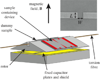
The device was fabricated at the Institute for Microstructural Sciences,AK (4) from a GaAs–(Al,Ga)As heterojunction, forming a 2DES of dimensions by with a metallic split-gate defined on the surface, approximately 110 nm above the 2DES. The split gate was centred over the 2DES. The lithographic dimensions of the gate are given in Fig. 1. The QPC was defined electrostatically by the application of a negative bias, with respect to the 2DES, to both sides of the split gate. Gold ohmic contact pads on the QPC were connected to insulated copper twisted pairs (25 µm diameter with approximately 3 twists per millimetre) with colloidal-silver paint.Sil The device was mounted on the rotor of a torsion-balance magnetometer (Fig. 1); details are given elsewhere.Matthews et al. (2004) The normal to the 2DES was tilted at an angle of to the applied magnetic field. The wires from the device were arranged to minimise mechanical perturbation of the magnetometer.

In order to reduce noise, predominantly manifest as telegraph noise,Pioro-Ladrière et al. (2005) the sample was cooled from room temperature with a gate voltage of applied. This removed free charge from the gate region whilst it was still mobile. A standard four-terminal measurement with a low-frequency (17.3 Hz) lock-in detector was used to determine the QPC resistance, with an excitation current of . Once cold, the gate voltage was set to a negative value such that conduction through the QPC was below , and hence the mechanism for conduction was quantum tunnelling. In this state the QPC was very sensitive to changes in its local electrostatic environment. With this arrangement, simultaneous measurements were made of the magnetic moment of the induced current in the regions of 2DES either side of the QPC, and of the conduction through the QPC.
The magnetometer occupied the mixing chamber of a dilution refrigerator and measurements were taken between and . The magnetic field was produced by a solenoid, driven by an Oxford Instruments IPS 120-20 digital power supply.
III Results
III.1 Simultaneous measurements of magnetic moment and QPC resistance
Figure 2 shows the results of the simultaneous measurement of the magnetic moment and the QPC resistance. Evidence of induced currents (features that reverse with magnetic-field sweep direction) are seen at Landau-level filling factors and in both the magnetic moment and the QPC resistance data. The smaller features in the magnetic moment at and are primarily caused by capacitive coupling between the 2DES and the capacitor plates (the shield referred to in Fig. 1 was designed to minimise this coupling), but on close inspection also show a small hysteretic effect.
The relative sizes of the features and for the magnetic moment are approximately , while for the QPC magnetoresistance features they are . We suggest two possible explanations for this difference. First, the QPC measurement is influenced not only by the size of the induced current but also, very strongly, by the distance of the current path from the edge. This distance increases as decreases (i.e. as the magnetic length increases), reducing the sensitivity of the QPC to the induced current. Second, the sensitivity of the QPC depends on the background resistance, which is changing with magnetic field due to a background magnetoresistance. These two explanations are not mutually exclusive.

III.2 Temperature dependence
Figure 3 shows the temperature dependence of the two measurements at at a relatively high sweep rate of . The widths of the hysteretic features in both measurements reduce monotonically with increasing temperature, while the heights remain approximately constant up to a temperature of and then gradually reduce as the temperature is increased further. For (not shown) the region of constant feature-height persists up to 800 mK. There is a significant difference, of about , in the magnetic fields at which the magnetic moment and resistance features occur, and there is a significant asymmetry to the resistance curves. These are not experimental artefacts, and will be discussed below.

III.3 Sweep-rate dependence
Figure 4 shows the sweep-rate dependences of the magnetic moment and the hysteretic QPC resistance features at and 4. These measurements are effectively current–voltage (–) curves for the induced currents: the sweep rate is proportional to the electromotive force around the perimeter of the 2DES, and the magnetic moment or QPC resistance is proportional to the induced current. Both – curves show a saturation of the induced current at magnetic-field sweep rates greater than . For , saturation occurs at the lowest sweep rate used, , which corresponds to an electromotive force of . For a more gradual reduction in the induced current is observed. In both cases the shapes of the – curves derived from the two simultaneous measurements are the same within experimental error.

III.4 Noise
Figure 5 shows the induced current feature for for both magnetic moment and QPC resistance using a very slow sweep rate of . Under these conditions previous investigators Elliott et al. (2006) observed a qualitatively reproducible ‘noise’ structure around the induced current peaks which they attributed to local QHE breakdown events occurring at various positions around the perimeter of the 2DES. In Fig. 5 several ‘noise’ features (e.g. those marked by arrows) appear in both measurements providing the strongest evidence to date that the two effects have a common cause. The fact that the noise features have similar sizes in both measurements lends support to the suggestionKlaffs et al. (2004) that the induced current forms one loop around the entire 2DES, rather than many loops localised by impurities.
Although the noise features occur at the same magnetic fields, the peaks of the induced current features (peak M in the magnetic moment and peak R in the QPC resistance) do not coincide, as noted earlier in Section III.2. The QPC resistance peak R is shifted to higher magnetic field than the magnetic moment peak M. This clearly demonstrates that the QPC measurement is not simply measuring the size of the induced current (as the magnetic moment measurement does) but is also sensitive to other factors. Evidently the QPC conductance is influenced by the proximity of the induced current to the QPC as well as its size, as suggested in Section III.1 above. This proximity is related to the magnetic length. Therefore features in the QPC resistance will tend to shift to higher magnetic field compared with those in the magnetic moment – a higher field results in a smaller magnetic length, and hence an induced current closer to the QPC.

III.5 Decays
Figure 6 shows the decay of the induced current when the magnetic field is swept to filling factors and and then held constant, measured simultaneously from its magnetic moment and its effect on QPC resistance. At both the magnetic moment and the QPC resistance show a rapid initial decay lasting approximately s, followed by a much longer period of slower-than-exponential decay. The QPC resistance also appears to exhibit some drift in the opposite direction to the decay. At the magnetic moment decay behaves in the same way as at but for the QPC resistance the slow-decay regime is replaced by a faster approximately linear decay. At (not shown) the decay of both the magnetic moment and the QPC resistance is rapid and appears to be exponential. The trend towards faster decays at higher filling factors is due to the decrease in Landau-level separation, (where ), as increases. We note here that although is a spin-split feature (and hence the energy between the highest occupied and the lowest unoccupied Landau level is ), the process by which the decay occurs probably involves tunnelling, which one would expect to conserve spin – thus the levels involved in the tunnelling are separated by an energy , not . We attribute the difference in behaviour of the long-time decays at to the sensitivity of the QPC resistance to the proximity of the induced current as well as its size – as the induced current decays, the Hall electric field supporting it is also reduced and the induced current becomes more spread out into the bulk of the 2DES. This effect is not apparent at because the current does not decay sufficiently for spreading to become noticeable.
IV Discussion and Conclusions
The observations discussed above show that induced currents cause the hysteretic features in both the magnetic moment and the QPC resistance. We have also investigated the reverse effect, whether the QPC can be used to influence the induced current. For instance, during an induced-current decay, the bias on the QPC split gate was repeatedly changed to alternately pinch off the QPC and then open it to the point where the 2DES number density under the gate matched that in the bulk of the device. The expectation was that this would cause some extra dissipation and hence increase the decay rate. No such effect was observed. In another experiment different voltages were applied to the two sides of the split gate, with the aim of setting up counter-propagating induced currents in close proximity, again with the expectation of enhanced dissipation. None was apparent. Further studies are necessary to determine how induced currents can be controlled by electrostatically defined nanostructures.
To conclude, in this paper we have demonstrated that the hysteretic features observed in the magnetoresistance of a QPC and the hysteretic features detected in the magnetic moment of the 2DES surrounding the device have a common origin – they are caused by long-lived induced currents which occur in the dissipationless regime of the quantum Hall effect. We have shown this by making simultaneous measurements of the two effects on the same QPC device, and correlating the features, their temperature and sweep-rate dependences and their decays. We have also identified common features in the reproducible ‘noise’ structure observed at low sweep rates. It is clear that induced currents are responsible for both effects; however a close comparison of the two measurements suggests that the hysteretic magnetoresistance of the QPC is sensitive not only to the size of the induced currents but also to their proximity to the QPC.
Acknowledgements.
The authors would like to thank K. White for constructing the torsion-balance magnetometer, and M. Elliott and R.J. Nicholas for helpful discussions. This work was supported by EPSRC.References
- Usher and Elliott (2009) A. Usher and M. Elliott, Journal of Physics, Condensed Matter, 21, 103202 (2009).
- Klaffs et al. (2004) T. Klaffs, V. A. Krupenin, J. Weis, and F. J. Ahlers, Physica E: Low-dimensional Systems and Nanostructures, 22, 737 (2004).
- Chklovskii et al. (1992) D. B. Chklovskii, B. I. Shklovskii, and L. I. Glazman, Physical Review B, 46, 4026 (1992).
- Pioro-Ladrière et al. (2006) M. Pioro-Ladrière, A. Usher, A. S. Sachrajda, J. Lapointe, J. Gupta, Z. Wasilewski, S. Studenikin, and M. Elliott, Physical Review B, 73, 75309 (2006).
- AK (4) Institute for Microstructural Sciences, NRC-CNRC Canada, sample designation ‘AK47’.
- (6) Silver paint: (Silver in Methyl Isobutyl Ketone) Manufacturer brand: Acheson Electrodag 1415M. Distributed by Agar Scientific (product number G3648), batch no. 0334. Agar Scientific, Essex, CM24 8DA, UK.
- Matthews et al. (2004) A. J. Matthews, A. Usher, and C. D. H. Williams, Review of Scientific Instruments, 75, 2672 (2004).
- Pioro-Ladrière et al. (2005) M. Pioro-Ladrière, J. H. Davies, A. R. Long, A. S. Sachrajda, L. Gaudreau, P. Zawadzki, J. Lapointe, J. Gupta, Z. Wasilewski, and S. Studenikin, Physical Review B, 72, 115331 (2005).
- Elliott et al. (2006) M. Elliott, Y. Lu, K. L. Phillips, W. G. Herrenden-Harker, A. Usher, A. J. Matthews, J. D. Gething, M. Zhu, M. Henini, and D. A. Ritchie, Europhysics Letters, 75, 287 (2006).