Magnetic interaction at an interface between manganite and other transition-metal oxides
Abstract
A general consideration is presented for the magnetic interaction at an interface between a perovskite manganite and other transition metal oxides. The latter is specified by the electron number in the level as . Based on the molecular orbitals formed at the interface and the generalized Hund’s rule, the sign of the magnetic interaction is rather uniquely determined. The exception is when the orbital is stabilized in the interfacial manganite layer neighboring to a or system. In this case, the magnetic interaction is sensitive to the occupancy of the Mn orbital. It is also shown that the magnetic interaction between the interfacial Mn layer and the bulk region can be changed. Manganite-based heterostructures thus show a rich magnetic behavior. We also present how to generalize the argument including orbitals.
pacs:
73.20.-r,75.70.-iI Introduction
Transition metal (TM) oxides have been one of the main subjects of materials science for decades. Experimental and theoretical efforts are driven by their rich, complex, and potentially useful behaviors originating from strong correlations between electrons and/or electrons and lattices.Imada98 The recent developments in the crystal growth techniques, in particular the (laser) molecular-beam epitaxy, have made us recognize the opportunity to further control their behaviors and to generate phenomena that are not realized in the bulk systems.Izumi01 ; Ohtomo02 ; Ohtomo04 ; Okamoto04 ; Stahn05 ; Chakhalian06 ; Hoffmann05 ; Chakhalian07 ; Bhattacharya08
Here, we focus on the magnetic behavior at an interface between perovskite manganite and other TM oxides. Perovskite manganites, especially La1-xSrxMnO3 (LSMO), are particularly important because of their ferromagnetic (F) metallic behavior with relatively high Curie temperature and large polarization. Controlling the magnetic interaction at interfaces involving manganites would cause a technological breakthrough for electronic devices using, for example, a tunneling magnetoresistance (TMR) effectBowen03 ; Ogimoto03 and an exchange bias (EB) effect.Yu09 This requires the microscopic information on the orbital states, not only on the spin states as demonstrated for cuprate/manganite interfaces in Refs. Chakhalian07, and Veenendaal08, . However, it remains controversial whether the magnetic moment is induced in the cuprate regionChakhalian06 ; Veenendaal08 or the dead layers appear in the manganite region.Hoffmann05 ; Luo08
The difficulty dealing with interfaces involving strongly-correlated electron systems comes from the small volume fraction which makes the experimental analysis challenging, and strong-correlation effects which hinder some of theoretical treatments. Therefore, if a Goodenough-Kanamori-type Goodenough63 ; Kanamori59 transparent description of the interfacial magnetic interaction becomes available, both experiment and theory would greatly benefit.
In this paper, we present a general consideration for the magnetic interaction at an interface involving manganites. We first focus on the interfacial interaction derived by orbitals which have the largest hybridization along the layer-stacking direction. We see that the sign of the magnetic interaction via the orbitals is naturally fixed based on the molecular orbitals formed at the interface and the generalized Hund’s rule. The argument uses localized orbitals, and therefore shows only the qualitative trend. The molecular orbitals effectively lift the degeneracy between and orbitals by the order of the hopping intensity. In the second part, we perform the model Hartree-Fock calculation and show that the broken degeneracy can lead to the additional change in the magnetic interaction between the interfacial Mn layer and its neighboring Mn layer. We also discuss how to generalize the molecular-orbital based argument for more complicated situations including orbitals.
II Molecular-orbital picture
In this section, we consider the magnetic interaction between manganite and other TM oxides focusing on the molecular orbitals formed by orbitals which have the largest overlap at the interface. The TM region is specified by the number of electrons occupying a orbital. Here, electrons are assumed to be electronically inactive and considered as localized spins when finite number of electrons occupy orbitals. Generalization including these electrons will be discussed later.
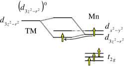
system. Let us start from the simplest case, an interface between Mn and a system (Fig. 1). In this case, the bonding (B) orbital is occupied by an electron whose spin is parallel to the localized spin in Mn, while the antibonding (AB) orbital is unoccupied. When there are other unpaired electrons in the system at and/or orbitals, their spins align parallel to that of the electron in the B orbital due to the Hund coupling. Thus, the F coupling is generated between Mn and systems. This is equivalent to the double-exchange (DE) interaction originally proposed by Zener.Zener51 When is much lower in energy than and in the interfacial Mn layer (termed order), Mn and systems are virtually decoupled. Thus, the magnetic coupling is due to the superexchange (SE) interaction between electrons. This interaction is either F or antiferromagnetic (AF) depending on the orbital state and the occupancy of the TM level.
normal. This simple consideration can be easily generalized to and systems. First we consider that the and are nearly degenerate in the interfacial Mn layer and the unoccupied level in the TM region is much higher than the level (Fig. 2, top figures). We call this configuration “normal” (N) configuration. In the lowest energy configuration, B orbitals and the Mn orbital are occupied by electrons. For the system, the F interaction is favorable as in the system. On the other hand, for the system, the down electron orbital is hybridized with the minority band in the Mn region. Thus, the “down” B orbital is higher in energy and has larger weight on the TM than the “up” B orbital. Because of the Hund coupling with the “down” electron in the B orbital, other unpaired electrons, if they exist in and/or orbitals, tend to be antiparallel to the Mn spin.
Since orbitals are predominantly occupied in the interfacial Mn layer due to the B/AB splitting of -based molecular orbitals, further stabilization of orbitals in the Mn region, i.e., order, would not affect the interfacial magnetic coupling discussed here. But, this could reverse the magnetic coupling between the interfacial Mn layer and the second Mn layer as discussed in the next section.
anomalous. When the level in the TM region becomes lower than the Mn level, the charge transfer occurs. We shall call this configuration “anomalous” (AN) configuration (Fig. 2, middle figures). The electron transferred to the TM orbital has the same spin as the higher energy B orbital due to the Hund coupling (indicated by arrows). Therefore, the sign of the magnetic coupling between the Mn and systems is unchanged.
Note that this argument is applicable when the hopping probability between orbitals in the Mn and the TM regions is negligibly small. The finite hopping probability would make the charge transfer continuous. Furthermore, when the hopping probability becomes large, the DE interaction is generated. Although the DE interaction through bonds may not be realistic, it cooperatively stabilizes the F spin alignment for the case, while it competes with the AF tendency for the case.
Magnetic interactions discussed so far are insensitive to the electron density in the interfacial Mn because the interactions are mainly derived from the virtual electron excitation from the occupied orbital in the TM region to the unoccupied counterpart in the Mn region.
Next, we consider that the level is much lower than the in the interfacial Mn layer due to either the local Jahn-Teller distortion or compressive strain originating from the substrate (Fig. 2, lower figures denoted by “JT”). The magnetic coupling in this case is sensitive to the electron density of the interfacial Mn.
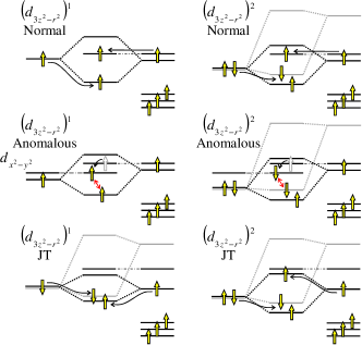
JT. When the Mn density is close to 1, the SE interaction between the occupied orbitals becomes AF. On the other hand, when the density is much less than 1, the F interaction between configuration on Mn and becomes dominant.
JT. When the Mn occupancy is close to 1, “up” electrons are localized on each sites because both B and AB molecular orbitals are occupied while down electrons can be excited or leaked from the system to the Mn minority level, i.e., down electron density is virtually reduced in the TM region. As a result, unpaired spins, if they exist in and/or orbitals, become parallel to the up spin, i.e., F coupling. When the Mn density becomes much less than 1, the up AB orbital becomes less occupied while keeping the occupancy of B orbitals relatively unchanged. Eventually, the down density in the TM region becomes larger than the up density, and the magnetic coupling between the Mn and regions becomes AF.
III Model Hartree-Fock analysis
In the previous section, we discussed the interfacial magnetic coupling controlled by the molecular orbitals. The separation between B and AB molecular levels can become as large as the order of , the hybridization between orbitals along the direction. Since the interfacial Mn band is represented by the B (AB) orbital for a /manganite interface, the degeneracy is effectively lifted in the interface layer. This degeneracy lifting is expected to affect the magnetic interaction in the Mn region. In this section, we discuss this effect using the microscopic model calculation.
We consider a two-band DE model given by
| (1) | |||||
Here, an electron annihilation operator at site and orbital is given by , , and the level difference between and is given by . We consider the large Hund coupling limit, in which the spin direction of a conduction electron is always parallel to that of a localized spin on the same site, and omit the spin index. Instead, the relative orientation of spins is reflected in the hopping matrix; is the unitary transformation representing the rotation of the spin direction between sites and . For simplicity, we only consider nearest-neighboring (NN) hoppings between Mn orbitals via oxygen in the middle. Using the Slater-Koster scheme,Slater54 the orbital dependence of is written as , , , and . The third term represents interorbital Coulomb interaction. Due to the symmetry, is related to the intraorbital Coulomb interaction and the interorbital exchange integral as . The last term represents the AF SE interaction between NN spins .
From the optical measurements, the on-site interactions are estimated as eV and eV.Kovaleva04 The density-functional theory calculation provides eV.Ederer07 Using the mean-field analysis for the Néel temperature of CaMnO3, one estimates meV.Wollan55 A similar value is obtained from the magnon excitations in the A-AF phases of 50 % doped Pr1-xSrxMnO3 and Nd1-xSrxMnO3 supposing that the AF interaction is due to the same .Kawano03 Thus, in what follows, we take . Considering some ambiguity, the realistic value for is expected to be –0.05.
We analyze the model Hamiltonian, Eq. (1), using the Hartree-Fock approximation at focusing on the doped region (carrier density far away from 1). In light of the experimental reports, we compare the energy of the following eight magnetic orderings: F ordering, planar AF ordering in which spins align ferromagnetically in the ( or ) plane [A (A’)], chain-type AF ordering in which spins align ferromagnetically along the ( or ) direction [C (C’)], zigzag AF in which spins form ferromagnetic zigzag chains in the ( or ) plane [CE (CE’)], and NaCl-type AF (G). At , in addition to the spin symmetry breaking, orbital symmetry can be broken due to the SE mechanism in the present model.Kugel82 Since we are focusing on the metallic regime , we do not consider such a symmetry breaking.
The numerical results for the bulk phase diagram are presented in Figs. 3 (a)-3 (c). Here, all phase boundaries are of first order, and those at small can be replaced by canted AF phases or the phase separation between the undoped G-AF phase and doped F or AF phases. The overall feature is consistent with the previous theoretical reports.Maezono98 ; Brink99a ; Fang00 At , A-AF and A’-AF (C- and C’-, CE- and CE’-) are degenerate but the degeneracy is lifted by the finite . We found the CE phase at at and (not shown) as in the previous reports.Solovyev99 ; Brink99b ; Brey05 At , the CE phase becomes unstable against A- and C-AF phases and appears only at the positive with . reproduces the phase diagram of a high system such as LSMO and Pr1-xSrxMnO3 (Refs. Jirak01, and Chmaissem03, fairly well.
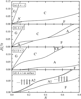
The main effect of the level separation is changing the stability of planar-type AF (A or A’) with respect to the chain-type AF (C or C’) and F states. In particular, the A-AF phase is stabilized by the positive more strongly than the C-AF phase by the negative . This is because the energy gain by the DE mechanism is favorable for the A-AF than the C-AF. The result is semiquantitatively consistent with the previous report based on the density-functional theory.Fang00 At , the boundary between F and A-AF phases is moved down to at . This behavior suggests that, when the AB level for the /manganite interfaces is about higher than the Mn level, the magnetic coupling between the interfacial Mn and the second Mn layers is switched to AF while retaining the intraplane F coupling.
We confirmed this behavior by computing the surface phase diagram considering F phase and two AF phases: A1(2) where the surface layer (and the second layer) is antiferromagnetically coupled to its neighbor. We introduce positive only on the surface layers in the 20-layer slab. As shown in Fig. 3 (d), a large part of F phase is replaced by A1 phase compared with the bulk phase diagram (b). (Precise phase boundary requires detailed information of the surface or interface.) Although the parameter regime is small, it is also possible that surface three layers are AF coupled while the other couplings remain F, A2 phase, before the whole system enters A-AF when is increased or is decreased. When the orbital is stabilized, the inter-Mn-layer coupling remains F but the intraplane F coupling is reduced. Therefore, in-plane canted AF structure may result for small .
IV Summary and discussion
Summarizing, we presented a general consideration on the magnetic interaction between the doped manganite and other transition metal oxides when an interface is formed. Using the molecular orbital formed at the interface and the generalized Hund’s rule, the sign of the magnetic interaction is determined (Sec. II). The bonding/antibonding splitting of the molecular orbitals leads to the degeneracy lifting of orbitals on the interface Mn layer. Further, the bulk strain lifts the degeneracy. These effects control the magnetic interaction in the interfacial Mn plane and between the interfacial Mn plane and its neighbor (Sec. III). Considering these effects, we summarized the magnetic couplings in /manganite interfaces in Table 1. Although the present argument is rather qualitative, it is physically transparent and can be applied to a variety of systems. It is also straightforward to generalize the argument to include other orbitals. Therefore, the present argument will also help a more quantitative analysis with detailed information from either the experiment or the first principle theory.
| Condition | TM-Mn(1) | Mn(1)-Mn(1) | Mn(1)-Mn(2) | |
|---|---|---|---|---|
| 0 | N & JT | F | F* | F |
| N w/ order | AF | F | AF | |
| 1 | N | F | F | F* |
| N w/ order | F | F | AF | |
| AN | F | F* | F* | |
| JT w/ | AF | F* | F | |
| JT w/ small | F | F* | F | |
| 2 | N | AF | F | F* |
| N w/ order | AF | F | AF | |
| AN | AF | F* | F* | |
| JT w/ | F | F* | F | |
| JT w/ small | AF | F* | F |
It is worth discussing the implication of the present results to the real systems. An example of the system is high- cuprate. It has been reported that the magnetic coupling between YBa2Cu3O7 (YBCO) and La1-xCaxMnO3 is AF,Chakhalian06 and and in the interfacial Cu have a similar amount of holes.Chakhalian07 This corresponds to the AN situation. F coupling due to the DE remains in the Mn region because of the finite band width of . An example of the system is BiFeO3 (BFO). Recently, the EB effect was reported at BFO/LSMO interfaces accompanying the “AF” coupling between BFO and LSMO.Yu09 We expect the N situation with ordering at this interface. Although the interfacial coupling is F, the AF coupling between the interfacial Mn and the second Mn layers results in the AF alignment between BFO and bulk LSMO as observed experimentally and is responsible for the exchange bias effect.
A question one may ask is what causes the “AN situation” in YBCO and the “N situation” in BFO? A qualitative explanation is as follow: in YBCO, the unoccupied Cu state is right above the Mott gap and its position is nearly identical to the occupied band of manganites.Yunoki07 Therefore, the charge transfer from Mn to Cu can easily occur. On the other hand, the high-spin state is realized in BFO, and the unoccupied state with opposite spin with respect to the majority electrons is located far above the gap. In addition, the very close chemical potentials (i.e. close levels) of BFO (Ref. Paradis05, ) and LSMO (Ref. Jong03, ) maximize the B and AB splittings. This situation is favorable for the ordering in the interfacial Mn layer and the resulting AF coupling between the first and the second Mn layers [see Fig. 3 (d)].
Finally, an example of the system may be non-magnetic SrTiO3, and the coupling with this is expected to affect the magnetic state near the interfacial Mn. For small doping of LSMO, the coupling with SrTiO3 (with the smaller lattice constant of SrTiO3) increases the orbital occupancy suppressing the inplane DE effect. For large doping, SrTiO3 creates the tensile strain stabilizing , and the out-of-plane F coupling is reduced.Ogimoto03 Both are expected to cause a more rapid decrease in the ordered moment with increasing temperature than in the bulk region,Okamoto09 resulting in the rapid suppression of the TMR effect in LSMO/SrTiO3/LSMO junctions.Bowen03 ; Ogimoto03 The in-plane (out-of-plane) spin canting may also be realized in the former (latter).Ogimoto03 For undoped LaMnO3, the out-of-plane ferromagnetic coupling may result because the overlap between the occupied in the first Mn layer and the unoccupied or orbitals in the second Mn layer is increased, favorable for the F SE interaction between Mn layers.
However, since orbitals in titanates are located near (slightly above) the Fermi level of manganite,Yunoki07 one may need to consider orbitals more carefully as discussed below.
Extention to systems. In systems such as titanates, vanadates, and cromates, coupling between orbitals could become as important as the coupling between orbitals. Here, we discuss how to generalize the molecular-orbital argument presented in Sec. II to systems. As an example, we consider an interface between titanate with the configuration and manganites. Extending the argument to other systems is straightforward.
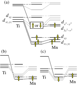
Figure 4 (a) shows the level diagram of the titanate/manganite interface including both and orbitals. For simplicity, only bonding orbitals are presented. Because the level in titanate is far above the occupied levels in manganite and the unoccupied levels in titanate and manganite (down electrons for the latter) are close,Yunoki07 highest occupied molecular orbitals could be either B up or orbital [Fig. 4 (b) which is equivalent to Fig. 1] or B down orbitals [Fig. 4 (c)]. Note that the interfacial hybridization between orbitals on Ti and Mn is much smaller than those between and between .
In the case of Fig. 4 (b), induced moment in the titanate region is tiny but parallel to the moment in manganite region. On the other hand in the case of Fig. 4 (c), the induced moment in the titanate region could be either parallel or antiparallel to the manganite moment. This depends on the relative weight of the down electron density in the B orbitals with respect to the up electron density in the B orbitals. The situation in Fig. 4 (c) with antiparallel spin arrangement between titanate and manganite could happen when the original electron density in the manganite orbital is large and level both in titanate and manganite is high due, for example, to the in-plane tensile strain. But in general, the difference between two configurations, Figs. 4 (b) and 4 (c) with either parallel or antiparallel spin configurations, would be subtle. Therefore, depending on a variety of condition such as the sample preparation, any situation could be realized.
When the number of electrons is increased, such as doped titanates, vanadates, and cromates, electrons tend to enter the down B orbitals and, then, the down B , resulting in the antiparallel spin configuration. However, the antiparallel configuration becomes unstable against the parallel configuration when the electron number in orbitals becomes large and the level separation between and orbitals, i.e., , becomes relatively small.
In this case, because of the strong on-site Coulomb interactions, the energy gain by forming B orbitals becomes small for electrons and comparable to having electrons in both B and AB orbitals with the parallel spin configuration. The parallel configuration further lowers the energy by forming B orbital and by the Hund coupling between the B orbital and electrons on the system, i.e., the Zener’s double-exchange ferromagnetism discussed in Sec. II.
When there are more than three electrons with relatively large , a low spin state is realized. In this case, three electrons enter B orbitals formed with minority bands of Mn and remaining electrons enter AB orbitals formed with majority band of Mn. Thus, the antiparallel configurations persist. Such a situation may be realized in, for example, an interface between manganites and SrRuO3 in which Ru4+ is in a low spin state with . This AF configuration can be turned to the F configuration when the double-exchange-type interaction becomes dominant due to the formation of B orbital.Panagopoulos10
So far, we have considered the ideal lattice structure in which orbitals with different symmetry do not hybridize. In reality, bond angle formed by two transition metal ions and an oxygen ion in between becomes smaller than 180∘ allowing electrons to hop between orbitals with different symmetry. As a result, additional magnetic channels are generated. A simple argument presented in this paper can be generalized to deal with such a situation.
Acknowledgements.
The author thanks P. Yu, R. Ramesh, J. Santamaria, and C. Panagopoulos for stimulating discussions and sharing the experimental data prior to publication, J. Kuneš for discussion, and the Kavli Institute of Theoretical Physics, University of California Santa Barbara, which is supported in part by the National Science Foundation under Grant No. PHY05-51164, for hospitality. This work was supported by the Materials Sciences and Engineering Division, Office of Basic Energy Sciences, U.S. Department of Energy.References
- (1) M. Imada, A. Fujimori, and Y. Tokura, Rev. Mod. Phys. 70, 1039 (1998).
- (2) M. Izumi, Y. Ogimoto, Y. Konishi, T. Manako, M. Kawasaki, and Y. Tokura, Mater. Sci. Eng., B 84, 53 (2001).
- (3) A. Ohtomo, D. A. Muller, J. L. Grazul, and H. Y. Hwang, Nature (London) 419, 378 (2002).
- (4) S. Okamoto and A. J. Millis, Nature (London) 428, 630 (2004).
- (5) A. Ohtomo and H. Y. Hwang, Nature (London) 427, 423 (2004); A. Brinkman, M. Huijben, M. van Zalk, J. Huijben, U. Zeitler, J. C. Mann, W. G. van der Wiel, G. Rijnders, D. H. A. Blank, and H. Hilgenkamp, Nature Mater. 6, 493 (2007); N. Reyren, S. Thiel, A. D. Caviglia, L. Fitting Kourkoutis, G. Hammerl, C. Richter, C. W. Schneider, T. Kopp, A.-S. Rüetschi, D. Jaccard, M. Gabay, D. A. Muller, J.-M. Triscone, and J. Mannhart, Science 317, 1196 (2007).
- (6) J. Stahn, J. Chakhalian, C. Niedermayer, J. Hoppler, T. Gutberlet, J. Voigt, F. Treubel, H.-U. Habermeier, G. Cristiani, B. Keimer, and C. Bernhard, Phys. Rev. B 71, 140509(R) (2005).
- (7) J. Chakhalian, J. W. Freeland, G. Srajer, J. Strempfer, G. Khaliullin, J. C. Cezar, T. Charlton, R. Dalgliesh, C. Bernhard, G. Cristian, H.-U. Habermeier, and B. Keimer, Nat. Phys. 2, 244 (2006).
- (8) A. Hoffmann, S. G. E. te Velthuis, Z. Sefrioui, J. Santamaría, M. R. Fitzsimmons, S. Park, and M. Varela, Phys. Rev. B 72, 140407 (R) (2005).
- (9) J. Chakhalian, J. W. Freeland, H.-U. Habermeier, G. Cristiani, G. Khaliullin, M. van Veenendaal, and B. Keimer, Science 318, 1114 (2007).
- (10) A. Bhattacharya, S. J. May, S. G. E. te Velthuis, M. Warusawithana, X. Zhai, B. Jiang, J.-M. Zuo, M. R. Fitzsimmons, S. D. Bader, and J. N. Eckstein, Phys. Rev. Lett. 100, 257203 (2008).
- (11) M. Bowen, M. Bibes, A. Barthélémy, J. P. Contour, A. Anane, Y. Lemaîtrem, and A. Fert, Appl. Phys. Lett. 82, 233 (2003).
- (12) Y. Ogimoto, M. Izumi, A. Sawa, T. Manako, H. Sato, H. Akoh, M. Kawasaki, and Y. Tokura, Jpn. J. Appl. Phys., Part 2 42, L369 (2003).
- (13) P. Yu, J.-S. Lee, S. Okamoto, M. D. Rossell, M. Huijben, C.-H. Yang, Q. He, J.-X. Zhang, S. Y. Yang, M. J. Lee, Q. M. Ramasse, R. Erni, Y.-H. Chu, D. A. Arena, C.-C. Kao, L. W. Martin, and R. Ramesh, Phys. Rev. Lett. 105, 027201 (2010).
- (14) M. van Veenendaal, Phys. Rev. B 78, 165415 (2008).
- (15) W. Luo, S. J. Pennycook, and S. T. Pantelides, Phys. Rev. Lett. 101, 247204 (2008).
- (16) J. B. Goodenough, Magnetism and the Chemical Bond (Interscience, New York, 1963).
- (17) J. Kanamori, J. Phys. Chem. Solids 10, 87 (1959).
- (18) C. Zener, Phys. Rev. 82, 403 (1951).
- (19) J. C. Slater and G. F. Koster, Phys. Rev. 94, 1498 (1954).
- (20) N. N. Kovaleva, A. V. Boris, C. Bernhard, A. Kulakov, A. Pimenov, A. M. Balbashov, G. Khaliullin, and B. Keimer, Phys. Rev. Lett. 93, 147204 (2004).
- (21) C. Ederer, C. Lin, and A. J. Millis, Phys. Rev. B 76, 155105 (2007).
- (22) E. O. Wollan and W. C. Koehler, Phys. Rev. 100, 545 (1955).
- (23) H. Kawano-Furukawa, R. Kajimoto, H. Yoshizawa, Y. Tomioka, H. Kuwahara, and Y. Tokura, Phys. Rev. B 67, 174422 (2003).
- (24) K. I. Kugel’ and D. I. Khomskii, Sov. Phys. Usp. 25, 231 (1982).
- (25) R. Maezono, S. Ishihara, and N. Nagaosa, Phys. Rev. B 58, 11 583 (1998).
- (26) J. van den Brink and D. Khomskii, Phys. Rev. Lett. 82, 1016 (1999).
- (27) Z. Fang, I. V. Solovyev, and K. Terakura, Phys. Rev. Lett. 84, 3169 (2000).
- (28) I. V. Solovyev and K. Terakura, Phys. Rev. Lett. 83, 2825 (1999).
- (29) J. van den Brink, G. Khaliullin, and D. Khomskii, Phys. Rev. Lett. 83, 5118 (1999).
- (30) L. Brey, Phys. Rev. B, 71, 174426 (2005).
- (31) Z. Jirák, J. Hejtmánek, E. Pollert, C. Martin, A. Maignan, B. Raveau, and M. M. Savosta, J. Appl. Phys. 89, 7404 (2001).
- (32) O. Chmaissem, B. Dabrowski, S. Kolesnik, J. Mais, J. D. Jorgensen, and S. Short, Phys. Rev. B 67, 094431 (2003).
- (33) S. Yunoki, A. Moreo, E. Dagotto, S. Okamoto, S. S. Kancharla, and A. Fujimori, Phys. Rev. B 76, 064532 (2007).
- (34) P.-F. Paradis, T. Ishikawa, and S. Yoda, Meas. Sci. Technol. 16, 452 (2005).
- (35) M. P. de Jong, V. A. Dediu, C. Taliani, and W. R. Salaneck, J. Appl. Phys. 94, 7292 (2003).
- (36) S. Okamoto, J. Phys.: Condens. Matter 21, 355601 (2009).
- (37) J. W. Seo, W. Prellier, P. Padhan, P. Boullay, J.-Y. Kim, H. G. Lee, C. D. Batista, I. Martin, E. E. M. Chia, T. Wu, B.-G. Cho, and C. Panagopoulos, arXiv:1006.3603 (unpublished).