Klein tunneling of light in fiber Bragg gratings
Abstract
A photonic analogue of Klein tunneling (KT), i.e. of the exotic property of relativistic electrons to pass a large repulsive and sharp potential step, is proposed for pulse propagation in a nonuniform fiber Bragg grating with an embedded chirped region. KT can be simply observed as the opening of a transmission window inside the grating stop band, provided that the impressed chirp is realized over a length of the order of the analogue of the Compton wavelength.
I Introduction
A remarkable prediction of the Dirac equation is that a below-barrier electron can pass a large repulsive and sharp potential step without the exponential damping expected for a non-relativistic particle. Such a transparency effect, originally predicted by Klein Klein and referred to as Klein tunneling (KT), arises from the existence of negative-energy solutions of the Dirac equation and requires a potential step height of the order of twice the rest energy of the electron Calogeracos99 . Relativistic tunneling across a smooth potential step, which describes the more physical situation of a constant electric field in a finite region of space of length , was subsequently studied by Sauter Sauter . Sauter showed that to observe barrier transparency the potential increase should occur over a distance of the order or smaller than the Compton wavelength , the transmission probability rapidly decaying toward zero for a smoother potential increase Calogeracos99 ; Sauter ; Emilio . The required field corresponds to the critical field for pair production in vacuum, and its value is extremely strong making the observation of relativistic KT for electrons very challenging. Therefore, growing efforts have been devoted to find experimentally accessible systems to investigate analogs of relativistic KT NO . Recently, great interest has suscitated the proposal GR1 and first experimental evidences GR2 ; GR3 of KT for non-relativistic electrons in graphene, which behave like massless Dirac fermions. On the other hand, optics has offered on many occasions a test bed to investigate the dynamical aspects embodied in a wide variety of coherent quantum phenomena (see, for instance, Longhi09 and references therein). In optics, several proposals of KT analogs have been suggested as well, including light propagation in deformed honeycomb photonic lattices Segevun whose band structure is similar to the one of graphene Seg1 ; Seg2 , light refraction at the interface between positive-index and negative-index media meta , spatial light propagation in binary waveguide arrays Longhi10 , and stationary light pulses in an atomic ensemble with electromagnetically induced transparency PRL09EIT . The experimental implementations of such schemes, however, might be a nontrivial matter, and an experimental observation of KT for photons is still lacking. On the other hand, multilayer and Bragg dielectric structures, such as fiber Bragg gratings (FBGs), are rather simple photonic devices with flexible design that have been successfully demonstrated to provide an accessible laboratory tool to investigate photonic analogues of non-relativistic tunneling phenomena Steinberg93 ; Longhi02 ; Longhi03 . Here it is shown that an optical analogue of KT can be achieved in a nonuniform FBG composed by two periodic sections linked by a chirped section which mimics an external potential step in the Dirac equation. Such a FBG-based system might be considered the simplest system proposed so far in order to observe Klein tunneling in any optical system.
II Quantum-optical analogy
The starting point of our analysis if provided by a standard model of light propagation in a FBG with a longitudinal refractive index , where is the effective mode index in absence of the grating, is the peak index change of the grating, is the nominal period of the grating defining the reference frequency of Bragg scattering, is the speed of light in vacuum, and , describe the slow variation, as compared to the scale of , of normalized amplitude and phase, respectively, of the index modulation. Note that the local spatial frequency of the grating is , so that the local chirp rate is . The periodic index modulation leads to Bragg scattering between two counterpropagating waves at frequencies close to . By letting for the electric field in the fiber, where , the envelopes and of counterpropagating waves satisfy the coupled-mode equations Sipe
| (1) | |||||
| (2) |
where and is the group velocity at the Bragg frequency. The analogy between pulse propagation in the FBG and the Dirac equation in presence of an electrostatic field is at best captured by introducing the dimensionless variables and , with characteristic spatial and time scales and , and the new envelopes . In this way, Eqs.(1-2) can be cast in the Dirac form
| (3) |
for the spinor wave function , where and are the Pauli matrices, defined by
| (4) |
In its present form, Eq.(3) is formally analogous to the one-dimensional Dirac equation with in presence of an external electrostatic potential , playing the role of a dimensionless (and generally space-dependent) rest mass (see, for instance, Calogeracos99 ; Emilio ). As is well-known, a nonvanishing mass is responsible for the existence of a forbidden energy region, which separates the positive- and negative-energy branches of the massive Dirac equation. The optical analogue of the forbidden energy region is precisely the photonic stop band of the periodic grating. As the refractive index modulation of the grating, i.e. the mass term in the Dirac equation (3), is decreased, the stop band region shrinks and the limit of a massless Dirac equation (similar to the one describing the dynamics of electrons in graphene near a Dirac point) is attained. The additional external potential in Eq.(3), related to the chirp of the grating according to , changes the local position of the forbidden energy region. Therefore, pulse propagation in a FBG with a suitably designed chirp profile can be used to mimic the relativistic tunneling of a wave packet in a potential step . It should be noted that, as compared to other photonic analogues of KT recently proposed in Refs.Segevun ; Longhi10 and based on spatial light propagation in periodic photonic structures, the phenomenon of KT occurring in FBGs and discussed in the following section involves the temporal (rather than the spatial) light dynamics and can be therefore simply investigated in the frequency domain by spectrally-resolved transmission measurements.
III Klein tunneling
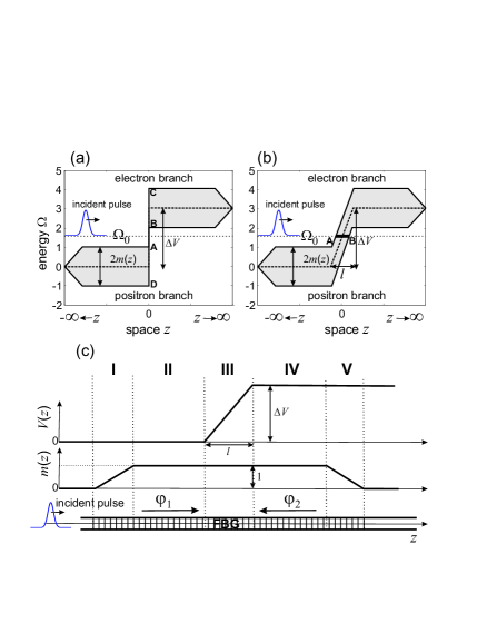
To realize the analogue of KT, let us first assume that the optical pulse propagates in a region of the grating where is uniform and equal to one, and let us assume a chirp profile that mimics a step potential with an increase from to which occurs over a length (see Fig.1). Since for the Dirac equation (3) written in dimensionless units the Compton length is and the rest energy is , according to Sauter’s analysis KT is expected to be observable for smaller than and for a potential height larger than Sauter ; Calogeracos99 ; Emilio . The process of KT and tunneling inhibition for a smooth potential step can be simply explained by a graphical analysis of the space-energy diagrams of the one-dimensional Dirac equation Calogeracos99 , which are shown in Figs.1(a) and (b) for a sharp and for a smooth potential step, respectively. For the sake of clearness, in the figures the potential has been chosen to yield a nonvanishing and constant chirp rate over a length ; different forms for the potential step, such as the profile considered in the seminal work by Sauter Sauter , can be assumed as well without changing the main results.
The space-energy diagrams of Figs.1(a) and (b) schematically show
the behavior of the energy spectrum of Eq.(3) versus , which is
composed by two branches -the electron and positron energy branches
of the Dirac equation- separated by a gap of width and
centered along the curve . The gap regions are
visualized in the diagrams by the shaded areas. A wave packet
(optical pulse) in the electron branch with an initial mean energy
() coming from tunnels into the region after crossing a forbidden
energy region, indicated by the bold segment AB in Fig.1(b), which
vanishes for a sharp potential step [, see Fig.1(a)]. According
to Sauter’s analysis Sauter ; Calogeracos99 , the tunneling
probability is appreciable provided that is smaller than . In the FBG context, the energy diagrams of Fig.1 are equivalent
to the band-reflection diagrams introduced by Poladian for a
graphical analysis of nonuniform gratings Poladian , where the
energy represents the frequency detuning of the incoming
wave from the Bragg frequency . The Sauter’s condition for KT can be derived following the analysis of
Ref.Poladian by computation of the transmittance of the
effective grating associated to the evanescent region AB shown in
Fig.1(b) (see Sec.V.A of Ref.Poladian ). In the previous
discussion, we assumed , however for a grating with finite
spatial extent one has as . To inject and to eject the optical pulse into the
grating region around , an input and an output apodization
sections can be introduced, which adiabatically convert the input
and output wave packets from the regions into the
grating region (see Fig.1). Therefore, the general structure of the
FBG that realizes a photonic analogue of relativistic tunneling
across a potential step consists of five sections, as shown in
Fig.1(c): two boundary apodization sections (regions I and V), and
two uniform sections (regions II and IV) separated by a central
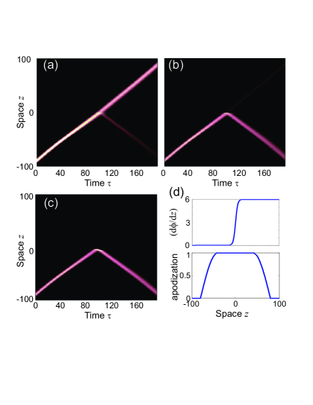
chirped section of length (region III). In Figs. 2(a-c)
typical examples of pulse tunneling across the potential step
are presented, showing KT
for a sharp potential step [Fig.2(a)] and inhibition of tunneling as
the step gets smooth [Fig.2(b) and (c)]. The figures depict the
temporal evolution of
-which is
proportional to the field intensity averaged in time over a few
optical cycles and in space over a few wavelengths- as obtained by
numerical analysis of Eqs.(1) and (2) for a grating length of
with a quarter-cosine apodization profile [see Fig.2(d)],
, and for a few values of . A forward-propagating
Gaussian pulse of mean energy coming from
and of duration (FWHM in intensity)
has been assumed as an initial condition. For typical
parameter values , and
nm, which apply to FBGs used
in optical communications, the spatial and temporal scales in Fig.2
are mm and ps, respectively. Hence, in
physical units the grating length is cm, whereas the
optical analogue of the Compton length is
mm. Such nonuniform FBG structures should be realizable with current
FBG technology based on UV continuous laser writing fab . It
should be finally noticed that, as in an experiment the tracing of
pulse evolution in the grating (Fig.2) can be a nontrivial task, the
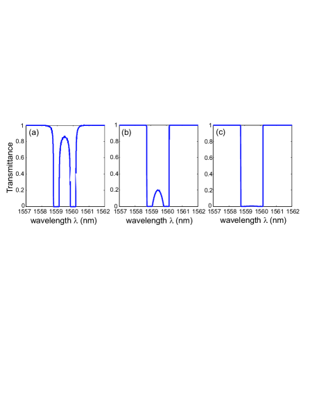
signatures of KT can be simply obtained from standard spectral
transmission measurements of the grating. In fact, for a given value
of and according to the band diagram of Fig.1(a), in
the KT regime a transmission window at [the
segment AB in Fig.1(a)], embedded into the two gaps and [the segments BC and AD in
Fig.1(a)] should be observed in the transmission spectrum, the
suppression of KT for a smooth potential corresponding to the
lowering of such a transmission window. This is clearly shown in
Fig.3, where the spectral transmittance of the FBGs corresponding to
the simulations of Figs.2(a), (b) and (c) are depicted. Note that,
as the length of the chirped region is increased [from Fig.3(a)
to 3(c)], the transmission window embedded in the two adjacent gaps
disappears, which is the signature of KT inhibition.
IV Conclusions
In conclusion, a photonic analogue of Klein tunneling based on pulse propagation in nonuniform fiber Bragg gratings has been proposed. As compared to other photonic analogues of KT recently proposed in Refs. Segevun ; Longhi10 and based on spatial light propagation in periodic photonic structures, the phenomenon of KT in FBGs suggested in this work can be simply observed in the frequency domain as the opening of a transmission window inside the grating stop band, provided that the impressed chirp is realized over a length of the order of the analogue of the Compton wavelength. Such a FBG-based system might be thus considered to be the simplest optical analogue proposed so far to observe KT.
V Acknowledgements
The author acknowledges financial support by the Italian MIUR (Grant No. PRIN-2008-YCAAK project ”Analogie ottico-quantistiche in strutture fotoniche a guida d’onda”).
References
- (1) O. Klein, ”Die reflexion von elektronen an einem potentialsprung nach der relativistischen dynamik von Dirac”, Z. Phys. 53, 157 (1929).
- (2) A. Calogeracos and N. Dombey, ”History and physics of the Klein paradox”, Contemp. Phys. 40, 313 (1999).
- (3) F. Sauter, ”Uber das Verhalten eines Elektrons im homogenen elektrischen Feld nach der relativistischen Theorie Diracs”, Z. Phys. 69, 742 (1931).
- (4) P. Christillin and E. d’Emilio, ”Role of the slope of realistic potential barriers in preventing relativistic tunneling in the Klein zone”, Phys. Rev. A 76, 042104 (2007).
- (5) A. Calogeracos, ”Paradox in a pencil”, Nature Phys. 2, 579 (2006).
- (6) M.I. Katsnelson, K.S. Novoselov, and A.K. Geim, ”Chiral tunnelling and the Klein paradox in graphene”, Nature Phys. 2, 620 (2006).
- (7) A.F. Young and P. Kim, ”Quantum interference and Klein tunnelling in graphene heterojunctions”, Nature Phys. 5, 222 (2009).
- (8) N. Stander, B. Huard, and D. Goldhaber-Gordon, ”Evidence for Klein Tunneling in Graphene p-n Junctions”, Phys. Rev. Lett. 102, 026807 (2009).
- (9) S. Longhi, ”Quantum-optical analogies using photonic structures”, Laser & Photon. Rev. 3, 243 (2009).
- (10) O. Bahat-Treidel, O. Peleg, M. Grobman, N- Shapira, T. Pereg-Barnea, and M. Segev, ”Perfect Klein tunneling in anisotropic graphene-like photonic lattices”, Phys. Rev. Lett. 104, 063901 (2010).
- (11) R.A. Sepkhanov, Ya. B. Bazaliy, and C.W.J. Beenakker, ”Extremal transmission at the Dirac point of a photonic band structure”, Phys. Rev. A 75, 063813 (2007).
- (12) O. Peleg, G. Bartal, B. Freedman, O. Manela, M. Segev, and D.N. Christodoulides, ”Conical Diffraction and Gap Solitons in Honeycomb Photonic Lattices”, Phys. Rev. Lett. 98, 103901 (2007).
- (13) D Ö. Güney and D.A. Meyer, ”Negative refraction gives rise to the Klein paradox”, Phys. Rev. A 79, 063834 (2009).
- (14) S. Longhi, ”Klein tunneling in binary photonic superlattices”, Phys. Rev. B 81, 075102 (2010).
- (15) J. Otterbach, R.G. Unanyan, and M. Fleischhauer, ”Confining Stationary Light: Dirac Dynamics and Klein Tunneling”, Phys. Rev. Lett. 102, 063602 (2009).
- (16) A. M. Steinberg, P. G. Kwiat, and R. Y. Chiao, ”Measurement of the single-photon tunneling time”, Phys. Rev. Lett. 71, 708 (1993).
- (17) S. Longhi, P. Laporta, M. Belmonte, and E. Recami, ”Measurement of superluminal optical tunneling times in double-barrier photonic band gaps”, Phys. Rev. E 65, 046610 (2002).
- (18) S. Longhi, M. Marano, M. Belmonte, and P. Laporta, ”Superluminal Pulse Propagation in Linear and Nonlinear Photonic Grating Structures”, IEEE J. Sel. Topics Quant. Electron. 9, 4 (2003).
- (19) J.E. Sipe, L. Poladian, and C.M. de Sterke, ”Propagation through nonuniform grating structures”, J. Opt. Soc. Am. B 11, 1307 (1994).
- (20) L. Poladian, ”Graphical and WKB analysis of nonuniform Bragg gratings”, Phys. Rev. E 48, 4758 (1993).
- (21) A. Asseh, H. Storoy, B. Sahlgren, and R. Stubbe, ”A writing technique for long fiber Bragg gratings with complex reflectivity profiles”, J. Lightwave Technol. 15, 1419 (1997).